I picked up a horsehair dust brush from eBay as a lightweight substitute for the Electrolux aluminum ball, discovered that an adapter I’d already made fit perfectly, did the happy dance, and printed one for the brush. That worked perfectly for half a year, whereupon:

It broke about where I expected, along the layer lines at the cross section where the snout joins the fitting. You can see the three perimeter shells I hoped would strengthen the part:
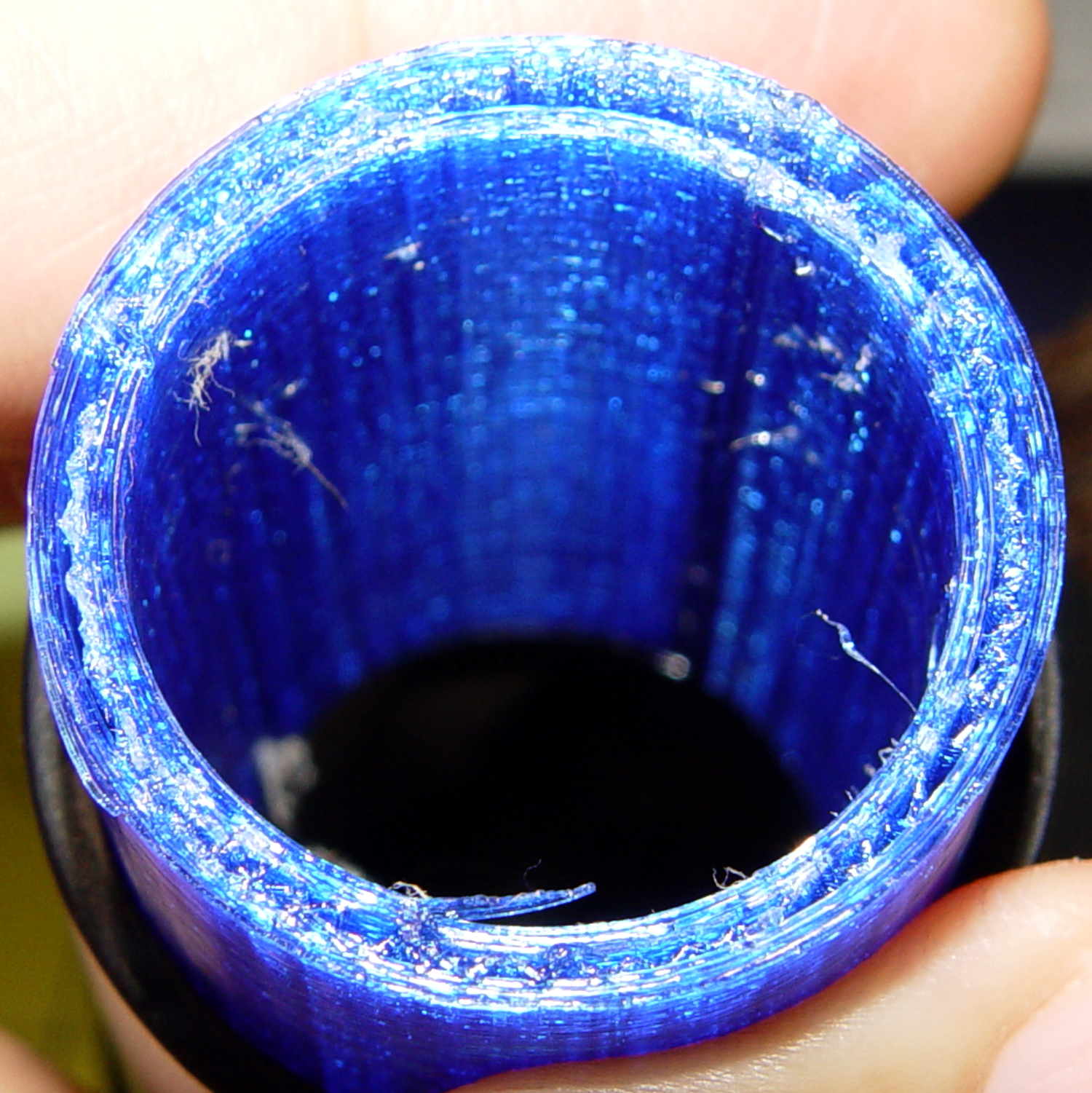
That has the usual 15% 3D Honeycomb infill, although there’s not a lot area for infill.
There’s obviously a stress concentration there and making the wall somewhat thicker (to get more plastic-to-plastic area) might suffice. I’m not convinced the layer bonding would be good enough, even with more wall area, to resist the stress; that’s pretty much a textbook example of how & where 3D printed parts fail.
That cross section should look like this:

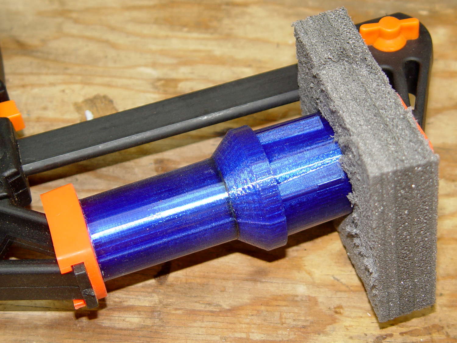
Anyhow, I buttered the snout’s broken end with JB Kwik epoxy, aligned the parts, and clamped them overnight:
The source code now has a separate solid model for the dust brush featuring a slightly shorter snout; if when the epoxy fails, we’ll see how that changes the results. I could add ribs and suchlike along the outside, none of which seem worth the effort right now. Fairing the joint between those two straight sections would achieve the same end, with even more effort, because OpenSCAD.
The OpenSCAD source code as a GitHub Gist:
| // Kenmore vacuum cleaner nozzle adapters | |
| // Ed Nisley KE4ZNU August 2016 | |
| // Layout options | |
| Layout = "DustBrush"; // MaleFitting CoilWand FloorBrush CreviceTool ScrubbyTool LuxBrush DustBrush | |
| //- Extrusion parameters must match reality! | |
| // Print with +1 shells and 3 solid layers | |
| ThreadThick = 0.25; | |
| ThreadWidth = 0.40; | |
| HoleWindage = 0.2; | |
| function IntegerMultiple(Size,Unit) = Unit * ceil(Size / Unit); | |
| Protrusion = 0.1; // make holes end cleanly | |
| //———————- | |
| // Dimensions | |
| ID1 = 0; // for tapered tubes | |
| ID2 = 1; | |
| OD1 = 2; | |
| OD2 = 3; | |
| LENGTH = 4; | |
| OEMTube = [35.0,35.0,41.7,40.5,30.0]; // main fitting tube | |
| EndStop = [OEMTube[ID1],OEMTube[ID2],47.5,47.5,6.5]; // flange at end of main tube | |
| FittingOAL = OEMTube[LENGTH] + EndStop[LENGTH]; | |
| $fn = 12*4; | |
| //———————- | |
| // Useful routines | |
| module PolyCyl(Dia,Height,ForceSides=0) { // based on nophead's polyholes | |
| Sides = (ForceSides != 0) ? ForceSides : (ceil(Dia) + 2); | |
| FixDia = Dia / cos(180/Sides); | |
| cylinder(r=(FixDia + HoleWindage)/2,h=Height,$fn=Sides); | |
| } | |
| //——————- | |
| // Male fitting on end of Kenmore tools | |
| // This slides into the end of the handle or wand and latches firmly in place | |
| module MaleFitting() { | |
| Latch = [40,11.5,5.0]; // rectangle latch opening | |
| EntryAngle = 45; // latch entry ramp | |
| EntrySides = 16; | |
| EntryHeight = 15.0; // lower edge on *inside* of fitting | |
| KeyRadius = 1.0; | |
| translate([0,0,6.5]) | |
| difference() { | |
| union() { | |
| cylinder(d1=OEMTube[OD1],d2=OEMTube[OD2],h=OEMTube[LENGTH]); // main tube | |
| hull() // insertion guide | |
| for (i=[-(6.0/2 – KeyRadius),(6.0/2 – KeyRadius)], | |
| j=[-(28.0/2 – KeyRadius),(28.0/2 – KeyRadius)], | |
| k=[-(26.0/2 – KeyRadius),(26.0/2 – KeyRadius)]) | |
| translate([(i – (OEMTube[ID1]/2 + OEMTube[OD1]/2)/2 + 6.0/2),j,(k + 26.0/2 – 1.0)]) | |
| sphere(r=KeyRadius,$fn=8); | |
| translate([0,0,-EndStop[LENGTH]]) // wand tube butts against this | |
| cylinder(d=EndStop[OD1],h=EndStop[LENGTH] + Protrusion); | |
| } | |
| translate([0,0,-OEMTube[LENGTH]]) // main bore | |
| cylinder(d=OEMTube[ID1],h=2*OEMTube[LENGTH] + 2*Protrusion); | |
| translate([0,-11.5/2,23.0 – 5.0]) // latch opening | |
| cube(Latch); | |
| translate([OEMTube[ID1]/2 + EntryHeight/tan(90-EntryAngle),0,0]) // latch ramp | |
| translate([(Latch[1]/cos(180/EntrySides))*cos(EntryAngle)/2,0,(Latch[1]/cos(180/EntrySides))*sin(EntryAngle)/2]) | |
| rotate([0,-EntryAngle,0]) | |
| intersection() { | |
| rotate(180/EntrySides) | |
| PolyCyl(Latch[1],Latch[0],EntrySides); | |
| translate([-(2*Latch[0])/2,0,-Protrusion]) | |
| cube(2*Latch[0],center=true); | |
| } | |
| } | |
| } | |
| //——————- | |
| // Refrigerator evaporator coil wand | |
| module CoilWand() { | |
| union() { | |
| translate([0,0,50.0]) | |
| rotate([180,0,0]) | |
| difference() { | |
| cylinder(d1=EndStop[OD1],d2=42.0,h=50.0); | |
| translate([0,0,-Protrusion]) | |
| cylinder(d1=35.0,d2=35.8,h=100); | |
| } | |
| translate([0,0,50.0 – Protrusion]) | |
| MaleFitting(); | |
| } | |
| } | |
| //——————- | |
| // Samsung floor brush | |
| module FloorBrush() { | |
| union() { | |
| translate([0,0,60.0]) | |
| rotate([180,0,0]) | |
| difference() { | |
| union() { | |
| cylinder(d1=EndStop[OD1],d2=32.4,h=10.0); | |
| translate([0,0,10.0 – Protrusion]) | |
| cylinder(d1=32.4,d2=30.7,h=50.0 + Protrusion); | |
| } | |
| translate([0,0,-Protrusion]) | |
| cylinder(d1=28.0,d2=24.0,h=100); | |
| } | |
| translate([0,0,60.0 – Protrusion]) | |
| MaleFitting(); | |
| } | |
| } | |
| //——————- | |
| // Crevice tool | |
| module CreviceTool() { | |
| union() { | |
| translate([0,0,60.0]) | |
| rotate([180,0,0]) | |
| difference() { | |
| union() { | |
| cylinder(d1=EndStop[OD1],d2=32.0,h=10.0); | |
| translate([0,0,10.0 – Protrusion]) | |
| cylinder(d1=32.0,d2=30.4,h=50.0 + Protrusion); | |
| } | |
| translate([0,0,-Protrusion]) | |
| cylinder(d1=28.0,d2=24.0,h=100); | |
| } | |
| translate([0,0,60.0 – Protrusion]) | |
| MaleFitting(); | |
| } | |
| } | |
| //——————- | |
| // Mystery brush | |
| module ScrubbyTool() { | |
| union() { | |
| translate([0,0,60.0]) | |
| rotate([180,0,0]) | |
| difference() { | |
| union() { | |
| cylinder(d1=EndStop[OD1],d2=31.8,h=10.0); | |
| translate([0,0,10.0 – Protrusion]) | |
| cylinder(d1=31.8,d2=31.0,h=50.0 + Protrusion); | |
| } | |
| translate([0,0,-Protrusion]) | |
| cylinder(d1=26.0,d2=24.0,h=100); | |
| } | |
| translate([0,0,60.0 – Protrusion]) | |
| MaleFitting(); | |
| } | |
| } | |
| //——————- | |
| // eBay horsehair dusting brush | |
| module DustBrush() { | |
| union() { | |
| translate([0,0,40.0]) | |
| rotate([180,0,0]) | |
| difference() { | |
| union() { | |
| cylinder(d1=EndStop[OD1],d2=31.8,h=10.0); | |
| translate([0,0,10.0 – Protrusion]) | |
| cylinder(d1=31.6,d2=31.8,h=30.0 + Protrusion); | |
| } | |
| translate([0,0,-Protrusion]) | |
| cylinder(d1=26.0,d2=24.0,h=100); | |
| } | |
| translate([0,0,40.0 – Protrusion]) | |
| MaleFitting(); | |
| } | |
| } | |
| //——————- | |
| // Electrolux brush ball | |
| module LuxBrush() { | |
| union() { | |
| translate([0,0,30.0]) | |
| rotate([180,0,0]) | |
| difference() { | |
| union() { | |
| cylinder(d1=EndStop[OD1],d2=30.8,h=10.0); | |
| translate([0,0,10.0 – Protrusion]) | |
| cylinder(d1=30.8,d2=30.0,h=20.0 + Protrusion); | |
| } | |
| translate([0,0,-Protrusion]) | |
| cylinder(d1=25.0,d2=23.0,h=30 + 2*Protrusion); | |
| } | |
| translate([0,0,30.0 – Protrusion]) | |
| MaleFitting(); | |
| } | |
| } | |
| //———————- | |
| // Build it! | |
| if (Layout == "MaleFitting") | |
| MaleFitting(); | |
| if (Layout == "CoilWand") | |
| CoilWand(); | |
| if (Layout == "FloorBrush") | |
| FloorBrush(); | |
| if (Layout == "CreviceTool") | |
| CreviceTool(); | |
| if (Layout == "DustBrush") | |
| DustBrush(); | |
| if (Layout == "ScrubbyTool") | |
| ScrubbyTool(); | |
| if (Layout == "LuxBrush") | |
| LuxBrush(); |

Comments
9 responses to “Kenmore Progressive Vacuum Tool Adapters: First Failure”
I doubt epoxy will fail, especially when you have so ragged glue line with lot of nooks and crannies which provide a good mechanical grip. Next crack will more than likely be adjacent to your repair.
If you’re open to printing it in ABS, you could treat it with acetone afterwards for better layer bonding, plus when it fails no need to break out epoxy – acetone will suffice :)
It definitely needs more meat in that section: I’ll run off a bigger & better one when it breaks exactly as you describe.
My ABS printing days are over: PETG works about as well for my simple needs and doesn’t delaminate / crack / break off the platform at all. It’s a bit more bendy and definitely more stringy, neither of which bother me nearly as much as maybe they should.
Well, I hate printing ABS, even now when I have a heated chamber and can print largish parts with reasonable chance of success.
But PETG I tried (colorfabb XT which should be awesome) really wasn’t much better. It still lifted, prints were neither resilient nor hard, and the price was definitely not right in my corner of the world. Still trying out nylon but it doesn’t look good so far :)
I think of 3D printed parts similarly to how I think of wood parts in the sense that they have more strength in some axes than others, but with 3D printing I can control the “grain” alignment to some extent. In this case however, to have the grain aligned optimally, you’d have to print it sideways, which pretty much means printing it in two halves, which would require support structure and another assembly step. At some point, I realize that 3D printing isn’t optimal for permanent solutions to some problems.
Aye! The only sensible way to print those adapters is standing on end, then hope for enough strength that they’ll survive. Not wanting to screw around with support & assembly had a lot to do with that!
In truth, they’re entirely “good enough” for our needs, even if they’d collect one-star reviews in a commercial channel: I can always bang out another one, just like the other one, as needed.
That would work if part was only in compression radially, but i don’t think that’s the case. If you jam a pipe in one end, it’s just gonna snap open.
Ed, you could try printing it a bit hotter next time, you might get a little better interlayer bonding.
Instead of taking a union of two “cylinders” for the lower portion, why not draw it as a profile and rotate extrude it? Then you can more easily adjust the shape to add things like “fairing the joint”.
That makes a lot more sense!
After figuring the first adapter by using nested cylinders, the rest required little more than tweaking the parameters. Now that I know what’s needed, I should go back and redesign ’em right.
Thanks for the nudge…
[…] Pretty much as expected, the dust brush nozzle failed again, adjacent to the epoxy repair: […]