The Smell of Molten Projects in the Morning

Ed Nisley's Blog: Shop notes, electronics, firmware, machinery, 3D printing, laser cuttery, and curiosities. Contents: 100% human thinking, 0% AI slop.

Tag: M2

Using and tweaking a Makergear M2 3D printer

  • SK2812 RGBW LED: Test Fixture

    [Edit: The SK2812 in the title and elsewhere should be SK6812. If I change the title, then all the other links break. So it goes.]

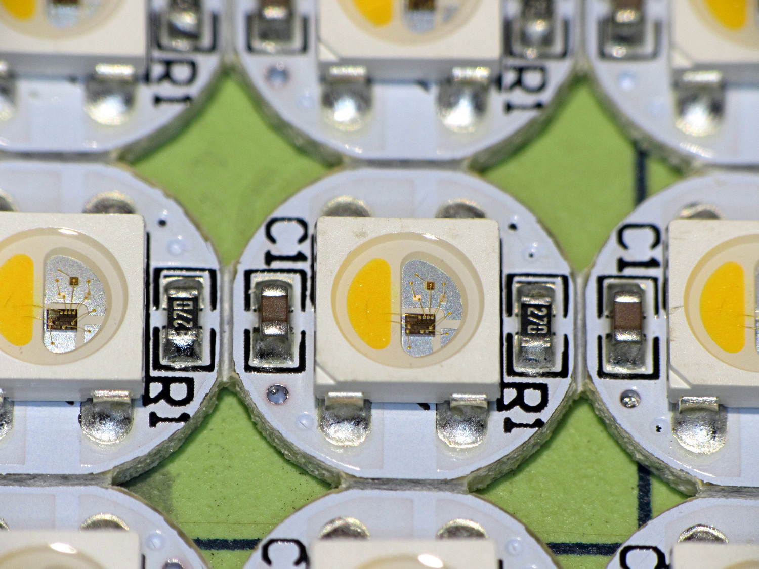
    An envelope of RGBW LEDs, allegedly with SK6812 controllers, arrived from halfway around the planet:
    SK2812RGBW LEDs - as received
    SK2812RGBW LEDs – as received

    The yellow phosphor sauce poured atop the blue LED on the left that makes it glow white leaves the upper loop of two wire bonds sticking out, but I can’t fault ’em for that. The overall build quality looks better than the ill-fated WS2812 LEDs, although it’s hard to tell by looking.

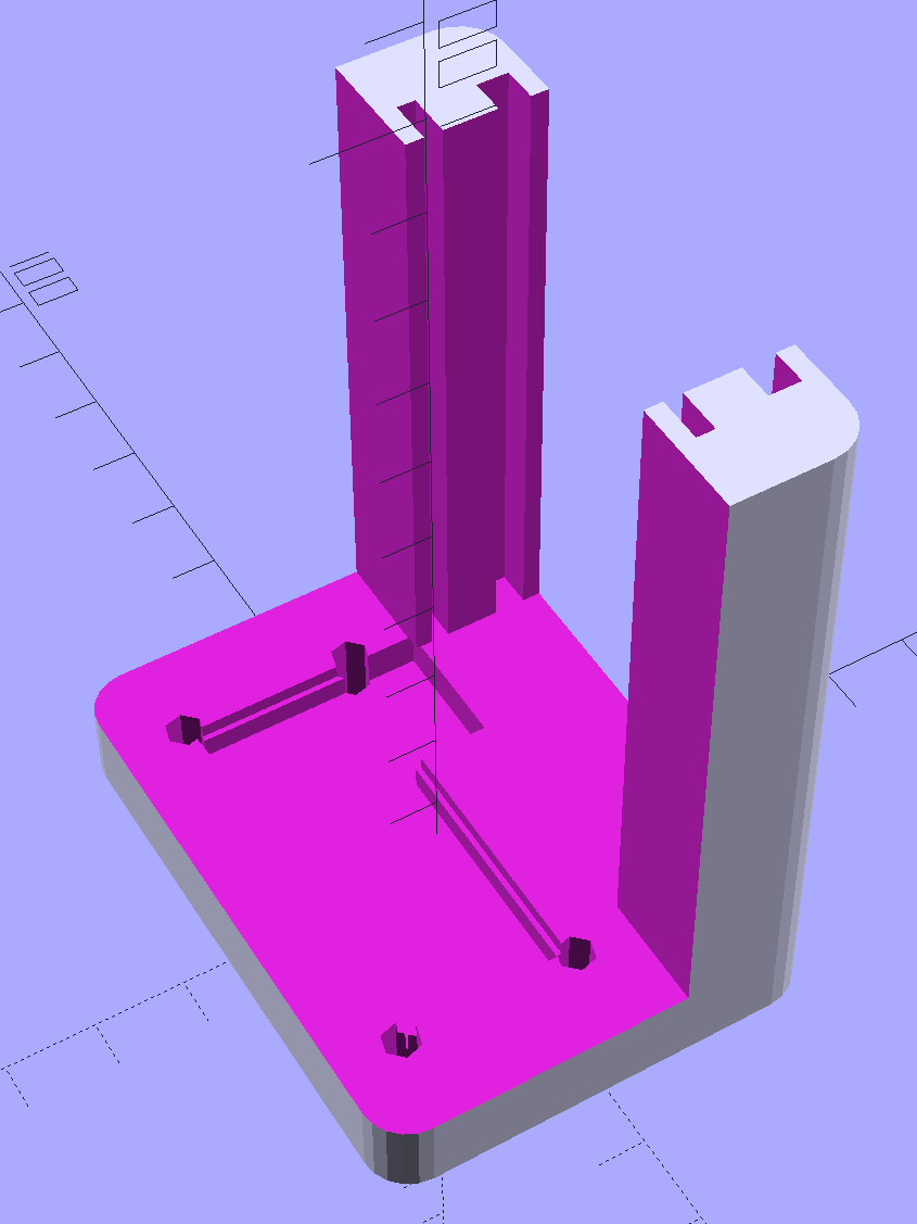
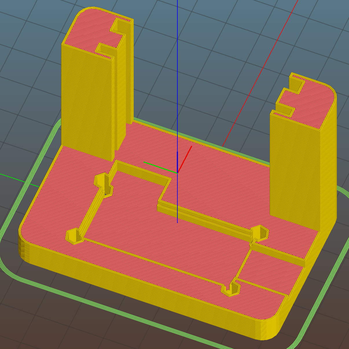
    I conjured a test stand from the vasty digital deep by tweaking the WS2812 mount:
    SK6812 LED Array Test Fixture - Slic3r preview
    SK6812 LED Array Test Fixture – Slic3r preview

    Wiring up a 5×5 panel went as before:

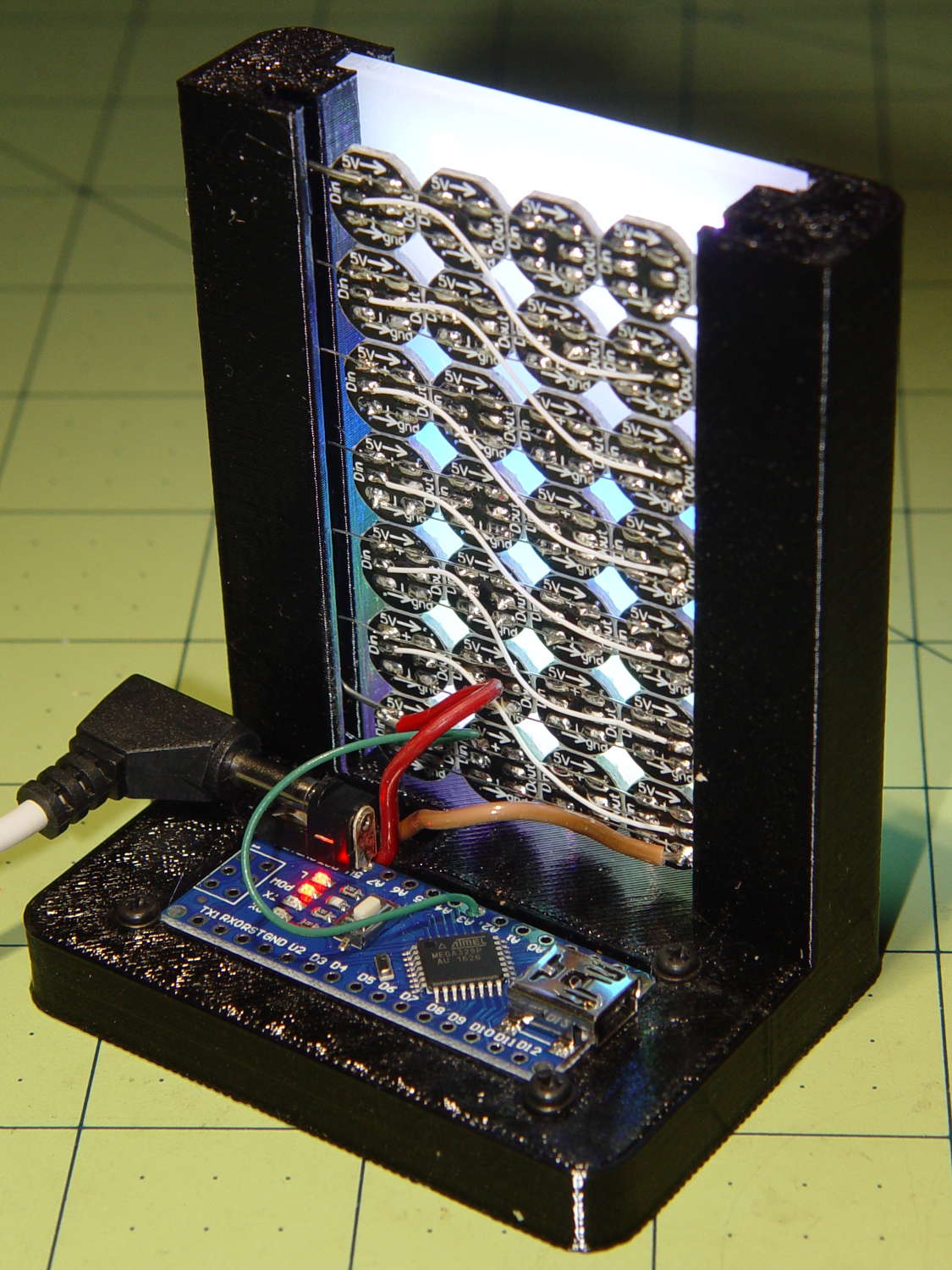
    SK2812RGBW test fixture - rear
    SK2812RGBW test fixture – rear

    The array test code adds another pixel channel and runs another raised sine wave with another random period, accomplished without much hackage.

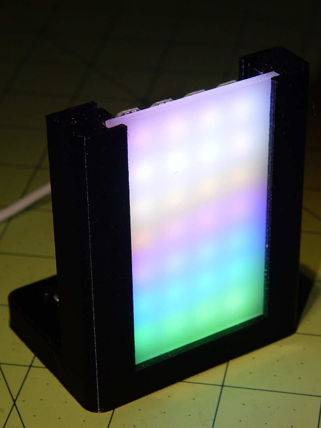
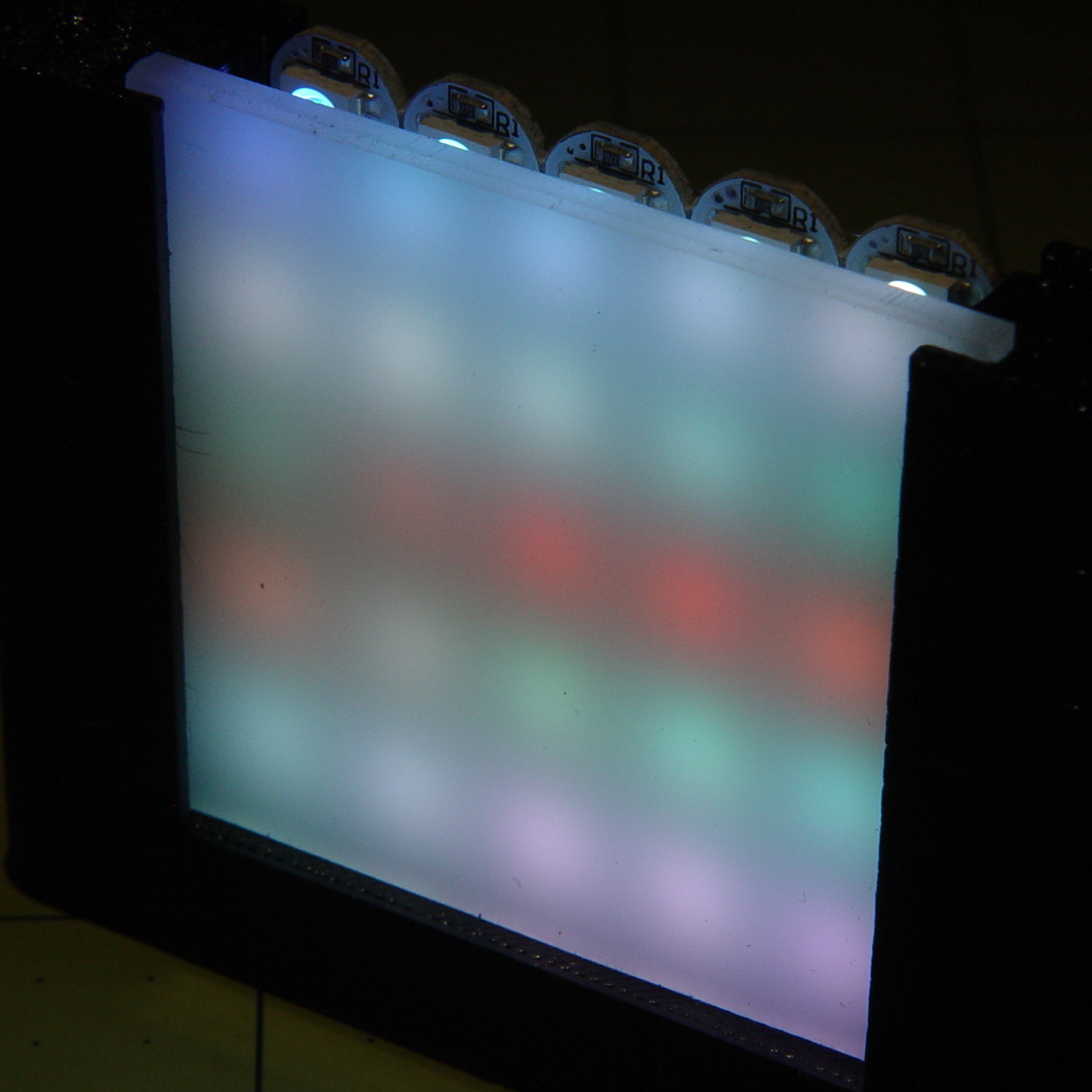
    With the warm-white LED at full throttle (MaxPWM = 255), the panel tends toward the pallid end of HSV space:
    SK2812RGBW test fixture - front - W PWM255
    SK2812RGBW test fixture – front – W PWM255

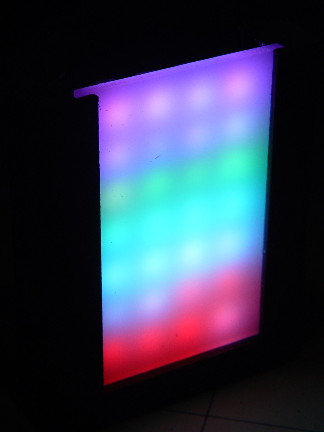
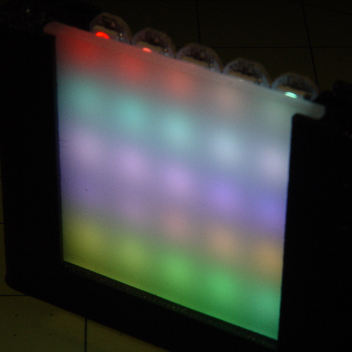
    Dialing the white MaxPWM back to 32 crisps things a bit:
    SK2812RGBW test fixture - front - W PWM32
    SK2812RGBW test fixture – front – W PWM32

    Of course, the RGBW data stream isn’t compatible with the RGB data stream, so vacuum tubes with SK6812 chips require a slightly different driver and I can’t mix the two chips on a single tube.

    The Arduino source code as a GitHub Gist:

    // SK6812 RGBW LED array exerciser
    // Ed Nisley – KE4ANU – February 2017
    #include <Adafruit_NeoPixel.h>
    //———-
    // Pin assignments
    const byte PIN_NEO = A3; // DO – data out to first Neopixel
    const byte PIN_HEARTBEAT = 13; // DO – Arduino LED
    //———-
    // Constants
    #define UPDATEINTERVAL 20ul
    const unsigned long UpdateMS = UPDATEINTERVAL – 1ul; // update LEDs only this many ms apart minus loop() overhead
    // number of steps per cycle, before applying prime factors
    #define RESOLUTION 100
    // phase difference between LEDs for slowest color
    #define BASEPHASE (PI/16.0)
    // LEDs in each row
    #define NUMCOLS 5
    // number of rows
    #define NUMROWS 5
    #define NUMPIXELS (NUMCOLS * NUMROWS)
    #define PINDEX(row,col) (row*NUMCOLS + col)
    //———-
    // Globals
    // instantiate the Neopixel buffer array
    Adafruit_NeoPixel strip = Adafruit_NeoPixel(NUMPIXELS, PIN_NEO, NEO_GRBW + NEO_KHZ800);
    uint32_t FullWhite = strip.Color(255,255,255,255);
    uint32_t FullOff = strip.Color(0,0,0,0);
    struct pixcolor_t {
    byte Prime;
    unsigned int NumSteps;
    unsigned int Step;
    float StepSize;
    float TubePhase;
    byte MaxPWM;
    };
    // colors in each LED
    enum pixcolors {RED, GREEN, BLUE, WHITE, PIXELSIZE};
    struct pixcolor_t Pixels[PIXELSIZE]; // all the data for each pixel color intensity
    unsigned long MillisNow;
    unsigned long MillisThen;
    //– Figure PWM based on current state
    byte StepColor(byte Color, float Phi) {
    byte Value;
    Value = (Pixels[Color].MaxPWM / 2.0) * (1.0 + sin(Pixels[Color].Step * Pixels[Color].StepSize + Phi));
    // Value = (Value) ? Value : Pixels[Color].MaxPWM; // flash at dimmest points
    // printf("C: %d Phi: %d Value: %d\r\n",Color,(int)(Phi*180.0/PI),Value);
    return Value;
    }
    //– Helper routine for printf()
    int s_putc(char c, FILE *t) {
    Serial.write(c);
    }
    //——————
    // Set the mood
    void setup() {
    pinMode(PIN_HEARTBEAT,OUTPUT);
    digitalWrite(PIN_HEARTBEAT,LOW); // show we arrived
    Serial.begin(57600);
    fdevopen(&s_putc,0); // set up serial output for printf()
    printf("WS2812 / SK6812 array exerciser\r\nEd Nisley – KE4ZNU – February 2017\r\n");
    /// set up Neopixels
    strip.begin();
    strip.show();
    // lamp test: run a brilliant white dot along the length of the strip
    printf("Lamp test: walking white\r\n");
    strip.setPixelColor(0,FullWhite);
    strip.show();
    delay(250);
    for (int i=1; i<NUMPIXELS; i++) {
    digitalWrite(PIN_HEARTBEAT,HIGH);
    strip.setPixelColor(i-1,FullOff);
    strip.setPixelColor(i,FullWhite);
    strip.show();
    digitalWrite(PIN_HEARTBEAT,LOW);
    delay(250);
    }
    strip.setPixelColor(NUMPIXELS – 1,FullOff);
    strip.show();
    delay(250);
    // fill the array, row by row
    printf(" … fill\r\n");
    for (int i=NUMROWS-1; i>=0; i–) { // for each row
    digitalWrite(PIN_HEARTBEAT,HIGH);
    for (int j=NUMCOLS-1; j>=0 ; j–) {
    strip.setPixelColor(PINDEX(i,j),FullWhite);
    strip.show();
    delay(100);
    }
    digitalWrite(PIN_HEARTBEAT,LOW);
    }
    // clear to black, column by column
    printf(" … clear\r\n");
    for (int j=NUMCOLS-1; j>=0; j–) { // for each column
    digitalWrite(PIN_HEARTBEAT,HIGH);
    for (int i=NUMROWS-1; i>=0; i–) {
    strip.setPixelColor(PINDEX(i,j),FullOff);
    strip.show();
    delay(100);
    }
    digitalWrite(PIN_HEARTBEAT,LOW);
    }
    delay(1000);
    // set up the color generators
    MillisNow = MillisThen = millis();
    printf("First random number: %ld\r\n",random(10));
    Pixels[RED].Prime = 3;
    Pixels[GREEN].Prime = 5;
    Pixels[BLUE].Prime = 7;
    Pixels[WHITE].Prime = 11;
    printf("Primes: (%d,%d,%d,%d)\r\n",
    Pixels[RED].Prime,Pixels[GREEN].Prime,Pixels[BLUE].Prime,Pixels[WHITE].Prime);
    unsigned int PixelSteps = (unsigned int) ((BASEPHASE / TWO_PI) *
    RESOLUTION * (unsigned int) max(max(max(Pixels[RED].Prime,Pixels[GREEN].Prime),Pixels[BLUE].Prime),Pixels[WHITE].Prime));
    printf("Pixel phase offset: %d deg = %d steps\r\n",(int)(BASEPHASE*(360.0/TWO_PI)),PixelSteps);
    Pixels[RED].MaxPWM = 255;
    Pixels[GREEN].MaxPWM = 255;
    Pixels[BLUE].MaxPWM = 255;
    Pixels[WHITE].MaxPWM = 32;
    for (byte c=0; c < PIXELSIZE; c++) {
    Pixels[c].NumSteps = RESOLUTION * (unsigned int) Pixels[c].Prime;
    Pixels[c].Step = (3*Pixels[c].NumSteps)/4;
    Pixels[c].StepSize = TWO_PI / Pixels[c].NumSteps; // in radians per step
    Pixels[c].TubePhase = PixelSteps * Pixels[c].StepSize; // radians per tube
    printf("c: %d Steps: %5d Init: %5d",c,Pixels[c].NumSteps,Pixels[c].Step);
    printf(" PWM: %3d Phi %3d deg\r\n",Pixels[c].MaxPWM,(int)(Pixels[c].TubePhase*(360.0/TWO_PI)));
    }
    }
    //——————
    // Run the mood
    void loop() {
    MillisNow = millis();
    if ((MillisNow – MillisThen) > UpdateMS) {
    digitalWrite(PIN_HEARTBEAT,HIGH);
    unsigned int AllSteps = 0;
    for (byte c=0; c < PIXELSIZE; c++) { // step to next increment in each color
    if (++Pixels[c].Step >= Pixels[c].NumSteps) {
    Pixels[c].Step = 0;
    printf("Color %d steps %5d at %8ld delta %ld ms\r\n",c,Pixels[c].NumSteps,MillisNow,(MillisNow – MillisThen));
    }
    AllSteps += Pixels[c].Step; // will be zero only when all wrap at once
    }
    if (0 == AllSteps) {
    printf("Grand cycle at: %ld\r\n",MillisNow);
    }
    for (int k=0; k < NUMPIXELS; k++) { // for each pixel
    byte Value[PIXELSIZE];
    for (byte c=0; c < PIXELSIZE; c++) { // … for each color
    Value[c] = StepColor(c,-k*Pixels[c].TubePhase); // figure new PWM value
    // Value[c] = (c == RED && Value[c] == 0) ? Pixels[c].MaxPWM : Value[c]; // flash highlight for tracking
    }
    uint32_t UniColor = strip.Color(Value[RED],Value[GREEN],Value[BLUE],Value[WHITE]);
    strip.setPixelColor(k,UniColor);
    }
    strip.show();
    MillisThen = MillisNow;
    digitalWrite(PIN_HEARTBEAT,LOW);
    }
    }

  • ShopVac Hose Barb Adapter

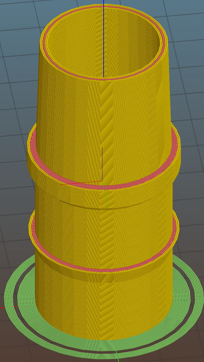
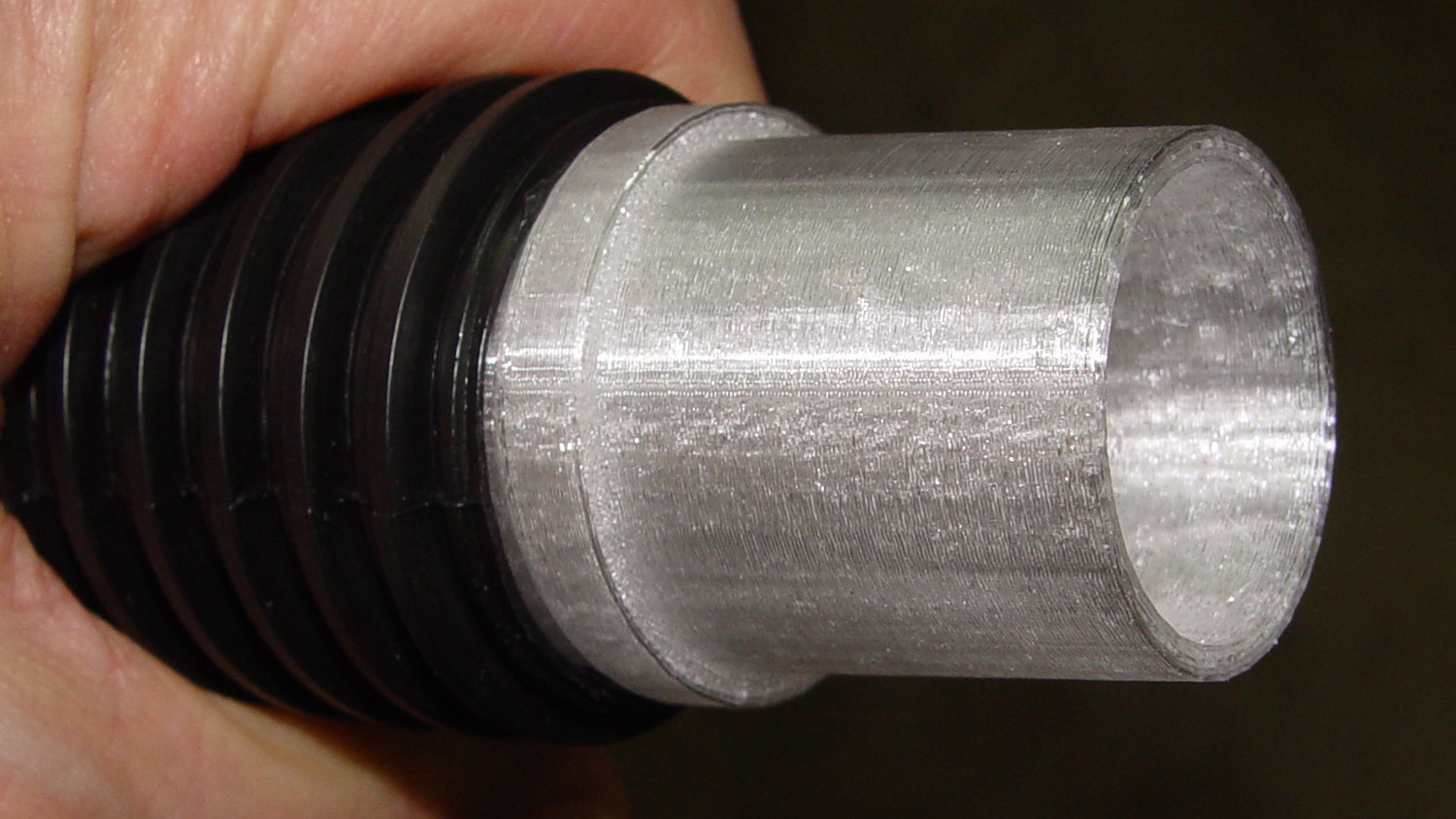
    A small ShopVac arrived with a ribbed hose carrying an absurdly long wand, so I conjured a barbed adapter with a much shorter tapered snout for the machine tools:

    Vacuum hose fittings - hose barb to nozzle
    Vacuum hose fittings – hose barb to nozzle

    Trimming the hose end at one of the ribs makes a tidy fit:

    Vacuum hose fittings - ribbed hose barb
    Vacuum hose fittings – ribbed hose barb

    Now I need not trip over the vacuum hose between the bandsaw bench and the sander bench…

    The OpenSCAD code as a GitHub Gist:

    // Vacuum Hose Fittings
    // Ed Nisley KE4ZNU July 2016
    // March 2017
    Layout = "HoseBarb"; // PVCtoHose ExpandRing PipeToPort FVacPipe FVacFitting HoseBarb
    //- Extrusion parameters must match reality!
    // Print with 2 shells and 3 solid layers
    ThreadThick = 0.25;
    ThreadWidth = 0.40;
    HoleWindage = 0.2;
    Protrusion = 0.1; // make holes end cleanly
    //———————-
    // Dimensions
    ID = 0;
    OD = 1;
    LENGTH = 2;
    VacNozzle = [30.1,31.8,30.0]; // nozzle on vacuum hose (taper ID to OD over length)
    MINOR = 0;
    MAJOR = 1;
    PITCH = 2;
    FORM_OD = 3;
    HoseThread = [32.0,(37.0 + HoleWindage),4.25,(1.8 + 0.20)]; // vacuum hose thread
    NumSegments = 64; // .. number of cylinder approximations per turn
    $fn = NumSegments;
    ThreadLength = 4 * HoseThread[PITCH];
    ScrewOAL = ThreadLength + HoseThread[PITCH];
    WallThick = 2.5;
    echo(str("Pitch dia: ",HoseThread[MAJOR]));
    echo(str("Root dia: ",HoseThread[MAJOR] – HoseThread[FORM_OD]));
    echo(str("Crest dia: ",HoseThread[MAJOR] + HoseThread[FORM_OD]));
    //———————-
    // Wrap cylindrical thread segments around larger plug cylinder
    module CylinderThread(Pitch,Length,PitchDia,ThreadOD,PerTurn,Chirality = "Left") {
    CylFudge = 1.02; // force overlap
    ThreadSides = 6;
    RotIncr = 1/PerTurn;
    PitchRad = PitchDia/2;
    Turns = Length/Pitch;
    NumCyls = Turns*PerTurn;
    ZStep = Pitch / PerTurn;
    HelixAngle = ((Chirality == "Left") ? -1 : 1) * atan(Pitch/(PI*PitchDia));
    CylLength = CylFudge * (PI*(PitchDia + ThreadOD) / PerTurn) / cos(HelixAngle);
    for (i = [0:NumCyls-1]) {
    Angle = ((Chirality == "Left") ? -1 : 1) * 360*i/PerTurn;
    translate([PitchRad*cos(Angle),PitchRad*sin(Angle),i*ZStep])
    rotate([90+HelixAngle,0,Angle]) rotate(180/ThreadSides)
    cylinder(r1=ThreadOD/2,
    r2=ThreadOD/(2*CylFudge),
    h=CylLength,
    center=true,$fn=ThreadSides);
    }
    }
    //– PVC fitting to vacuum hose
    module PVCtoHose() {
    Fitting = [34.0,41.0,16.0]; // 1 inch PVC elbow
    Adapter = [HoseThread[MAJOR],(Fitting[OD] + 2*WallThick + HoleWindage),(ScrewOAL + Fitting[LENGTH])]; // dimensions for entire fitting
    union() {
    difference() {
    cylinder(d=Adapter[OD],h=Adapter[LENGTH]); // overall fitting
    translate([0,0,-Protrusion]) // remove thread pitch dia
    cylinder(d=HoseThread[MAJOR],h=(ScrewOAL + 2*Protrusion));
    translate([0,0,(ScrewOAL – Protrusion)]) // remove PVC fitting dia
    cylinder(d=(Fitting[OD] + HoleWindage),h=(Fitting[LENGTH] + 2*Protrusion));
    }
    translate([0,0,HoseThread[PITCH]/2]) // add the thread form
    CylinderThread(HoseThread[PITCH],ThreadLength,HoseThread[MAJOR],HoseThread[FORM_OD],NumSegments,"Left");
    }
    }
    //– Expander ring from small OD to large ID PVC fittings
    // So a small elbow on the bandsaw fits into the hose adapter, which may not be long-term useful
    module ExpandRing() {
    Fitting_L = [34.0,41.0,16.0]; // 1 inch PVC pipe elbow
    Fitting_S = [26.8,32.8,17]; // 3/4 inch PVC elbow
    difference() {
    cylinder(d1=Fitting_L[OD],d2=(Fitting_L[OD] – HoleWindage),h=Fitting_L[LENGTH]); // overall fitting
    translate([0,0,-Protrusion])
    cylinder(d=(Fitting_S[OD] + HoleWindage),h=(Fitting_L[LENGTH] + 2*Protrusion));
    }
    }
    //– 1 inch PVC pipe into vacuum port
    // Stick this in the port, then plug a fitting onto the pipe section
    module PipeToPort() {
    Pipe = [26.5,33.5,20.0]; // 1 inch Schedule 40 PVC pipe
    difference() {
    union() {
    cylinder(d=Pipe[OD],h=(Pipe[LENGTH] + Protrusion));
    translate([0,0,(Pipe[LENGTH] – Protrusion)])
    cylinder(d1=VacNozzle[OD],d2=VacNozzle[ID],h=VacNozzle[LENGTH]);
    }
    translate([0,0,-Protrusion])
    cylinder(d=Pipe[ID],h=(Pipe[LENGTH] + VacNozzle[LENGTH] + 2*Protrusion));
    }
    }
    //– Female Vac outlet inside PVC pipe
    // Plug this into PVC fitting, then plug hose + nozzle into outlet
    module FVacPipe() {
    VacPort = [30.0,31.3,25]; // vacuum port on belt sander (taper ID to OD over length)
    Pipe = [26.5,33.5,20.0]; // 1 inch Schedule 40 PVC pipe
    difference() {
    cylinder(d=Pipe[OD],h=VacPort[LENGTH]);
    translate([0,0,-Protrusion])
    cylinder(d1=VacPort[ID],d2=VacPort[OD],h=(VacPort[LENGTH] + 2*Protrusion));
    }
    }
    //– Female Vac outlet on 3/4 inch fitting OD
    // Jam this onto OD of fitting, plug hose + nozzle into outlet
    module FVacFitting() {
    Adapter = [26.5,(33.5 + 2*WallThick),17.0]; // overall adapter
    //VacPort = [30.0,31.3,25]; // vacuum port on belt sander (taper ID to OD over length)
    VacPort = [30.1,31.8,30.0]; // vacuum port for bandsaw = inverse of hose nozzle
    Fitting = [26.8,32.8,17]; // 3/4 inch PVC elbow
    TaperLength = 5.0; // inner taper to avoid overhang
    difference() {
    cylinder(d=Adapter[OD],h=Adapter[LENGTH]); // overall fitting
    translate([0,0,-Protrusion])
    cylinder(d=(Fitting[OD] + HoleWindage),h=(Adapter[LENGTH] + 2*Protrusion));
    }
    translate([0,0,Adapter[LENGTH]])
    difference() {
    cylinder(d=Adapter[OD],h=TaperLength);
    translate([0,0,-Protrusion])
    cylinder(d1=(Fitting[OD] + HoleWindage),d2=VacPort[ID],h=(TaperLength + 2*Protrusion));
    }
    translate([0,0,(TaperLength + Adapter[LENGTH])]) // vac fitting
    difference() {
    cylinder(d=Adapter[OD],h=VacPort[LENGTH]);
    translate([0,0,-Protrusion])
    cylinder(d1=VacPort[ID],d2=VacPort[OD],h=(VacPort[LENGTH] + 2*Protrusion));
    }
    }
    //– Hose barb to male vacuum taper
    module HoseBarb() {
    HoseFitting = [29.0,32.2,38.5];
    Barb = [HoseFitting[OD],35.5,4.0];
    BarbOffset = 17.0;
    Seat = [HoseFitting[OD],36.0,5.0];
    SeatSupport = [HoseFitting[OD],Seat[OD],(Seat[OD] – HoseFitting[OD])/2];
    OAL = HoseFitting[LENGTH] + SeatSupport[LENGTH] + Seat[LENGTH] + VacNozzle[LENGTH];
    NumSides = 4*8;
    difference() {
    union() {
    cylinder(d=HoseFitting[OD],h=HoseFitting[LENGTH],$fn=NumSides);
    translate([0,0,BarbOffset])
    cylinder(d1=Barb[ID],d2=Barb[OD],h=Barb[LENGTH],$fn=NumSides);
    translate([0,0,HoseFitting[LENGTH]])
    cylinder(d1=SeatSupport[ID],d2=SeatSupport[OD],h=SeatSupport[LENGTH],$fn=NumSides);
    translate([0,0,HoseFitting[LENGTH] + SeatSupport[LENGTH]])
    cylinder(d=Seat[OD],h=Seat[LENGTH],$fn=NumSides);
    translate([0,0,HoseFitting[LENGTH] + SeatSupport[LENGTH] + Seat[LENGTH]])
    cylinder(d1=VacNozzle[OD],d2=VacNozzle[ID],h=VacNozzle[LENGTH],$fn=NumSides);
    }
    translate([0,0,-Protrusion])
    cylinder(d1=HoseFitting[ID],d2=(VacNozzle[ID] – 10*ThreadWidth),h=OAL + 2*Protrusion,$fn=NumSides);
    }
    }
    //———-
    // Build things
    if (Layout == "PVCtoHose")
    PVCtoHose();
    if (Layout == "ExpandRing") {
    ExpandRing();
    }
    if (Layout == "PipeToPort") {
    PipeToPort();
    }
    if (Layout == "FVacPipe") {
    FVacPipe();
    }
    if (Layout == "FVacFitting") {
    FVacFitting();
    }
    if (Layout == "HoseBarb") {
    HoseBarb();
    }
  • Tour Easy Rear Fender Clip

    One of the clips holding the rear fender on my Tour Easy broke:

    Rear fender clip - broken
    Rear fender clip – broken

    Well, if the truth be told, the fender jammed against the tire when I jackknifed the trailer while backing into a parking spot, dragged counterclockwise with the tire, and wiped that little tab right off the block. After 16 years of service, it doesn’t owe me a thing.

    Although the clip around the fender sits a bit lower than it used to (actually, the entire fender sits a bit lower than it should be), you can see the tab had a distinct bend at the edge of the aluminum block supporting the underseat bag frame: the block isn’t perpendicular to the tire / fender at that point.

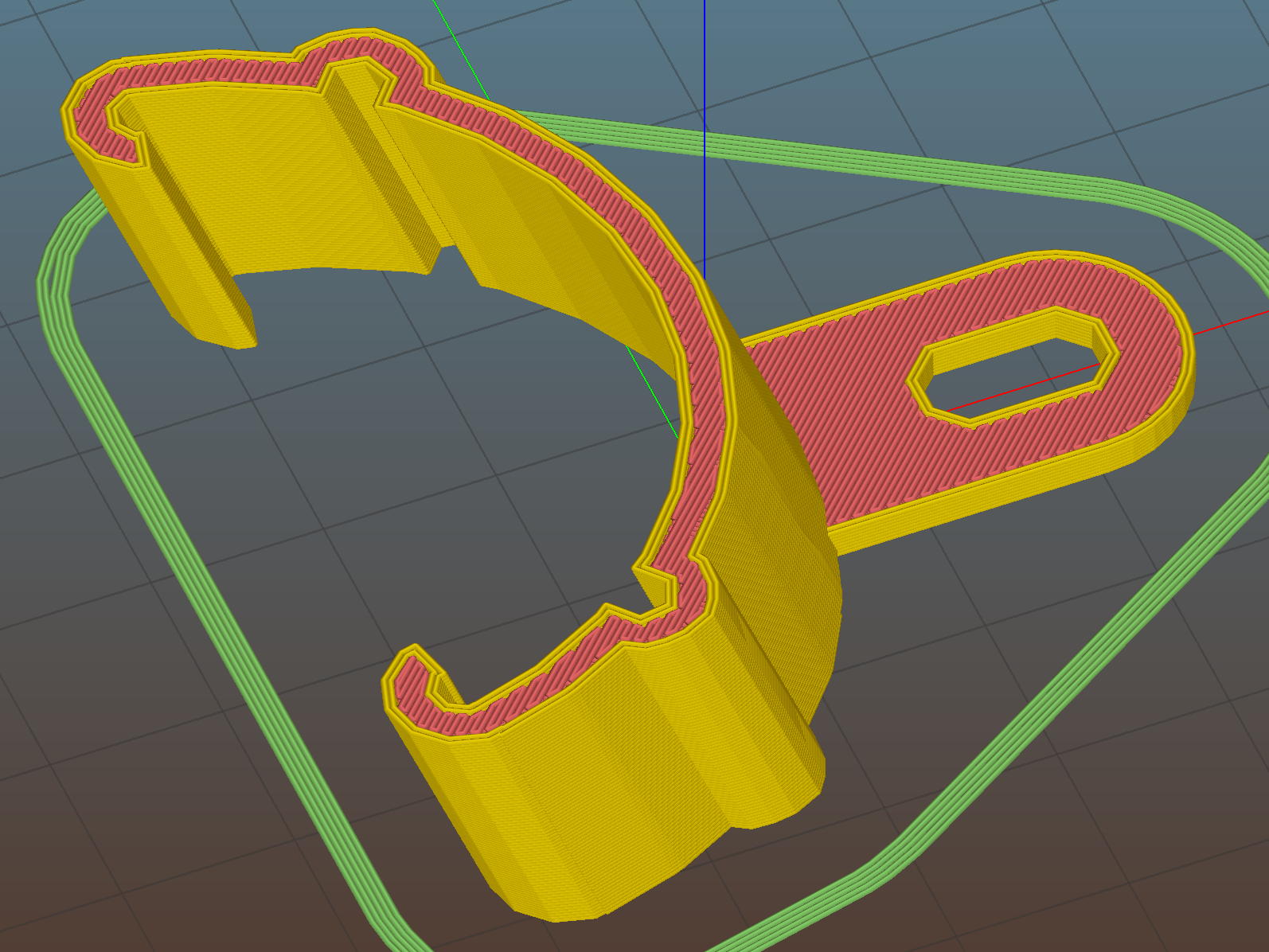
    After devoting far too long to thinking about how to angle the tab relative to the clip, I realized that I live in the future and can just angle the clip relative to the tab. Soooo, the solid model has a rakish tilt:

    Fender Clip - Slic3r preview
    Fender Clip – Slic3r preview

    The original design had a pair of strain relief struts where the tab meets the clip, but I figured I’ll add those after the PETG fractures.

    I mooched the small bumpouts along the arc from the original design; they provide a bit of stretch & bend so to ease the hooks around the fender.

    The hooks meet the clip with very slight discontinuities that, I think, come from slight differences between the 2D offset() operation and the circle() diameter; the usual 1/cos(180/numsides) trick was unavailing, so I tinkered until the answer came out right.

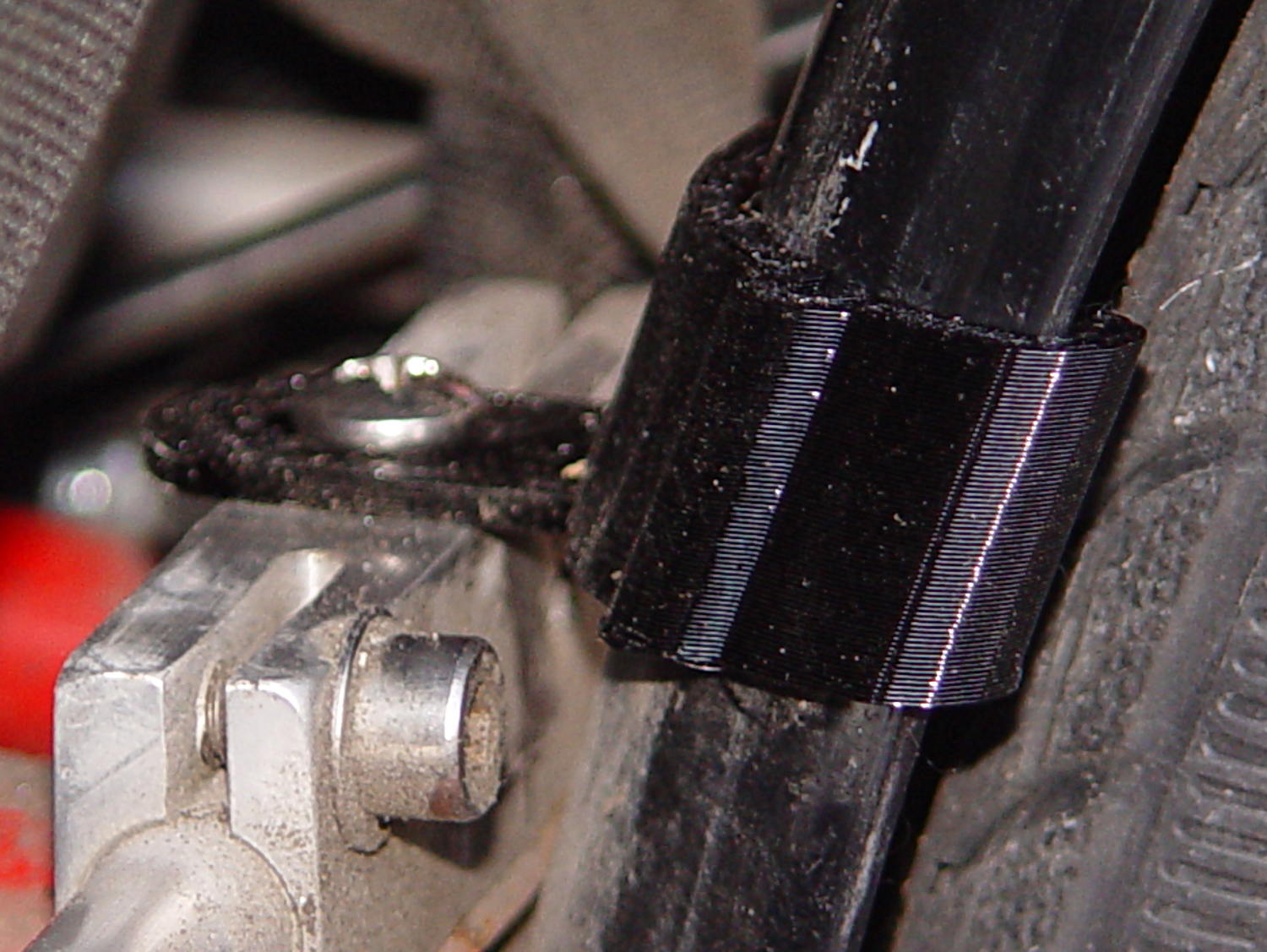
    Despite those stretchy bumps, it took three iterations, varying the chord height by about 1.5 mm, to securely snap those hooks onto the fender:

    Rear fender clip - 3D printed improvement
    Rear fender clip – 3D printed improvement

    Yeah, sorry ’bout the fuzzy focus on the screw head.

    It’s impossible to measure the chord height accurately enough in that position and I was not going to dismount the rear tire just to get a better measurement.

    You can see how the clip’s rakish tilt matches the fender’s slope, so the tab isn’t bent at all. It’ll probably break at the block the next time I jackknife the trailer, of course.

    I heroically resisted the urge to run off a lower fender mount.

    The OpenSCAD source code as a GitHub Gist:

    // Tour Easy rear fender clip
    // Ed Nisley KE4ZNU February 2017
    Layout = "Build"; // Build Profile Tab Clip
    //- Extrusion parameters must match reality!
    ThreadThick = 0.25;
    ThreadWidth = 0.40;
    HoleWindage = 0.2;
    Protrusion = 0.1; // make holes end cleanly
    inch = 25.4;
    function IntegerMultiple(Size,Unit) = Unit * ceil(Size / Unit);
    //———————-
    // Dimensions
    // special case: fender is exactly half a circle!
    FenderC = 47.0; // fender outside width = chord
    FenderM = 18.5; // height of chord
    FenderR = (pow(FenderM,2) + pow(FenderC,2)/4) / (2 * FenderM); // radius
    echo(str("Fender radius: ", FenderR));
    FenderD = 2*FenderR;
    FenderA = 2 * asin(FenderC / (2*FenderR));
    echo(str(" … arc: ",FenderA," deg"));
    FenderThick = 2.5; // fender thickness, assume dia of edge
    ClipHeight = 18.0; // top to bottom, ignoring rakish tilt
    ClipThick = 3.0; // thickness of clip around fender
    ClipD = FenderD; // ID of clip against
    ClipSides = 4 * 8; // polygon sides around clip circle
    BendReliefD = 2.5; // bend arch diameter
    BendReliefA = 2/3 * FenderA/2; // … angle from dead ahead
    BendReliefCut = 1.0; // factor to thin outside of bend
    TabAngle = -20; // angle from perpendicular to fender
    TabThick = 2.0;
    TabWidth = 15.0;
    ScrewOffset = 15.0; // screw center to fender along perpendicular
    ScrewD = 5.0;
    ScrewSlotLength = 2*ScrewD;
    //———————-
    // Useful routines
    module PolyCyl(Dia,Height,ForceSides=0) { // based on nophead's polyholes
    Sides = (ForceSides != 0) ? ForceSides : (ceil(Dia) + 2);
    FixDia = Dia / cos(180/Sides);
    cylinder(r=(FixDia + HoleWindage)/2,
    h=Height,
    $fn=Sides);
    }
    //———————-
    // Clip profile around fender
    // Centered on fender arc
    module Profile(HeightScale = 1) {
    linear_extrude(height=HeightScale*ClipHeight,convexity=5) {
    difference() {
    offset(r=ClipThick) // outside of clip
    union() {
    circle(d=ClipD,$fn=ClipSides);
    for (i=[-1,1])
    rotate(i*BendReliefA) {
    translate([ClipD/2 + BendReliefD/2,0,0])
    circle(d=BendReliefD,$fn=6);
    }
    }
    union() { // inside of clip
    circle(d=ClipD,$fn=ClipSides);
    for (i=[-1,1])
    rotate(i*BendReliefA) {
    translate([ClipD/2 + BendReliefCut*BendReliefD/2,0,0])
    circle(d=BendReliefD/cos(180/6),$fn=6);
    translate([ClipD/2,0,0])
    square([BendReliefCut*BendReliefD,BendReliefD],center=true);
    }
    }
    translate([(FenderR – FenderM – FenderD/2),0]) // trim ends
    square([FenderD,2*FenderD],center=true);
    }
    for (a=[-1,1]) // hooks around fender
    rotate(a*(FenderA/2))
    translate([FenderR – FenderThick/2,0]) {
    difference() {
    rotate(1*180/12)
    circle(d=FenderThick + 2*ClipThick,$fn=12);
    rotate(1*180/8)
    circle(d=FenderThick,$fn=8);
    rotate(a * -90)
    translate([0,-2*FenderThick,0])
    square(4*FenderThick,center=false);
    }
    }
    }
    }
    //———————-
    // Mounting tab
    module Tab() {
    linear_extrude(height=TabThick,convexity=3)
    difference() {
    hull() {
    circle(d=TabWidth,$fn=ClipSides);
    translate([(ScrewSlotLength – ScrewD)/2 + (FenderR + ScrewOffset),0,0])
    circle(d=TabWidth,$fn=ClipSides);
    }
    circle(d=ClipD,$fn=ClipSides); // remove fender arc
    hull() // screw slot
    for (i=[-1,1])
    translate([i*(ScrewSlotLength – ScrewD)/2 + (FenderR + ScrewOffset),0,0])
    rotate(180/8)
    circle(d=ScrewD/cos(180/8),$fn=8);
    }
    }
    //———————-
    // Combine at mounting angle
    module Clip() {
    difference() {
    union() {
    translate([-FenderR,0,0])
    Tab();
    rotate([0,TabAngle,0])
    translate([-FenderR,0,0])
    Profile(2); // scale upward for trimming
    }
    translate([0,0,-ClipHeight]) // trim bottom
    cube(2*[FenderD,FenderD,ClipHeight],center=true);
    translate([0,0,ClipHeight*cos(TabAngle)+ClipHeight]) // trim top
    cube(2*[FenderD,FenderD,ClipHeight],center=true);
    }
    }
    //———————-
    // Build it
    if (Layout == "Profile") {
    Profile();
    }
    if (Layout == "Tab") {
    Tab();
    }
    if (Layout == "Clip") {
    Clip();
    }
    if (Layout == "Build") {
    Clip();
    }

    The original doodle, with some measurements unable to withstand the test of time:

    Rear Fender Clip - measurement doodles
    Rear Fender Clip – measurement doodles
  • Cheap WS2812 LEDs: Test Fixture Mount

    Mounting the ungainly WS2812 LED test fixture seemed like a Good Idea to keep the electricity out of the usual conductive litter:

    WS2812 array test fixture - rear
    WS2812 array test fixture – rear

    The solid model shows more details:

    LED Test Fixture - solid model
    LED Test Fixture – solid model

    The power wires along the array edges slide into the rear (thinner) slot, with enough friction from a few gentle bends to hold the whole mess in place.

    The knockoff Arduino Nano rests on the recessed ledge in the pit, with M2 screws and washers at the corners holding it down (the PCB’s built-in holes might work with 1 mm or 0-90 screws, but that’s just crazy talk). I soldered the power wires directly to the coaxial jack pins under the PCB; they snake out to the LEDs through the little trench. There should be another cutout around the USB connector for in-situ programming, although the existing code works fine.

    The front (wider) slot holds a piece of translucent white acrylic to diffuse the light:

    WS2812 array test fixture - front flash
    WS2812 array test fixture – front flash

    It’s painfully bright: a few layers of neutral density filter would be appropriate for a desk toy.

    The array runs hot enough at MaxPWM = 255 to produce a gentle upward breeze.

    It looks even better without the flash:

    WS2812 array test fixture - front dark
    WS2812 array test fixture – front dark

    You’ll find many easier ways to get RGB LED panels, but that’s not the point here; I’m waiting for these things to die an unnatural death.

    The OpenSCAD source code as a GitHub Gist:

    // LED Test Fixture
    // Ed Nisley KE4ZNU – February 2017
    ClampFlange = true;
    Channel = false;
    //- Extrusion parameters – must match reality!
    ThreadThick = 0.25;
    ThreadWidth = 0.40;
    function IntegerMultiple(Size,Unit) = Unit * ceil(Size / Unit);
    Protrusion = 0.1;
    HoleWindage = 0.2;
    //- Screw sizes
    ID = 0;
    OD = 1;
    LENGTH = 2;
    Insert = [2.8,3.5,4.0]; // M2 threaded insert
    ScrewOD = 2.0;
    WasherOD = 5.0;
    //- Component sizes
    PCBSize = [18.0,43.5,1.6]; // microcontroller PCB
    PCBClear = 2*[ThreadWidth,ThreadWidth,0]; // clearance around board
    PCBShelf = [ThreadWidth,ThreadWidth,0]; // shelf under perimeter
    PCBCavity = PCBSize – PCBShelf + [0,0,2.5]; // support shelf around bottom parts
    LEDPanel = [70,40,4.0]; // lying flat, LEDs upward
    LEDWire = [LEDPanel[0],LEDPanel[1] + 2*5.0,2.0]; // power wires along sides
    Diffuser = [LEDPanel[0],LEDPanel[1] + 2*4.0,3.5];
    echo(str("Diffuser panel: ",Diffuser));
    WallThick = 8.0;
    BaseThick = 3*ThreadThick + Insert[LENGTH] + PCBCavity[2];
    Block = [3*WallThick + PCBSize[0] + LEDPanel[2] + Diffuser[2],
    2*WallThick + IntegerMultiple(max(PCBSize[1],LEDWire[1]),5),
    BaseThick + LEDPanel[0]];
    echo(str("Block: ",Block));
    CornerRadius = 5.0;
    NumSides = 4*5;
    //- Adjust hole diameter to make the size come out right
    module PolyCyl(Dia,Height,ForceSides=0) { // based on nophead's polyholes
    Sides = (ForceSides != 0) ? ForceSides : (ceil(Dia) + 2);
    FixDia = Dia / cos(180/Sides);
    cylinder(r=(FixDia + HoleWindage)/2,h=Height,$fn=Sides);
    }
    //- Build it
    difference() {
    hull() // main block with rounded corners
    for (i=[-1,1], j=[-1,1])
    translate([i*(Block[0]/2 – CornerRadius),j*(Block[1]/2 – CornerRadius),,0])
    cylinder(r=CornerRadius,h=Block[2],$fn=NumSides);
    translate([2*WallThick + PCBSize[0] – Block[0],
    0,
    (Block[2]/2 + BaseThick)])
    cube(Block + [0,2*Protrusion,0],center=true); // cut out over PCB
    translate([WallThick + (PCBSize + PCBClear)[0]/2 – Block[0]/2,
    0,
    0]) {
    translate([0,0,(BaseThick + (Protrusion – PCBSize[2])/2)])
    cube(PCBSize + PCBClear + [0,0,Protrusion],center=true); // PCB recess
    translate([0,0,(BaseThick + (Protrusion – PCBCavity[2])/2)])
    cube(PCBCavity + [0,0,Protrusion],center=true); // cavity under PCB
    translate([PCBSize[0]/2 + WallThick/2 – Protrusion/2,PCBSize[1]/2 – 15/2,BaseThick – PCBCavity[2]/2 + Protrusion/2])
    cube([WallThick + PCBShelf[0] + Protrusion,
    15,PCBCavity[2] + Protrusion],center=true); // wiring cutout
    for (i=[-1,1], j=[-1,1]) // screw inserts
    translate([i*(PCBSize[0] + ScrewOD)/2,j*(PCBSize[1] + ScrewOD)/2,-Protrusion])
    rotate(180/(2*6))
    PolyCyl(Insert[OD],BaseThick + 2*Protrusion,6);
    }
    resize([2*Block[0],0,LEDPanel[0] + Protrusion]) // LED panel outline
    translate([0,0,BaseThick])
    rotate([0,-90,0])
    translate([(LEDPanel[0] + Protrusion)/2,0,0])
    cube(LEDPanel + [Protrusion,0,0],center=true);
    translate([-Block[0]/2 + 2*WallThick + PCBSize[0] + LEDWire[2]/2 + 5*ThreadWidth,
    0,BaseThick]) // LED wiring recess
    rotate([0,-90,0])
    translate([(LEDWire[0] + Protrusion)/2,0,0])
    cube(LEDWire + [Protrusion,0,0],center=true);
    translate([Block[0]/2 – Diffuser[2]/2 – 5*ThreadWidth,0,BaseThick]) // diffuser
    rotate([0,-90,0])
    translate([(Diffuser[0] + Protrusion)/2,0,0])
    cube(Diffuser + [Protrusion,0,0],center=true);
    }
  • Bandsaw Worklight: LED Cable Clips

    Adapting the sewing machine cable clips for larger USB cables:

    LED Cable Clips - solid model
    LED Cable Clips – solid model

    The calculation positioning the posts wasn’t quite right; they now touch the cable OD at their midline and converge slightly overhead to retain it.

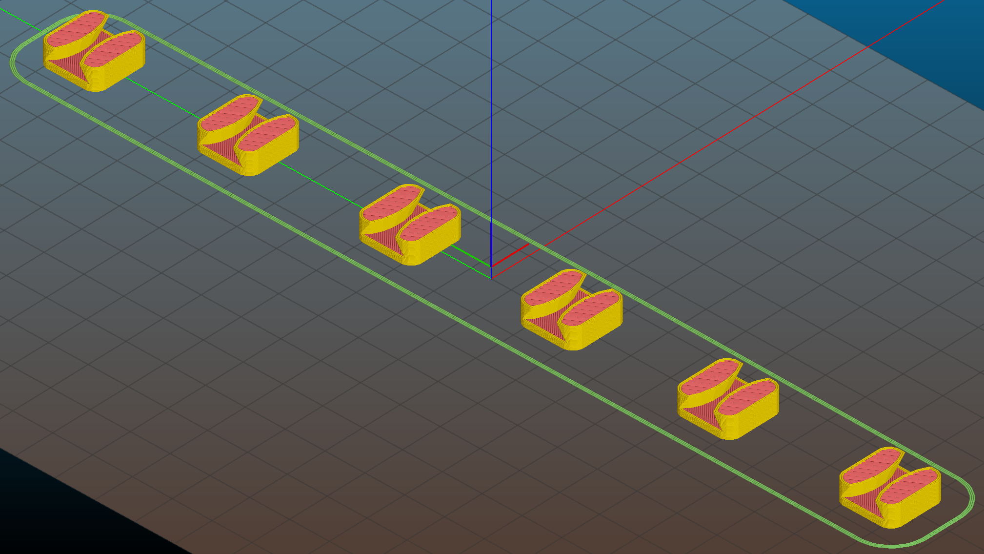
    They’re great candidates for sequential printing:

    LED Cable Clips - Slic3r - sequential print
    LED Cable Clips – Slic3r – sequential print

    With the basement at 14 °C, any cooling is too much: the platform heater can’t keep the bed above the thermal cutout temperature, the firmware concludes the thermistor has failed, and shuts the printer off. So I popped the four finished clips off the platform, removed the skirt, unplugged the fan, rebooted that sucker, and restarted the print.

    One clip in the front keeps the cable away from the power switch and speed control directly below the gooseneck mount:

    USB Gooseneck Mount - cable clip
    USB Gooseneck Mount – cable clip

    A few clips in the back route the cable from the COB LED epoxied directly onto the bandsaw frame away from the motor enclosure:

    Bandsaw platform COB LED - cable clips
    Bandsaw platform COB LED – cable clips

    They’re mounted on double-sided foam tape. The COB LED on the frame isn’t anything to write home about, but you can see the foam tape peeking out around the clip base:

    Bandsaw platform COB LED
    Bandsaw platform COB LED

    Unlike those LED filaments, it seems you can gently bend the aluminum substrate under a COB LED.

    The bandsaw platform now has plenty of light: a fine upgrade!

    Yeah, you can buy stick-on cable anchors, but what’s the fun in that? These fit exactly, hold securely, and work just fine.

    The OpenSCAD source code as a GitHub Gist:

    // LED Cable Clips
    // Ed Nisley – KE4ZNU – October 2014
    // February 2017 – adapted for USB cables
    Layout = "Show"; // Show Build
    //- Extrusion parameters must match reality!
    ThreadThick = 0.25;
    ThreadWidth = 0.40;
    HoleWindage = 0.2; // extra clearance
    Protrusion = 0.1; // make holes end cleanly
    function IntegerMultiple(Size,Unit) = Unit * ceil(Size / Unit);
    //———————-
    // Dimensions
    Base = [15.0,15.0,6*ThreadThick]; // base over sticky square
    CableOD = 3.8;
    BendRadius = 5.0;
    CornerRadius = Base[0]/5;
    CornerSides = 4*4;
    NumSides = 6*3;
    //– Oval clip with central passage
    module OvalPass() {
    intersection() {
    hull()
    for (i=[-1,1], j=[-1,1])
    translate([i*(Base[0]/2 – CornerRadius),j*(Base[1]/2 – CornerRadius),0])
    rotate(180/CornerSides)
    cylinder(r=CornerRadius,h=Base[2] + 1.00*CableOD,$fn=CornerSides,center=false);
    union() {
    translate([0,0,Base[2]/2]) // oversize mount base
    scale([2,2,1])
    cube(Base,center=true);
    for (j=[-1,1]) // bending ovals
    translate([0,j*(Base[1]/2 – 0.125*(Base[1] – CableOD)/2),(Base[2] – Protrusion)])
    resize([Base[0]/0.75,0,0])
    cylinder(d1=0.75*(Base[1]-CableOD),
    d2=(Base[1]-CableOD)/cos(0*180/NumSides),
    h=(CableOD + Protrusion),
    center=false,$fn=NumSides);
    }
    }
    if (Layout == "Show")
    color("Red",0.3)
    translate([0,0,Base[2] + CableOD/2])
    rotate([0,90,0])
    cylinder(d=CableOD,h=2*Base[0],center=true,$fn=48);
    }
    //———————-
    // Build it
    OvalPass();
  • Bandsaw Worklight: USB Gooseneck Mount

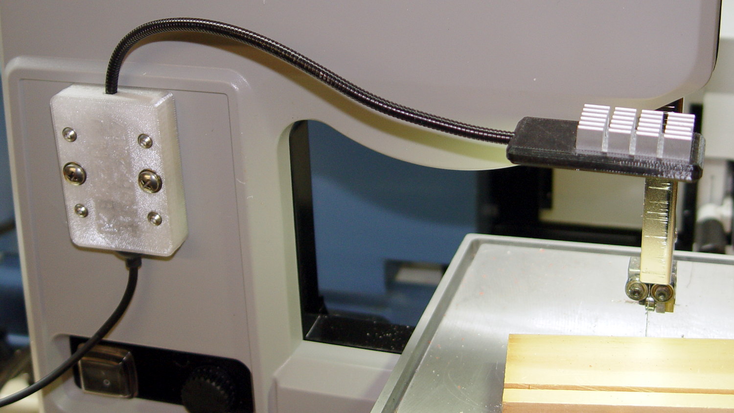
    The bandsaw now sports a chunky mount for its gooseneck light:

    USB Gooseneck Mount - on bandsaw
    USB Gooseneck Mount – on bandsaw

    The gooseneck ends in a USB Type-A plug, so an ordinary USB extension cable can connect it to the hacked hub supplying 9 VDC:

    USB Gooseneck Mount - interior
    USB Gooseneck Mount – interior

    The plastic came from a slightly earlier version of the solid model, with one foam pad under the gooseneck’s USB plug to soak up the clearance. The four smaller holes, with M3 brass inserts visible in the bottom half (on the right), clamp the gooseneck connector in place against the foam; you could push it out if you were really determined, but you’d have to be really determined.

    If I ever build another one, it’ll sandwich the plug between opposing pads:

    USB Gooseneck Connector Mount - Slic3r preview
    USB Gooseneck Connector Mount – Slic3r preview

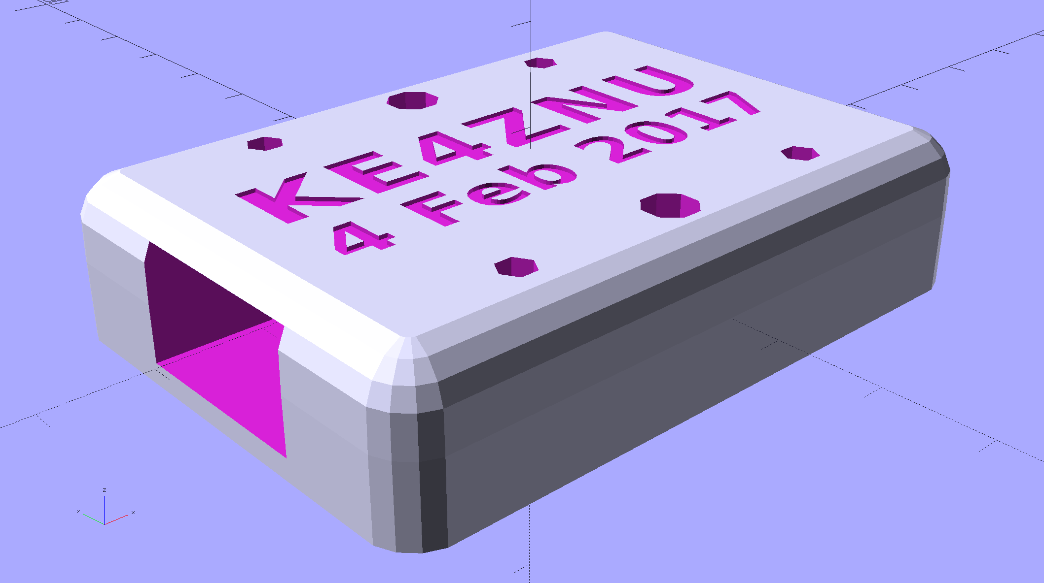
    The lettering on the block stands out much better in the solid model:

    USB Gooseneck Connector Mount - solid model - overview
    USB Gooseneck Connector Mount – solid model – overview

    Obviously, I need help with the stylin’ thing. This looks better, but with terrible overhangs for printing in the obvious no-support orientation:

    USB Gooseneck Connector Mount - solid model - rounded top
    USB Gooseneck Connector Mount – solid model – rounded top

    Anyhow, the USB extension cable (on the left) has plenty of clearance and pulls straight out of the housing, so I can remove the bandsaw cover without unwiring:

    USB Gooseneck Mount - assembled
    USB Gooseneck Mount – assembled

    The LED ticks along at 40 °C in a 14 °C basement, suggesting a thermal coefficient around 14 °C/W. Even in the summer months, with the basement around 25 °C, there’s no risk of PETG softening at 50 °C.

    I’ll epoxy a similar 1.8 W COB LED onto the curve of the bandsaw frame where it can shine on the left and rear part of the table; it doesn’t even need a case.

    The OpenSCAD source code as a GitHub Gist:

    // Gooseneck lamp for MicroMark bandsaw
    // Ed Nisley KE4ZNU
    // February 2017
    Layout = "Mount"; // Mount Show Build
    Gap = 5; // distance between halves for Show
    //- Extrusion parameters must match reality!
    ThreadThick = 0.25;
    ThreadWidth = 0.40;
    HoleWindage = 0.2;
    Protrusion = 0.1; // make holes end cleanly
    inch = 25.4;
    function IntegerMultiple(Size,Unit) = Unit * ceil(Size / Unit);
    //———————-
    // Dimensions
    Tap10_32 = 0.159 * inch;
    Clear10_32 = 0.190 * inch;
    Head10_32 = 0.373 * inch;
    Head10_32Thick = 0.110 * inch;
    Nut10_32Dia = 0.433 * inch;
    Nut10_32Thick = 0.130 * inch;
    Washer10_32OD = 0.381 * inch;
    Washer10_32ID = 0.204 * inch;
    ID = 0; // for round things
    OD = 1;
    LENGTH = 2;
    Insert = [3.0,4.9,2*ThreadThick + IntegerMultiple(4.2,ThreadThick)]; // M3 short brass insert
    CornerRadius = 5.0; // rounded mount block corners for pretty
    CornerSides = 4*4;
    RoundedTop = true; // true for fancy smooth top edges
    USBPlug = [39.0,16.0,8.3]; // plug, X from base of plug
    USBSocket = [28.0,20.0,11.5]; // USB extension, X from tip of socket
    USBMating = [-12.0,0,0]; // offset of plug base relative to block center
    Foam = [35.0,10.0,2.0 – 1.0]; // foam pad to secure USB plug (Z = thickness – compression)
    GooseneckOD = 5.0; // flexy gooseneck diameter
    MountScrewOC = 35.0; // make simple screw hole spacing for bandsaw case
    MountBlock = [10*round((USBPlug[0] + USBSocket[0] + 5.0)/10),
    10*round((MountScrewOC + Washer10_32OD + 5.0)/10),
    // 2*6*ThreadThick + IntegerMultiple(max(USBPlug[2],USBSocket[2]),ThreadThick)];
    16.0]; // thickness = 16 mm M3x0.5 button head screw
    echo(str("Block size: ",MountBlock));
    LegendDepth = 2*ThreadThick; // lettering depth
    //———————-
    // Useful routines
    module PolyCyl(Dia,Height,ForceSides=0) { // based on nophead's polyholes
    Sides = (ForceSides != 0) ? ForceSides : (ceil(Dia) + 2);
    FixDia = Dia / cos(180/Sides);
    cylinder(r=(FixDia + HoleWindage)/2,
    h=Height,
    $fn=Sides);
    }
    //– Mount
    module Mount() {
    difference() {
    hull()
    if (RoundedTop) {
    for (i=[-1,1], j=[-1,1])
    translate([i*(MountBlock[0]/2 – CornerRadius),j*(MountBlock[1]/2 – CornerRadius),0]) {
    translate([0,0,-MountBlock[2]/2])
    rotate(180/CornerSides)
    cylinder(r=CornerRadius,h=MountBlock[2]/2,$fn=CornerSides,center=false);
    translate([0,0,MountBlock[2]/2 – CornerRadius])
    rotate(180/CornerSides)
    sphere(r=CornerRadius,$fn=CornerSides,center=true);
    }
    }
    else {
    for (i=[-1,1], j=[-1,1])
    translate([i*(MountBlock[0]/2 – CornerRadius),j*(MountBlock[1]/2 – CornerRadius),0])
    rotate(180/CornerSides)
    cylinder(r=CornerRadius,h=MountBlock[2],$fn=CornerSides,center=true);
    }
    for (j=[-1,1]) // screws into bandsaw case
    translate([0,j*MountScrewOC/2,-(MountBlock[2]/2 + Protrusion)])
    rotate(180/8)
    PolyCyl(Clear10_32,(MountBlock[2] + 2*Protrusion),8);
    for (i=[-1,1], j=[-1,1]) { // clamp screws
    translate([i*MountBlock[0]/4,j*MountScrewOC/2,-MountBlock[2]])
    PolyCyl(Insert[ID],2*MountBlock[2],6); // clearance
    translate([i*MountBlock[0]/4,j*MountScrewOC/2,-(MountBlock[2]/2 + Protrusion)])
    PolyCyl(Insert[OD],Insert[LENGTH] + Protrusion,6); // inserts
    }
    rotate([0,90,0]) // gooseneck flexy cable
    rotate(180/6)
    PolyCyl(GooseneckOD,MountBlock[0],6);
    translate([USBPlug[0]/2,0,0] + USBMating – [Protrusion/2,0,0]) // USB plug outline
    cube(USBPlug + [Protrusion,0,0],center=true);
    translate([-USBSocket[0]/2,0,0] + USBMating) // USB socket outline
    cube(USBSocket,center=true);
    translate([(Foam[0]/2 + 5*ThreadWidth),0,-(Foam[2]/2 + USBPlug[2]/2)] + USBMating – [Protrusion,0,-Protrusion]/2) // foam padding recess
    cube(Foam + [Protrusion,0,Protrusion],center=true); // foam packing
    translate([(Foam[0]/2 + 5*ThreadWidth),0, (Foam[2]/2 + USBPlug[2]/2)] + USBMating – [Protrusion,0, Protrusion]/2) // foam padding recess
    cube(Foam + [Protrusion,0,Protrusion],center=true);
    render(convexity=5)
    translate([0,0,MountBlock[2]/2 – LegendDepth])
    linear_extrude(height=LegendDepth + Protrusion) {
    translate([0,5,0])
    text(text="KE4ZNU",size=8,spacing=1.10,font="Bitstream Vera Sans:style=Bold",valign="center",halign="center");
    translate([0,-5,0])
    text(text="4 Feb 2017",size=6,spacing=1.05,font="Bitstream Vera Sans:style=Bold",valign="center",halign="center");
    }
    }
    }
    //———————-
    // Build it
    if (Layout == "Mount") {
    Mount();
    }
    if (Layout == "Show") {
    translate([0,0,-Gap/2])
    difference() {
    Mount();
    translate([0,0,MountBlock[2]])
    cube(2*MountBlock,center=true);
    }
    translate([0,0,Gap/2])
    difference() {
    Mount();
    translate([0,0,-MountBlock[2]])
    cube(2*MountBlock,center=true);
    }
    }
    if (Layout == "Build") {
    translate([0,0.6*MountBlock[1],MountBlock[2]/2])
    difference() {
    Mount();
    translate([0,0,MountBlock[2]])
    cube(2*MountBlock,center=true);
    }
    translate([0,-0.6*MountBlock[1],MountBlock[2]/2])
    rotate([180,0,0])
    difference() {
    Mount();
    translate([0,0,-MountBlock[2]])
    cube(2*MountBlock,center=true);
    }
    }
  • Proto Board Holders: 80×120 mm

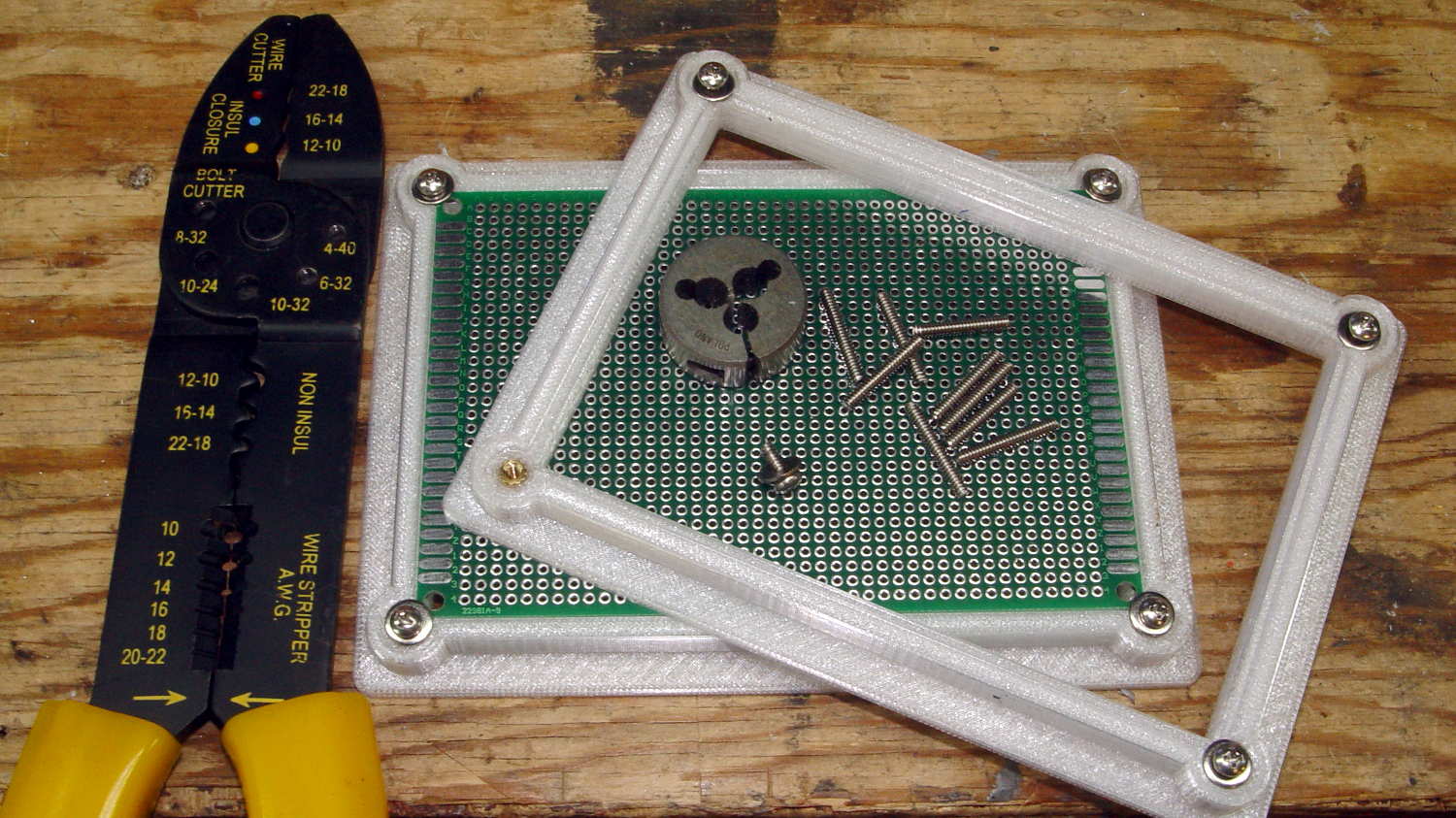
    Another stack of proto boards arrived, this time 80×120 mm, and I ran off another pair of holders:

    Proto Board Holder - 80x120 - tooling
    Proto Board Holder – 80×120 – tooling

    Not wanting to, ahem, screw around with the lathe, the screws got themselves shortened the old-fashioned way: by hand, with the screw cutter, then filed and passed through a 4-40 die to clean up the threads.

    Bah!