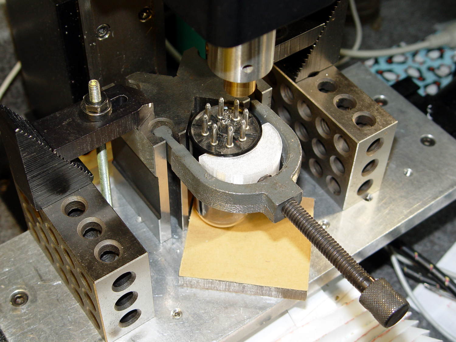
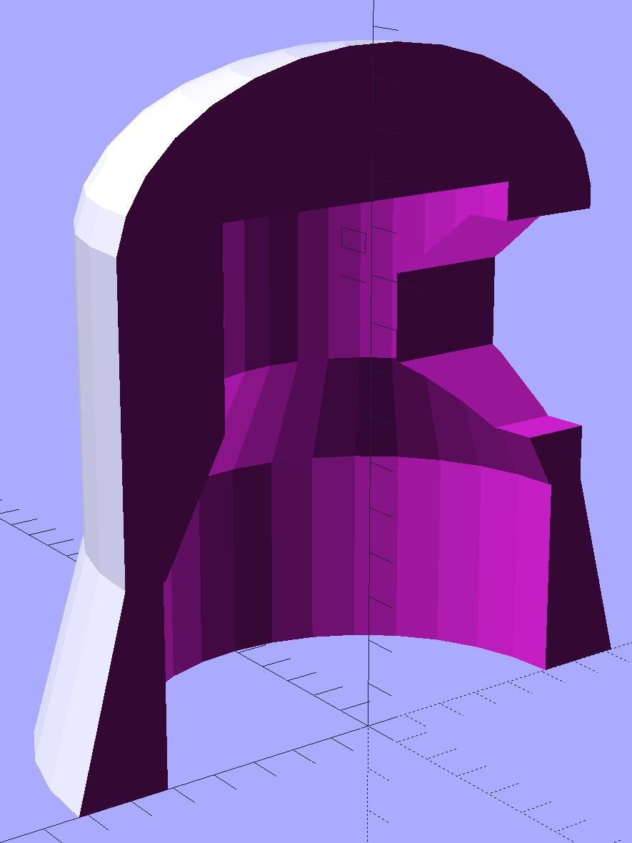
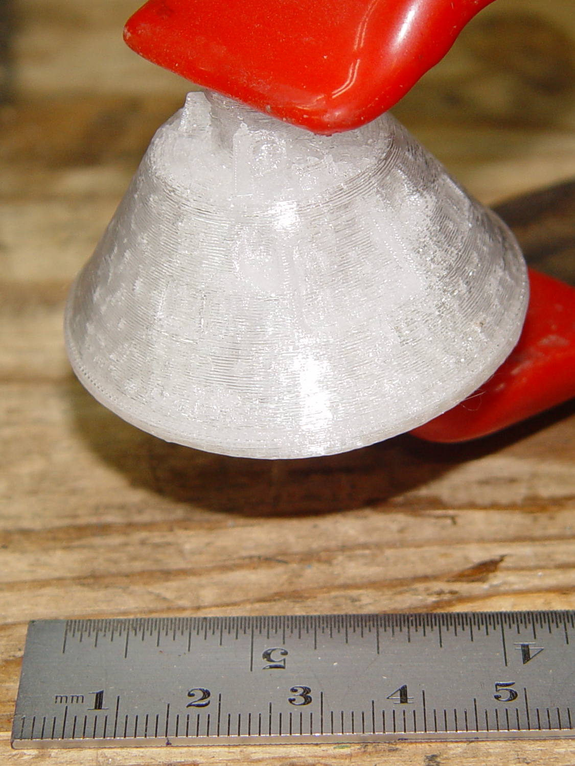
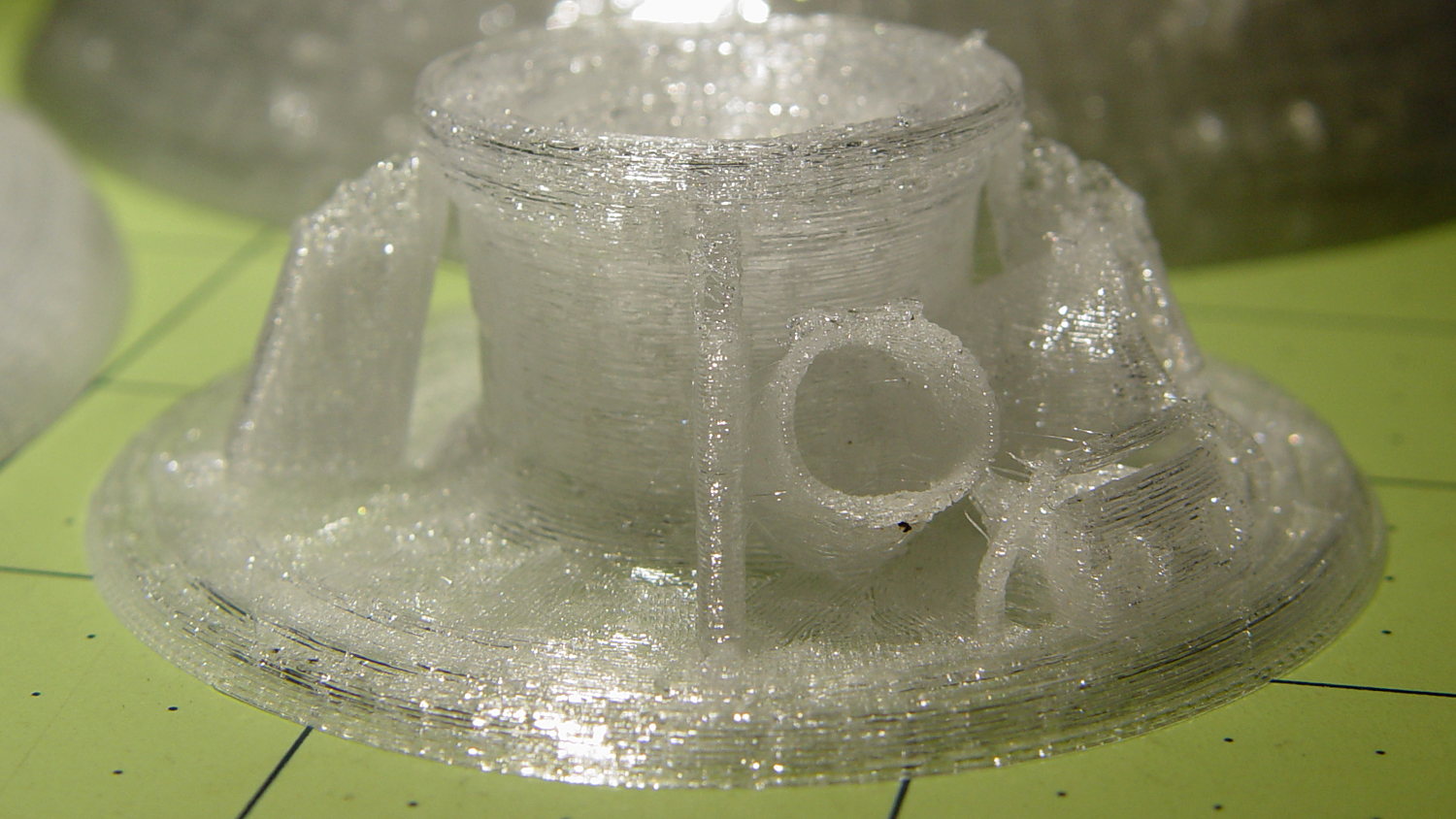
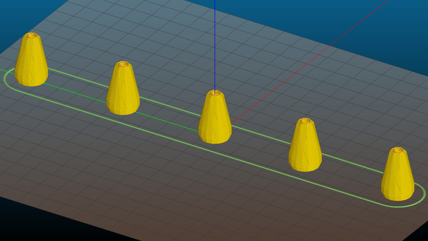
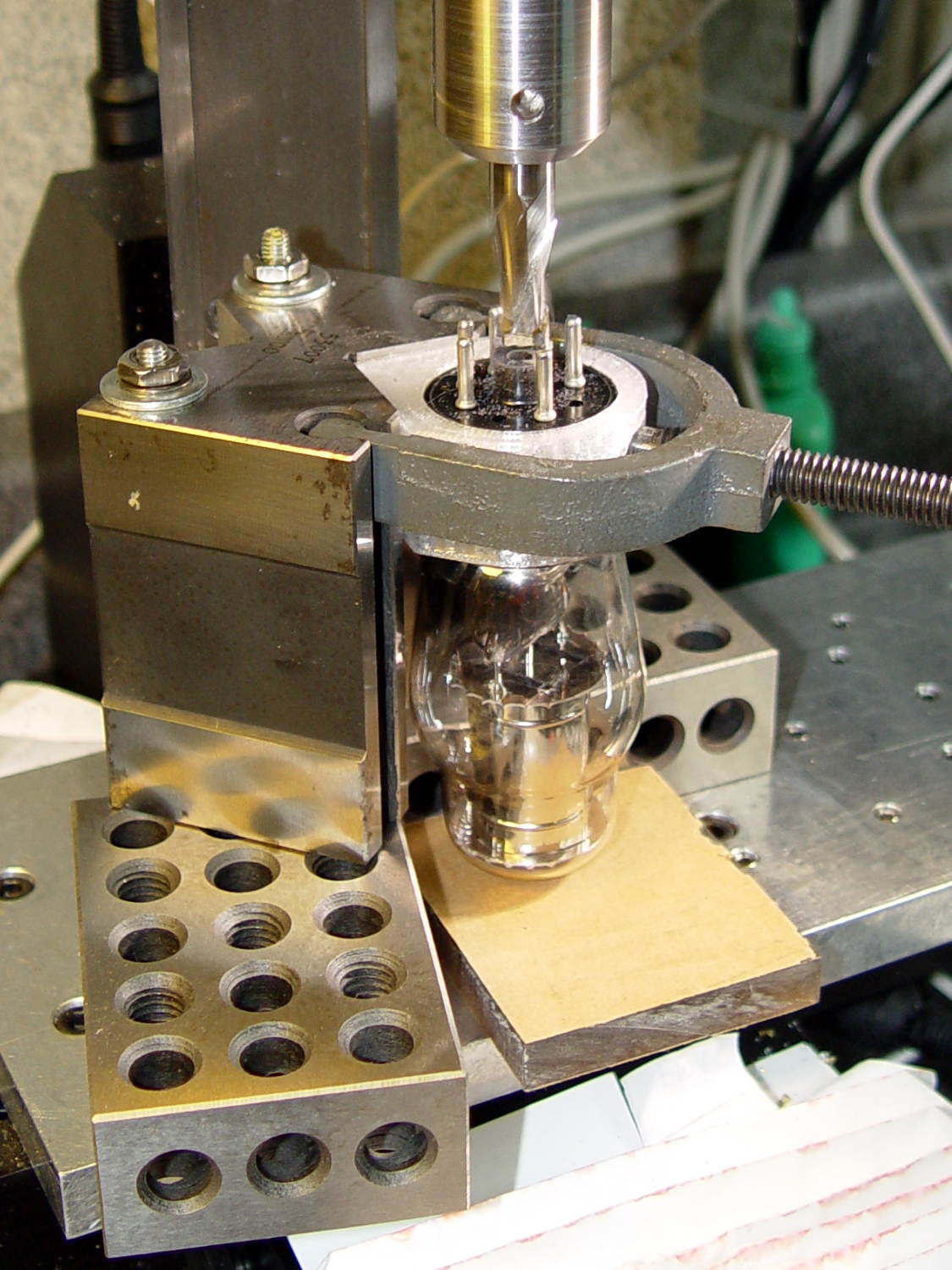
In order to clamp the tube in a V-block, the clamp must position the tube’s centerline so the envelope will clear the V groove, thusly:
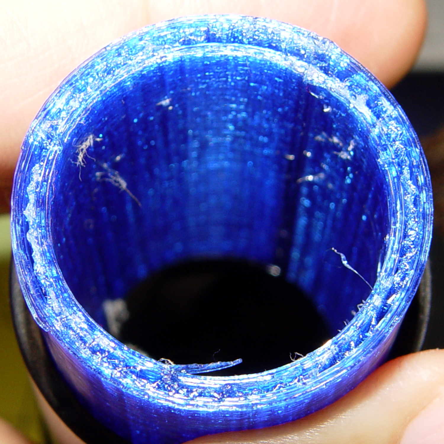
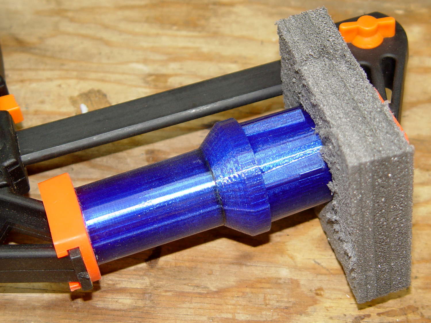
The clamp now extends into the V-block and surrounds the entire Bakelite tube base:

The little divot captures the clamp screw and the slot lets the whole affair compress just enough to firmly squeeze the entire tube base.
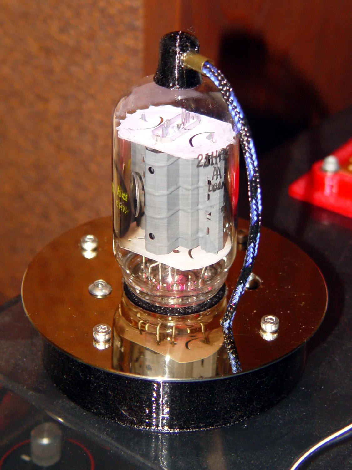
The tube data table now includes columns for the envelope OD and the base OD, although only the 0D3 (and similar) Octal tubes in my collection have a bulging envelope and a smaller base. You can build clamps for cylindrical glass tubes if you like; I don’t vouch for the accuracy of the table contents.
For whatever it’s worth, the 6SN7GTB tube I started with has a 32 mm Bakelite base and the 0D3 tube has a 29 mm base. That should probably justify two separate entries in the table, but I’m making this up as I go along.
The OpenSCAD source code as a GitHub Gist:
| // Vacuum Tube LED Lights | |
| // Ed Nisley KE4ZNU February … September 2016 | |
| Layout = "TubeClamp"; // Cap LampBase USBPort Bushings | |
| // Socket(s) Cap (Build)FinCap Platter[Base|Fixture] | |
| // TubeClamp PlatterParts | |
| DefaultSocket = "Octal"; | |
| Section = false; // cross-section the object | |
| Support = true; | |
| //- Extrusion parameters must match reality! | |
| ThreadThick = 0.25; | |
| ThreadWidth = 0.40; | |
| HoleWindage = 0.2; | |
| Protrusion = 0.1; // make holes end cleanly | |
| inch = 25.4; | |
| function IntegerMultiple(Size,Unit) = Unit * ceil(Size / Unit); | |
| //———————- | |
| // Dimensions | |
| // https://en.wikipedia.org/wiki/Tube_socket#Summary_of_Base_Details | |
| // punch & screw OC modified for drive platter chassis plate | |
| // platter = 25 mm ID | |
| // CD = 15 mm ID with raised ring at 37 mm, needs screw head clearance | |
| T_NAME = 0; // common name | |
| T_NUMPINS = 1; // total, with no allowance for keying | |
| T_PINBCD = 2; // tube pin circle diameter | |
| T_PINOD = 3; // … diameter | |
| T_PINLEN = 4; // … length (must also clear evacuation tip / spigot) | |
| T_HOLEOD = 5; // nominal panel hole from various sources | |
| T_PUNCHOD = 6; // panel hole optimized for inch-size Greenlee punches | |
| T_BASEOD = 7; // base OD | |
| T_BULBOD = 8; // glass envelope OD | |
| T_PIPEOD = 9; // light pipe from LED to tube base (clear evac tip / spigot) | |
| T_SCREWOC = 10; // mounting screw holes | |
| T_PLATECAP = 11; // nonzero to print a plate cap | |
| // Name pins BCD dia length hole punch base bulb pipe screw cap | |
| TubeData = [ | |
| ["Mini7", 8, 9.53, 1.016, 7.0, 16.0, 25.0, 18.0, 18.0, 5.0, 35.0, 0], // punch 11/16, screw 22.5 OC | |
| // ["Octal", 8, 17.45, 2.36, 11.0, 36.2, (8 + 1)/8 * inch, 32.0, 38.1, 11.5, 47.0, 1], // screw 39.0 OC, base 32 or 39 | |
| ["Octal", 8, 17.45, 2.36, 11.0, 36.2, 25.0, 29.0, 38.1, 11.5, 42.0, 1], // platter + 4 mm screws | |
| ["Noval", 10, 11.89, 1.1016, 7.0, 22.0, 25.0, 21.0, 21.0, 7.5, 35.0, 0], // punch 7/8, screw 28.0 OC | |
| ["Magnoval", 10, 17.45, 1.27, 9.0, 29.7, (4 + 1)/4 * inch, 46.0, 46.0, 12.4, 38.2, 0], // similar to Novar | |
| // ["Duodecar", 13, 19.10, 1.05, 9.0, 32.0, (4 + 1)/4 * inch, 38.0, 38.0, 12.5, 47.0, 1], // screw was 39.0 OC | |
| ["Duodecar", 13, 19.10, 1.05, 9.0, 25.0, 25.0, 38.0, 38.0, 12.5, 42.0, 1], // fit un-punched drive platter | |
| ]; | |
| ID = 0; | |
| OD = 1; | |
| LENGTH = 2; | |
| Pixel = [7.0,10.0,3.0]; // ID = contact patch, OD = PCB dia, LENGTH = overall thickness | |
| PixelRecessHeight = 1.55*Pixel[LENGTH]; // enough of a recess to allow for tube top curvature | |
| SocketNut = // socket mounting: threaded insert or nut recess | |
| // [3.5,5.2,7.2] // 6-32 insert | |
| [4.0,6.0,5.9] // 4 mm short insert | |
| ; | |
| NutSides = 8; | |
| SocketShim = 2*ThreadThick; // between pin holes and pixel top | |
| SocketFlange = 1.5; // rim around socket below punchout | |
| PanelThick = 1.5; // socket extension through punchout | |
| FinCutterOD = 1/8 * inch; | |
| FinCapSize = [(Pixel[OD] + 2*FinCutterOD),30.0,(10.0 + 2*Pixel[LENGTH])]; | |
| USBPCB = | |
| // [28,16,6.5] // small Sparkfun knockoff | |
| [36,18 + 1,5.8 + 0.4] // Deek-Robot fake FTDI with ISP header | |
| ; | |
| Platter = [25.0,95.0,1.26]; // hard drive platter dimensions | |
| PlatterSides = 8*4; // polygon approximation | |
| //———————- | |
| // Useful routines | |
| module PolyCyl(Dia,Height,ForceSides=0) { // based on nophead's polyholes | |
| Sides = (ForceSides != 0) ? ForceSides : (ceil(Dia) + 2); | |
| FixDia = Dia / cos(180/Sides); | |
| cylinder(d=(FixDia + HoleWindage),h=Height,$fn=Sides); | |
| } | |
| //———————- | |
| // Tube cap | |
| CapTube = [4.0,3/16 * inch,10.0]; // brass tube for flying lead to cap LED | |
| CapSize = [Pixel[ID],(Pixel[OD] + 2.0),(CapTube[OD] + 2.0*Pixel[LENGTH])]; | |
| CapSides = 8*4; | |
| SkirtOD = CapSize[OD] + 4*ThreadWidth; | |
| CapTubeHeight = (CapSize[LENGTH] + PixelRecessHeight)/2; | |
| CapTubeBossOD = 1*ThreadWidth + 2*(CapTubeHeight – PixelRecessHeight)/cos(180/8); | |
| module Cap() { | |
| difference() { | |
| union() { | |
| cylinder(d=CapSize[OD],h=(CapSize[LENGTH]),$fn=CapSides); // main cap body | |
| translate([0,0,CapSize[LENGTH]]) // rounded top | |
| scale([1.0,1.0,0.65]) | |
| sphere(d=CapSize[OD]/cos(180/CapSides),$fn=CapSides); // cos() fixes slight undersize vs cylinder | |
| cylinder(d1=SkirtOD,d2=CapSize[OD],h=PixelRecessHeight,$fn=CapSides); // skirt | |
| translate([0,-SkirtOD/2,CapTubeHeight]) // boss around brass tube | |
| rotate([-90,0,0]) | |
| rotate(180/8) | |
| cylinder(d=CapTubeBossOD,h=CapTube[LENGTH],$fn=8); | |
| } | |
| translate([0,0,-Protrusion]) // bore for wiring to LED | |
| PolyCyl(CapSize[ID],(CapSize[LENGTH] + 3*ThreadThick + Protrusion),CapSides); | |
| translate([0,0,-Protrusion]) // PCB recess with clearance for tube dome | |
| PolyCyl(Pixel[OD],(PixelRecessHeight + Protrusion),CapSides); | |
| translate([0,0,(PixelRecessHeight – Protrusion)]) // small step + cone to retain PCB | |
| cylinder(d1=(Pixel[OD]/cos(180/CapSides) + HoleWindage),d2=Pixel[ID],h=(Pixel[LENGTH] + Protrusion),$fn=CapSides); | |
| translate([0,0,CapTubeHeight]) // hole for brass tube holding wire loom | |
| rotate([90,0,0]) rotate(180/8) | |
| PolyCyl(CapTube[OD],CapSize[OD],8); | |
| } | |
| } | |
| //———————- | |
| // Heatsink tube cap | |
| module FinCap() { | |
| CableOD = 3.5; // cable + braid diameter | |
| BulbOD = 3.75 * inch; // bulb OD; use 10 inches for flat | |
| echo(str("Fin Cutter: ",FinCutterOD)); | |
| FinSides = 2*4; | |
| BulbRadius = BulbOD / 2; | |
| BulbDepth = BulbRadius – sqrt(pow(BulbRadius,2) – pow(FinCapSize[OD],2)/4); | |
| echo(str("Bulb OD: ",BulbOD," recess: ",BulbDepth)); | |
| NumFins = floor(PI*FinCapSize[ID] / (2*FinCutterOD)); | |
| FinAngle = 360 / NumFins; | |
| echo(str("NumFins: ",NumFins," angle: ",FinAngle," deg")); | |
| difference() { | |
| union() { | |
| cylinder(d=FinCapSize[ID],h=FinCapSize[LENGTH],$fn=2*NumFins); // main body | |
| for (i = [0:NumFins – 1]) // fins | |
| rotate(i * FinAngle) | |
| hull() { | |
| translate([FinCapSize[ID]/2,0,0]) | |
| rotate(180/FinSides) | |
| cylinder(d=FinCutterOD,h=FinCapSize[LENGTH],$fn=FinSides); | |
| translate([(FinCapSize[OD] – FinCutterOD)/2,0,0]) | |
| rotate(180/FinSides) | |
| cylinder(d=FinCutterOD,h=FinCapSize[LENGTH],$fn=FinSides); | |
| } | |
| rotate(FinAngle/2) // cable entry boss | |
| translate([FinCapSize[ID]/2,0,FinCapSize[LENGTH]/2]) | |
| cube([FinCapSize[OD]/4,FinCapSize[OD]/4,FinCapSize[LENGTH]],center=true); | |
| } | |
| for (i = [1:NumFins – 1]) // fin inner gullets, omit cable entry side | |
| rotate(i * FinAngle + FinAngle/2) // joint isn't quite perfect, but OK | |
| translate([FinCapSize[ID]/2,0,-Protrusion]) | |
| rotate(0*180/FinSides) | |
| cylinder(d=FinCutterOD/cos(180/FinSides),h=(FinCapSize[LENGTH] + 2*Protrusion),$fn=FinSides); | |
| translate([0,0,-Protrusion]) // PCB recess | |
| PolyCyl(Pixel[OD],(PixelRecessHeight + Protrusion),FinSides); | |
| PolyCyl(Pixel[ID],(FinCapSize[LENGTH] – 3*ThreadThick),FinSides); // bore for LED wiring | |
| translate([0,0,(FinCapSize[LENGTH] – 3*ThreadThick – 2*CableOD/(2*cos(180/8)))]) // cable inlet | |
| rotate(FinAngle/2) rotate([0,90,0]) rotate(180/8) | |
| PolyCyl(CableOD,FinCapSize[OD],8); | |
| if (BulbOD <= 10.0 * inch) // curve for top of bulb | |
| translate([0,0,-(BulbRadius – BulbDepth + 2*ThreadThick)]) // … slightly flatten tips | |
| sphere(d=BulbOD,$fn=16*FinSides); | |
| } | |
| } | |
| //———————- | |
| // Aperture for USB-to-serial adapter snout | |
| // These are all magic numbers, of course | |
| module USBPort() { | |
| translate([0,USBPCB[0]]) | |
| rotate([90,0,0]) | |
| linear_extrude(height=USBPCB[0]) | |
| polygon(points=[ | |
| [0,0], | |
| [USBPCB[1]/2,0], | |
| [USBPCB[1]/2,0.5*USBPCB[2]], | |
| [USBPCB[1]/3,USBPCB[2]], | |
| [-USBPCB[1]/3,USBPCB[2]], | |
| [-USBPCB[1]/2,0.5*USBPCB[2]], | |
| [-USBPCB[1]/2,0], | |
| ]); | |
| } | |
| //———————- | |
| // Box for Leviton ceramic lamp base | |
| module LampBase() { | |
| Insert = [3.5,5.2,7.2]; // 6-32 brass insert to match standard electrical screws | |
| Bottom = 3.0; | |
| Base = [4.0*inch,4.5*inch,20.0 + Bottom]; | |
| Sides = 12*4; | |
| Retainer = [3.5,11.0,1.0]; // flat fiber washer holding lamp base screws in place | |
| StudSides = 8; | |
| StudOC = 3.5 * inch; | |
| Stud = [Insert[OD], // insert for socket screws | |
| min(15.0,1.5*(Base[ID] – StudOC)/cos(180/StudSides)), // OD = big enough to merge with walls | |
| (Base[LENGTH] – Retainer[LENGTH])]; // leave room for retainer | |
| union() { | |
| difference() { | |
| rotate(180/Sides) | |
| cylinder(d=Base[OD],h=Base[LENGTH],$fn=Sides); | |
| rotate(180/Sides) | |
| translate([0,0,Bottom]) | |
| cylinder(d=Base[ID],h=Base[LENGTH],$fn=Sides); | |
| translate([0,-Base[OD]/2,Bottom + 1.2]) // mount on double-sided foam tape | |
| rotate(0) | |
| USBPort(); | |
| } | |
| for (i = [-1,1]) | |
| translate([i*StudOC/2,0,0]) | |
| rotate(180/StudSides) | |
| difference() { | |
| cylinder(d=Stud[OD],h=Stud[LENGTH],$fn=StudSides); | |
| translate([0,0,Bottom]) | |
| PolyCyl(Stud[ID],(Stud[LENGTH] – (Bottom – Protrusion)),6); | |
| } | |
| } | |
| } | |
| //———————- | |
| // Base for hard drive platters | |
| module PlatterBase(TubeName = DefaultSocket) { | |
| PCB = | |
| [36,18,3] // Arduino Pro Mini | |
| ; | |
| Tube = search([TubeName],TubeData,1,0)[0]; | |
| SocketHeight = Pixel[LENGTH] + SocketShim + TubeData[Tube][T_PINLEN] – PanelThick; | |
| echo(str("Base for ",TubeData[Tube][0]," socket")); | |
| Overhang = 5.5; // platter overhangs base by this much | |
| Bottom = 4*ThreadThick; | |
| Base = [(Platter[OD] – 3*Overhang), // smaller than 3.5 inch Sch 40 PVC pipe… | |
| (Platter[OD] – 2*Overhang), | |
| 2.0 + max(PCB[1],(2.0 + SocketHeight + USBPCB[2])) + Bottom]; | |
| Sides = 24*4; | |
| echo(str(" Height: ",Base[2]," mm")); | |
| Insert = // platter mounting: threaded insert or nut recess | |
| // [3.5,5.2,7.2] // 6-32 insert | |
| [3.7,5.0,8.0] // 3 mm – long insert | |
| ; | |
| NumStuds = 4; | |
| StudSides = 8; | |
| Stud = [Insert[OD], // insert for socket screws | |
| 2*Insert[OD], // OD = big enough to merge with walls | |
| Base[LENGTH]]; // leave room for retainer | |
| StudBCD = floor(Base[OD] – Stud[OD]/cos(180/StudSides)); | |
| echo(str("Platter screw BCD: ",StudBCD," mm")); | |
| PCBInset = Base[ID]/2 – sqrt(pow(Base[ID]/2,2) – pow(PCB[0],2)/4); | |
| union() { | |
| difference() { | |
| rotate(180/Sides) | |
| cylinder(d=Base[OD],h=Base[LENGTH],$fn=Sides); | |
| rotate(180/Sides) | |
| translate([0,0,Bottom]) | |
| cylinder(d=Base[ID],h=Base[LENGTH],$fn=Sides); | |
| translate([0,-Base[OD]/2,Bottom + 1.2]) // mount PCB on foam tape | |
| rotate(0) | |
| USBPort(); | |
| } | |
| for (a = [0:(NumStuds – 1)]) // platter mounting studs | |
| rotate(180/NumStuds + a*360/(NumStuds)) | |
| translate([StudBCD/2,0,0]) | |
| difference() { | |
| rotate(180/(2*StudSides)) | |
| cylinder(d=Stud[OD],h=Stud[LENGTH],$fn=2*StudSides); | |
| translate([0,0,Bottom]) | |
| rotate(180/StudSides) | |
| PolyCyl(Stud[ID],(Stud[LENGTH] – (Bottom – Protrusion)),StudSides); | |
| } | |
| intersection() { // microcontroller PCB mounting plate | |
| rotate(180/Sides) | |
| cylinder(d=Base[OD],h=Base[LENGTH],$fn=Sides); | |
| translate([-PCB[0]/2,(Base[ID]/2 – PCBInset),0]) | |
| cube([PCB[0],Base[OD]/2,Base[LENGTH]],center=false); | |
| } | |
| difference() { | |
| intersection() { // totally ad-hoc bridge around USB opening | |
| rotate(180/Sides) | |
| cylinder(d=Base[OD],h=Base[LENGTH],$fn=Sides); | |
| translate([-1.25*USBPCB[1]/2,-(Base[ID]/2),0]) | |
| cube([1.25*USBPCB[1],2.0,Base[LENGTH]],center=false); | |
| } | |
| translate([0,-Base[OD]/2,Bottom + 1.2]) // mount PCB on foam tape | |
| rotate(0) | |
| USBPort(); | |
| translate([0,-(Base[ID]/2 – 2.0 + 1*ThreadWidth),Bottom – 3*ThreadThick]) // legend | |
| rotate([90,0,180]) | |
| linear_extrude(height=1*ThreadWidth + Protrusion) { | |
| translate([0,(Base[LENGTH] – 5.5),0]) | |
| text(text=TubeName,size=4,font="Arial:style=Bold",halign="center"); | |
| // translate([0,(Base[LENGTH] – 8.5),0]) | |
| // text(text=str("BCD ",StudBCD),size=2,font="Arial",halign="center"); | |
| translate([0,(Base[LENGTH] – 11),0]) | |
| text(text="KE4ZNU",size=3,font="Arial",halign="center"); | |
| } | |
| } | |
| } | |
| } | |
| //———————- | |
| // Drilling fixture for disk platters | |
| module PlatterFixture() { | |
| StudOC = [1.16*inch,1.16*inch]; // Sherline tooling plate screw spacing | |
| StudClear = 5.0; | |
| AlignOffset = 100; | |
| AlignBar = [3*ThreadWidth,10.0,3*ThreadThick]; | |
| BasePlate = [(20 + StudOC[0]*ceil(Platter[OD] / StudOC[0])),(Platter[OD] + 10),7.0]; | |
| PlateRound = 10.0; // corner radius | |
| difference() { | |
| hull() // basic block | |
| for (i=[-1,1], j=[-1,1]) | |
| translate([i*(BasePlate[0]/2 – PlateRound),j*(BasePlate[1]/2 – PlateRound),0]) | |
| cylinder(r=PlateRound,h=BasePlate[2],$fn=4*4); | |
| for (i=[-1,1], j=[-1,1]) // index marks | |
| translate([i*AlignOffset/2,j*AlignOffset/2,BasePlate[2] – 2*ThreadThick]) | |
| cylinder(d=1.5,h=1,$fn=6); | |
| for (i=[-1,1]) | |
| translate([i*(AlignOffset + AlignBar[0])/2,0,(BasePlate[2] – AlignBar[2]/2 + Protrusion/2)]) | |
| cube(AlignBar + [0,0,Protrusion],center=true); | |
| for (j=[-1,1]) | |
| translate([0,j*(AlignOffset + AlignBar[0])/2,(BasePlate[2] – AlignBar[2]/2 + Protrusion/2)]) | |
| rotate(90) | |
| cube(AlignBar + [0,0,Protrusion],center=true); | |
| for (a=[0:90:270]) | |
| rotate(a) | |
| translate([(AlignBar[1]/2 + AlignBar[0]/2),0,(BasePlate[2] – AlignBar[2]/2 + Protrusion/2)]) | |
| cube(AlignBar + [0,-Protrusion,Protrusion],center=true); | |
| for (i=[-1,1], j=[-1,0,1]) // holes for tooling plate studs | |
| translate([i*StudOC[0]*ceil(Platter[OD] / StudOC[0])/2,j*StudOC[0],-Protrusion]) | |
| PolyCyl(StudClear,BasePlate[2] + 2*Protrusion,6); | |
| translate([0,0,-Protrusion]) // center clamp hole | |
| PolyCyl(StudClear,BasePlate[2] + 2*Protrusion,6); | |
| translate([0,0,BasePlate[2] – Platter[LENGTH]]) // disk locating recess | |
| rotate(180/PlatterSides) | |
| linear_extrude(height=(Platter[LENGTH] + Protrusion),convexity=2) | |
| difference() { | |
| circle(d=(Platter[OD] + 1),$fn=PlatterSides); | |
| circle(d=Platter[ID],$fn=PlatterSides); | |
| } | |
| translate([0,0,BasePlate[2] – 4.0]) // drilling recess | |
| rotate(180/PlatterSides) | |
| linear_extrude(height=(4.0 + Protrusion),convexity=2) | |
| difference() { | |
| circle(d=(Platter[OD] – 10),$fn=PlatterSides); | |
| circle(d=(Platter[ID] + 10),$fn=PlatterSides); | |
| } | |
| } | |
| } | |
| //———————- | |
| // Tube Socket | |
| module Socket(Name = DefaultSocket) { | |
| NumSides = 6*4; | |
| Tube = search([Name],TubeData,1,0)[0]; | |
| echo(str("Building ",TubeData[Tube][0]," socket")); | |
| echo(str(" Punch: ",TubeData[Tube][T_PUNCHOD]," mm = ",TubeData[Tube][T_PUNCHOD]/inch," inch")); | |
| echo(str(" Screws: ",TubeData[Tube][T_SCREWOC]," mm =",TubeData[Tube][T_SCREWOC]/inch," inch OC")); | |
| OAH = Pixel[LENGTH] + SocketShim + TubeData[Tube][T_PINLEN]; | |
| BaseHeight = OAH – PanelThick; | |
| difference() { | |
| union() { | |
| linear_extrude(height=BaseHeight) // base outline | |
| hull() { | |
| circle(d=(TubeData[Tube][T_PUNCHOD] + 2*SocketFlange),$fn=NumSides); | |
| for (i=[-1,1]) | |
| translate([i*TubeData[Tube][T_SCREWOC]/2,0]) | |
| circle(d=2.0*SocketNut[OD],$fn=NumSides); | |
| } | |
| cylinder(d=TubeData[Tube][T_PUNCHOD],h=OAH,$fn=NumSides); // boss in chassis punch hole | |
| } | |
| for (i=[0:(TubeData[Tube][T_NUMPINS] – 1)]) // tube pins | |
| rotate(i*360/TubeData[Tube][T_NUMPINS]) | |
| translate([TubeData[Tube][T_PINBCD]/2,0,(OAH – TubeData[Tube][T_PINLEN])]) | |
| rotate(180/4) | |
| PolyCyl(TubeData[Tube][T_PINOD],(TubeData[Tube][T_PINLEN] + Protrusion),4); | |
| for (i=[-1,1]) // mounting screw holes & nut traps / threaded inserts | |
| translate([i*TubeData[Tube][T_SCREWOC]/2,0,-Protrusion]) { | |
| PolyCyl(SocketNut[OD],(SocketNut[LENGTH] + Protrusion),NutSides); | |
| PolyCyl(SocketNut[ID],(OAH + 2*Protrusion),NutSides); | |
| } | |
| translate([0,0,-Protrusion]) { // LED recess | |
| PolyCyl(Pixel[OD],(Pixel[LENGTH] + Protrusion),8); | |
| } | |
| translate([0,0,(Pixel[LENGTH] – Protrusion)]) { // light pipe | |
| rotate(180/TubeData[Tube][T_NUMPINS]) | |
| PolyCyl(TubeData[Tube][T_PIPEOD],(OAH + 2*Protrusion),TubeData[Tube][T_NUMPINS]); | |
| } | |
| for (i=[-1,1]) // cable retaining slots | |
| translate([i*(Pixel[OD] + TubeData[Tube][T_SCREWOC])/4,0,(Pixel[LENGTH] – Protrusion)/2]) | |
| cube([Pixel[LENGTH],TubeData[Tube][T_SCREWOC],(Pixel[LENGTH] + Protrusion)],center=true); | |
| } | |
| // Totally ad-hoc support structures … | |
| if (Support) { | |
| color("Yellow") { | |
| for (i=[-1,1]) // nut traps | |
| translate([i*TubeData[Tube][T_SCREWOC]/2,0,(SocketNut[LENGTH] – ThreadThick)/2]) | |
| for (a=[0:5]) | |
| rotate(a*30 + 15) | |
| cube([2*ThreadWidth,0.9*SocketNut[OD],(SocketNut[LENGTH] – ThreadThick)],center=true); | |
| if (Pixel[OD] > TubeData[Tube][T_PIPEOD]) // support pipe only if needed | |
| translate([0,0,(Pixel[LENGTH] – ThreadThick)/2]) | |
| for (a=[0:7]) | |
| rotate(a*22.5) | |
| cube([2*ThreadWidth,0.9*Pixel[OD],(Pixel[LENGTH] – ThreadThick)],center=true); | |
| } | |
| } | |
| } | |
| //———————- | |
| // Greenlee punch bushings | |
| module PunchBushing(Name = DefaultSocket) { | |
| PunchScrew = 9.5; | |
| BushingThick = 3.0; | |
| Tube = search([Name],TubeData,1,0)[0]; | |
| echo(str("Building ",TubeData[Tube][0]," bushing")); | |
| NumSides = 6*4; | |
| difference() { | |
| union() { | |
| cylinder(d=Platter[ID],h=BushingThick,$fn=NumSides); | |
| cylinder(d=TubeData[Tube][T_PUNCHOD],h=(BushingThick – Platter[LENGTH]),$fn=NumSides); | |
| } | |
| translate([0,0,-Protrusion]) | |
| PolyCyl(PunchScrew,5.0,8); | |
| } | |
| } | |
| //———————- | |
| // Tube clamp | |
| module TubeClamp(Name = DefaultSocket) { | |
| Tube = search([Name],TubeData,1,0)[0]; | |
| echo(str("Building ",TubeData[Tube][0]," clamp")); | |
| ClampWidth = 37.0; // inside of clamp arch | |
| ClampLength = 20; // along tube base | |
| ClampScrew = [6.0,7.8,6.0]; // nose of clamp screw | |
| ClampBlock = [4*ThreadWidth + TubeData[Tube][T_BULBOD], | |
| 4*ThreadWidth + TubeData[Tube][T_BULBOD], | |
| ClampLength]; | |
| difference() { | |
| union() { | |
| intersection() { | |
| translate([0,0,ClampBlock[2]/2]) | |
| rotate(45) | |
| cube(ClampBlock,center=true); // V-block sides | |
| translate([0,-ClampWidth/2,ClampBlock[2]/2]) | |
| cube([ClampWidth,ClampWidth,ClampBlock[2]],center=true); // clamp sides | |
| } | |
| intersection() { | |
| cylinder(d=ClampWidth,h=ClampBlock[2]); | |
| translate([0,ClampWidth/4,ClampBlock[2]/2]) | |
| cube([ClampWidth,ClampWidth/2,ClampBlock[2]],center=true); // clamp sides | |
| } | |
| } | |
| translate([0,0,-Protrusion]) // remove tube base (remains centered) | |
| cylinder(d=TubeData[Tube][T_BASEOD],h=(ClampLength + 2*Protrusion)); | |
| translate([0,(ClampWidth/2 + TubeData[Tube][T_BASEOD]/2)/2,ClampBlock[LENGTH]/3]) | |
| rotate([-90,0,0]) | |
| PolyCyl(ClampScrew[ID],1*ClampScrew[LENGTH],6); // clamp screw recess | |
| translate([0,-(6*ThreadWidth)/2,-Protrusion]) | |
| cube([ClampWidth,6*ThreadWidth,(ClampLength + 2*Protrusion)]); // clamp relief slot | |
| } | |
| } | |
| //———————- | |
| // Build it | |
| if (Layout == "Cap") { | |
| if (Section) | |
| difference() { | |
| Cap(); | |
| translate([-CapSize[OD],0,CapSize[LENGTH]]) | |
| cube([2*CapSize[OD],2*CapSize[OD],3*CapSize[LENGTH]],center=true); | |
| } | |
| else | |
| Cap(); | |
| } | |
| if (Layout == "FinCap") { | |
| if (Section) render(convexity=5) | |
| difference() { | |
| FinCap(); | |
| // translate([0,-FinCapSize[OD],FinCapSize[LENGTH]]) | |
| // cube([2*FinCapSize[OD],2*FinCapSize[OD],3*FinCapSize[LENGTH]],center=true); | |
| translate([-FinCapSize[OD],0,FinCapSize[LENGTH]]) | |
| cube([2*FinCapSize[OD],2*FinCapSize[OD],3*FinCapSize[LENGTH]],center=true); | |
| } | |
| else | |
| FinCap(); | |
| } | |
| if (Layout == "BuildFinCap") | |
| translate([0,0,FinCapSize[LENGTH]]) | |
| rotate([180,0,0]) | |
| FinCap(); | |
| if (Layout == "LampBase") | |
| LampBase(); | |
| if (Layout == "PlatterBase") | |
| PlatterBase(); | |
| if (Layout == "PlatterParts") { | |
| Tube = search([DefaultSocket],TubeData,1,0)[0]; | |
| echo(str("Parts for ",TubeData[Tube][T_NAME]," assembly")); | |
| PlatterBase(); | |
| translate([0.25*Platter[OD],-0.6*Platter[OD],0]) | |
| rotate(0) | |
| Socket(); | |
| if (TubeData[Tube][T_PLATECAP]) | |
| for (i=[-1,1]) | |
| translate([(-0.25*Platter[OD] – i*Pixel[OD]),-0.6*Platter[OD],0]) | |
| rotate(i*90) | |
| Cap(); | |
| } | |
| if (Layout == "PlatterFixture") | |
| PlatterFixture(); | |
| if (Layout == "USBPort") | |
| USBPort(); | |
| if (Layout == "TubeClamp") | |
| TubeClamp(); | |
| if (Layout == "Bushings") | |
| PunchBushing(); | |
| if (Layout == "Socket") | |
| if (Section) { | |
| difference() { | |
| Socket(); | |
| translate([-100/2,0,-Protrusion]) | |
| cube([100,50,50],center=false); | |
| } | |
| } | |
| else | |
| Socket(); | |
| if (Layout == "Sockets") { | |
| translate([0,50,0]) | |
| Socket("Mini7"); | |
| translate([0,20,0]) | |
| Socket("Octal"); | |
| translate([0,-15,0]) | |
| Socket("Duodecar"); | |
| translate([0,-50,0]) | |
| Socket("Noval"); | |
| translate([0,-85,0]) | |
| Socket("Magnoval");} |