Should you be around Poughkeepsie today, drop in on the Poughkeepsie Day School’s Mini Maker Faire, where I’ll be showing off some glowy LED goodness:
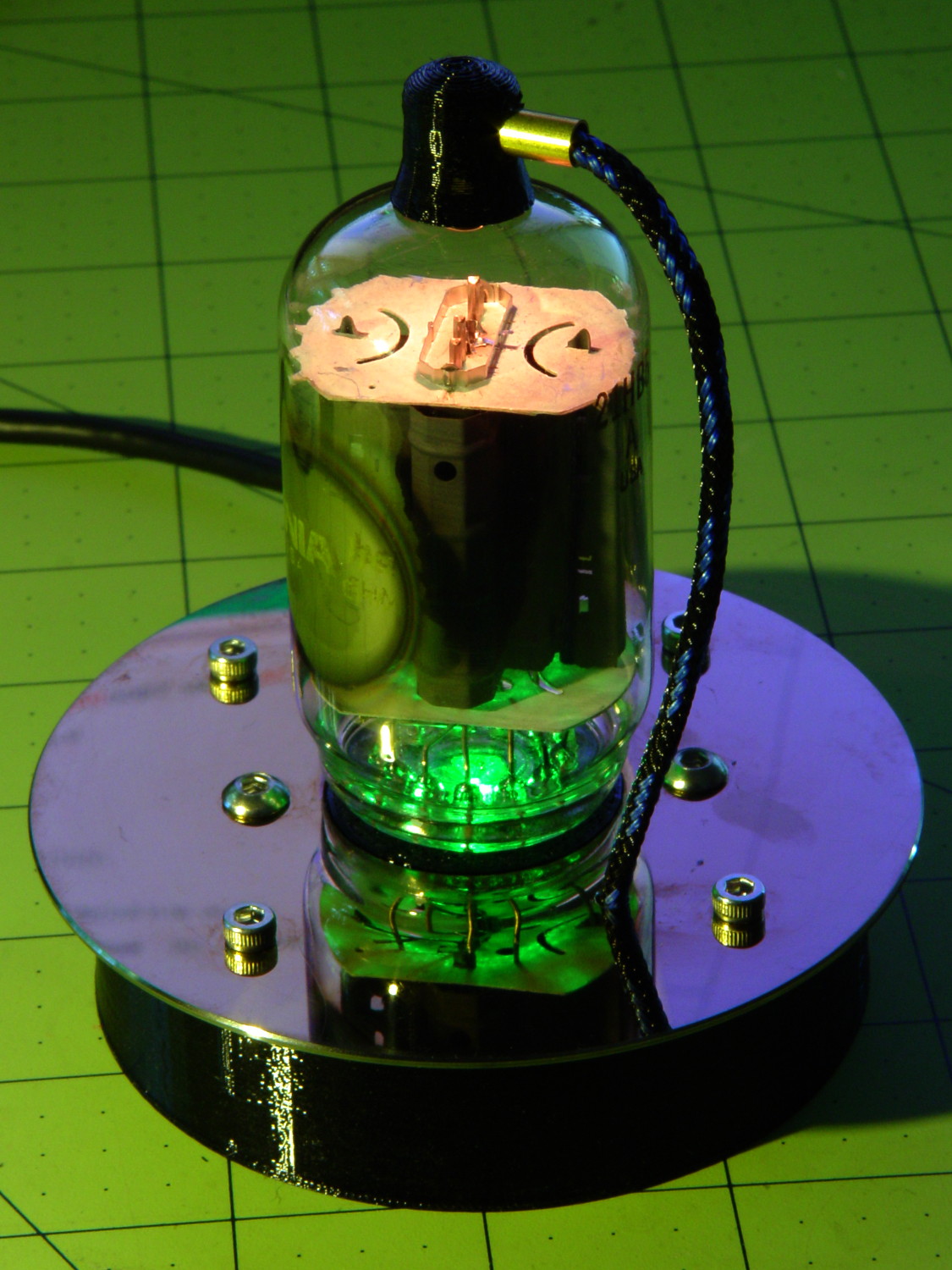
The 5U4GB side lighted dual rectifier looks pretty good after I increased the phase between the two LEDs:

A gaggle of glowing vacuum tubes makes for a rather static display, though, so I conjured a color mixer so folks could play with the colors:
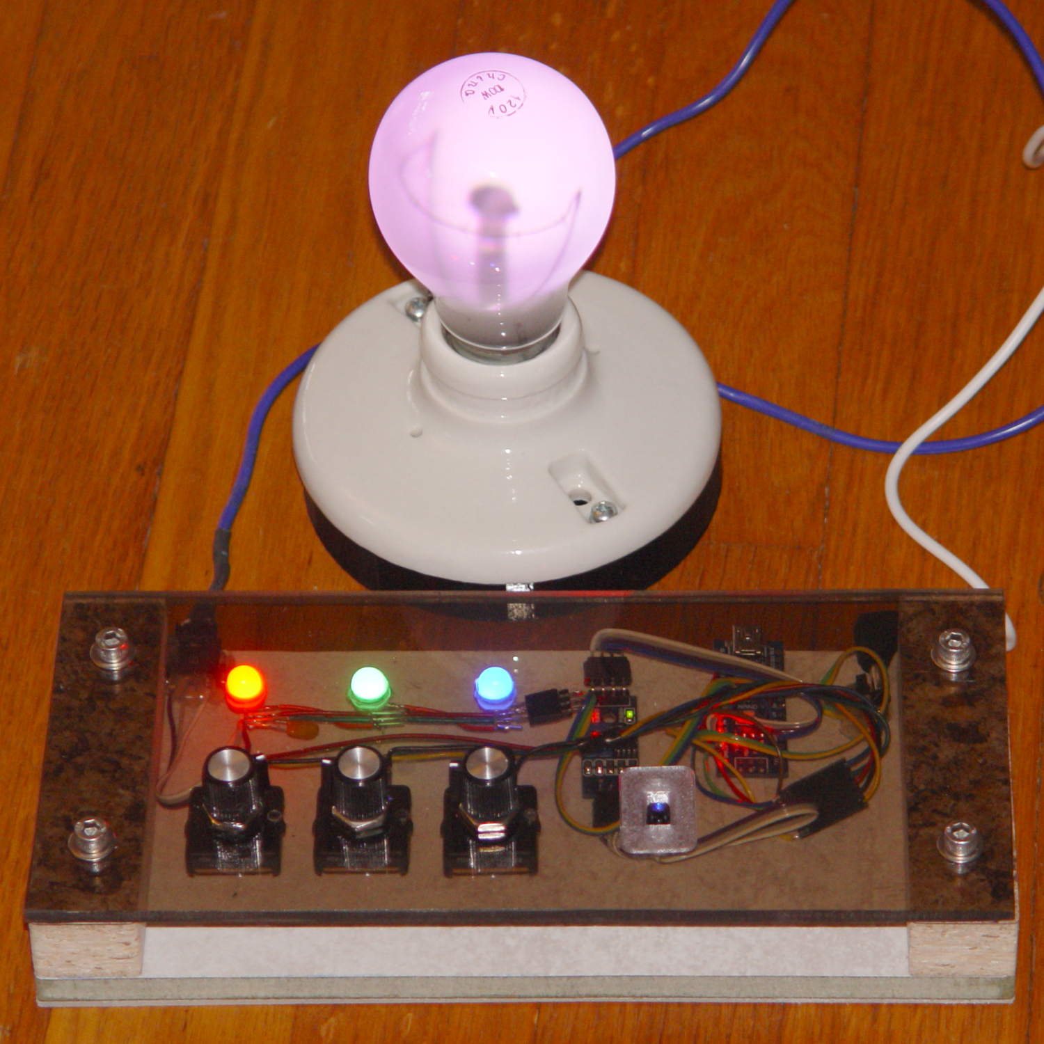
Three analog potentiometers set the intensity of the pure RGB colors on the 8 mm Genuine Adafruit Neopixels. A closer look at the circuitry shows it’s assembled following a freehand “the bigger the blob, the better the job” soldering technique:
The blended RGB color from a fourth Neopixel backlights the bulb to project a shadow of the filament on the front surface:

It’s worth noting that the three Genuine Adafruit 8 mm Neopixels have a nonstandard RGB color layout, while the knockoff 5050 SMD Neopixel on the bulb has the usual GRB layout. You can’t mix-n-match layouts in a single Neopixel string, so a few lines of hackage rearrange the R and G values to make the mixed colors come out right.
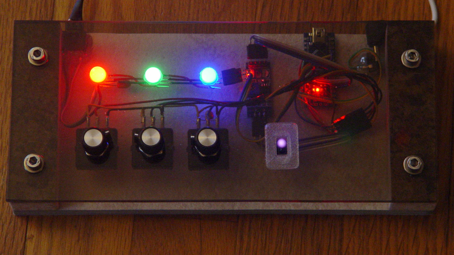
An IR proximity sensor lets you invert the colors with the wave of a fingertip to send Morse code in response to (some of) the vacuum tubes on display nearby. The sensor glows brightly in pure IR, with all the other LEDs going dark:
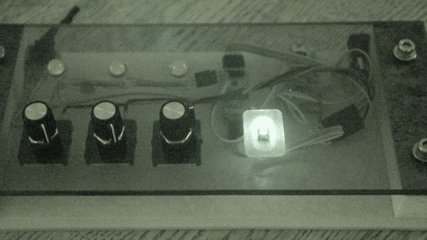
The switch sits in a little printed bezel to make it big enough to see. The slight purple glow in the visible-light picture comes from the camera’s IR sensitivity; you can’t see anything with your (well, my) unaided eyes.
The “chassis” emerged from the wood pile: a slab of laminate flooring and two strips of countertop, with a slab of bronze-tint acrylic from a Genuine IBM PC Printer Stand that had fallen on hard times quite a while ago. Bandsaw to size, belt-sand to smooth; nothing particularly precise, although I did use the Sherline for coordinate drilling:

That’s laying it all out by hand to get a feel for what it’ll look like and drilling the holes at actual coordinates to make everything line up neatly.
Hot melt glue and epoxy hold everything together, with foam tape securing the two PCBs. Those cap screws go into 10-32 brass inserts hammered into the laminate flooring strip.
There’s no schematic. Connect the pots to A0 through A2, wire the Neopixels in series from D8 with the bulb LED last in the string, wire the prox sensor to D9, and away you go.
It’s fun to play with colors!
The Arduino source code as a GitHub Gist:
| // Color mixing demo for Mini Maker Faire | |
| // Ed Nisley – KE4ANU – November 2016 | |
| #include <Adafruit_NeoPixel.h> | |
| //———- | |
| // Pin assignments | |
| #define PIN_NEO 8 // DO – data out to first Neopixel | |
| #define PIN_HEARTBEAT 13 // DO – Arduino LED | |
| #define PIN_FLASH 9 // DI – flash button | |
| #define PIN_POTRED A0 // AI – red potentiometer | |
| #define PIN_POTGREEN A1 // AI – green potentiometer | |
| #define PIN_POTBLUE A2 // AI – blue potentiometer | |
| //———- | |
| // Constants | |
| #define PIXELS 4 // number of pixels | |
| #define PIXEL_RED 2 // physical channel layout | |
| #define PIXEL_GREEN 1 | |
| #define PIXEL_BLUE 0 | |
| #define PIXEL_MIX (PIXELS – 1) // pixel with mixed color | |
| #define PIXEL_FLASH (PIXELS – 1) // pixel that flashes | |
| // update LEDs only this many ms apart (minus loop() overhead) | |
| #define UPDATEINTERVAL 25ul | |
| #define UPDATEMS (UPDATEINTERVAL – 1ul) | |
| //———- | |
| // Globals | |
| // instantiate the Neopixel buffer array | |
| // color order is RGB for 8 mm diffuse LEDs, GRB for mixed 5050 LED at end | |
| Adafruit_NeoPixel strip = Adafruit_NeoPixel(PIXELS, PIN_NEO, NEO_RGB + NEO_KHZ800); | |
| uint32_t FullWhite = strip.Color(255,255,255); | |
| uint32_t FullOff = strip.Color(0,0,0); | |
| // colors in each LED | |
| enum pixcolors {RED, GREEN, BLUE, PIXELSIZE}; | |
| uint32_t PotColors[PIXELSIZE]; | |
| uint32_t UniColor; | |
| unsigned long MillisNow; | |
| unsigned long MillisThen; | |
| //– Helper routine for printf() | |
| int s_putc(char c, FILE *t) { | |
| Serial.write(c); | |
| } | |
| //—————— | |
| // Set the mood | |
| void setup() { | |
| pinMode(PIN_HEARTBEAT,OUTPUT); | |
| digitalWrite(PIN_HEARTBEAT,LOW); // show we arrived | |
| Serial.begin(57600); | |
| fdevopen(&s_putc,0); // set up serial output for printf() | |
| printf("Color Mixer Demo for Mini Maker Faire\r\nEd Nisley – KE4ZNU – November 2016\r\n"); | |
| // set up pixels | |
| strip.begin(); | |
| strip.show(); | |
| // lamp test: a brilliant white flash on all pixels | |
| // pixel color layout doesn't matter for a white flash | |
| printf("Lamp test: flash white\r\n"); | |
| for (byte i=0; i<5 ; i++) { | |
| for (int j=0; j < strip.numPixels(); j++) { // fill LEDs with white | |
| strip.setPixelColor(j,FullWhite); | |
| } | |
| strip.show(); | |
| delay(500); | |
| for (int j=0; j < strip.numPixels(); j++) { // fill LEDs with black | |
| strip.setPixelColor(j,FullOff); | |
| } | |
| strip.show(); | |
| delay(500); | |
| } | |
| // lamp test: walk a white flash along the string | |
| printf("Lamp test: walking white\r\n"); | |
| strip.setPixelColor(0,FullWhite); | |
| strip.show(); | |
| delay(500); | |
| for (int i=1; i<strip.numPixels(); i++) { | |
| digitalWrite(PIN_HEARTBEAT,HIGH); | |
| strip.setPixelColor(i-1,FullOff); | |
| strip.setPixelColor(i,FullWhite); | |
| strip.show(); | |
| digitalWrite(PIN_HEARTBEAT,LOW); | |
| delay(500); | |
| } | |
| strip.setPixelColor(strip.numPixels() – 1,FullOff); | |
| strip.show(); | |
| delay(500); | |
| MillisNow = MillisThen = millis(); | |
| } | |
| //—————— | |
| // Run the mood | |
| void loop() { | |
| MillisNow = millis(); | |
| if ((MillisNow – MillisThen) >= UPDATEMS) { // time for color change? | |
| digitalWrite(PIN_HEARTBEAT,HIGH); | |
| PotColors[RED] = strip.Color(analogRead(PIN_POTRED) >> 2,0,0); | |
| PotColors[GREEN] = strip.Color(0,analogRead(PIN_POTGREEN) >> 2,0); | |
| PotColors[BLUE] = strip.Color(0,0,analogRead(PIN_POTBLUE) >> 2); | |
| strip.setPixelColor(PIXEL_RED,PotColors[RED]); // load up pot indicators | |
| strip.setPixelColor(PIXEL_GREEN,PotColors[GREEN]); | |
| strip.setPixelColor(PIXEL_BLUE,PotColors[BLUE]); | |
| strip.setPixelColor(PIXEL_MIX,strip.getPixelColor(PIXEL_RED) | | |
| strip.getPixelColor(PIXEL_GREEN) | | |
| strip.getPixelColor(PIXEL_BLUE)); | |
| if (PIXEL_FLASH != PIXEL_MIX) { | |
| strip.setPixelColor(PIXEL_FLASH,strip.getPixelColor(PIXEL_MIX)); | |
| } | |
| if (LOW == digitalRead(PIN_FLASH)) { // if flash input active, overlay flash | |
| strip.setPixelColor(PIXEL_FLASH,0x00FFFFFF ^ strip.getPixelColor(PIXEL_FLASH)); | |
| strip.setPixelColor(PIXEL_RED, 0x00FF0000 ^ strip.getPixelColor(PIXEL_RED)); | |
| strip.setPixelColor(PIXEL_GREEN,0x0000FF00 ^ strip.getPixelColor(PIXEL_GREEN)); | |
| strip.setPixelColor(PIXEL_BLUE, 0x000000FF ^ strip.getPixelColor(PIXEL_BLUE)); | |
| } | |
| UniColor = 0x000000ff & strip.getPixelColor(PIXELS – 1); // hack to rearrange colors for 5050 LED | |
| UniColor |= 0x00ff0000 & (strip.getPixelColor(PIXELS – 1) << 8); | |
| UniColor |= 0x0000ff00 & (strip.getPixelColor(PIXELS – 1) >> 8); | |
| strip.setPixelColor(PIXELS – 1,UniColor); | |
| strip.show(); // send out colors | |
| MillisThen = MillisNow; | |
| digitalWrite(PIN_HEARTBEAT,LOW); | |
| } | |
| } |

Comments
4 responses to “Vacuum Tube Lights: Poughkeepsie Day School Mini Maker Faire 2016”
Completely off topic, but do you have any info on the Elitech RC-5 temperature dataloggers? I could use a few for temp only, and the HOBOs are considerably more expensive.(Elitech runs $20 each, and the HOBOs seem to run $100 unless I’m missing something.) From what I’ve seen puzzling out the Amazon reviews, the hardware seems OK, but the Windows software ranges from OK-ish to Gawdawful, depending on who sells it. (I’d consider the Python loader on a Linux box, so that should be moot.
I know nozzink, but they certainly look interesting. On a casual look, I can’t find the Python driver; what’s the right set of search parameters?
Update: found it! https://pypi.python.org/pypi/elitech-datareader/0.9.4
The current crop of HOBO sensors seem to be overkill (waterproof, with optical I/O so you can read a dripping wet sensor) or tiny in memory, or integrated with a fancy display. I have an immediate need for one or two, and a few more could be useful. I could use -30C, and the less expensive modules get that with some fuzziness in accuracy below -20C.
This is in support for my just-finished “summer” project (got derailed a bit with the kitchen fiasco), a 1.6kW solar/3.6kW inverter power trailer. It’ll give backup power for us if/when we lose mains. The system is based on an Outback Power module that would like to see a min temp of 55F, and a 110V thermostat running a lightbulb should keep the insulated cabinet warm. The batteries have their own unheated insulated box, and Outback has a battery temp sensor to control those. The control module is pretty sophisticated, but ambient temperature doesn’t seem to be measured. (They have it set up so you can let it talk to The Cloud, but I don’t want to deal with the Botnet of Things.)
I plan to use the same type of system (less trailer) for our new well, so using a datalogger that’s reasonably standard and reasonably affordable makes sense. The pumphouse will be well insulated and heated, and I want to verify that…
Time for another Amazon order, and time to pull the trigger on the off-lease Dell laptop.
[…] a few TCRT5000 proximity sensors lying around, I used one for the Color Mixer so folks could just wave a finger to flip the LED colors, rather than pound relentlessly on the top […]