The Smell of Molten Projects in the Morning

Ed Nisley's Blog: Shop notes, electronics, firmware, machinery, 3D printing, laser cuttery, and curiosities. Contents: 100% human thinking, 0% AI slop.

Tag: M2

Using and tweaking a Makergear M2 3D printer

  • Step2 Garden Seat: Replacement Seat

    Step2 Garden Seat: Replacement Seat

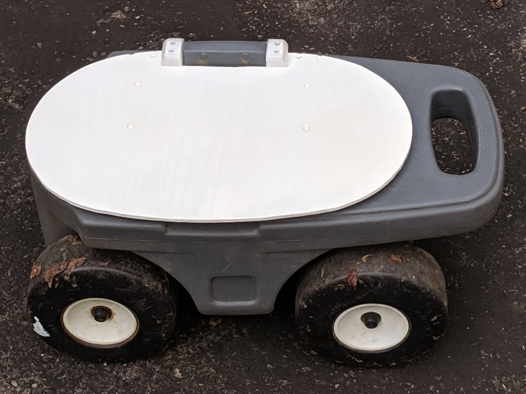
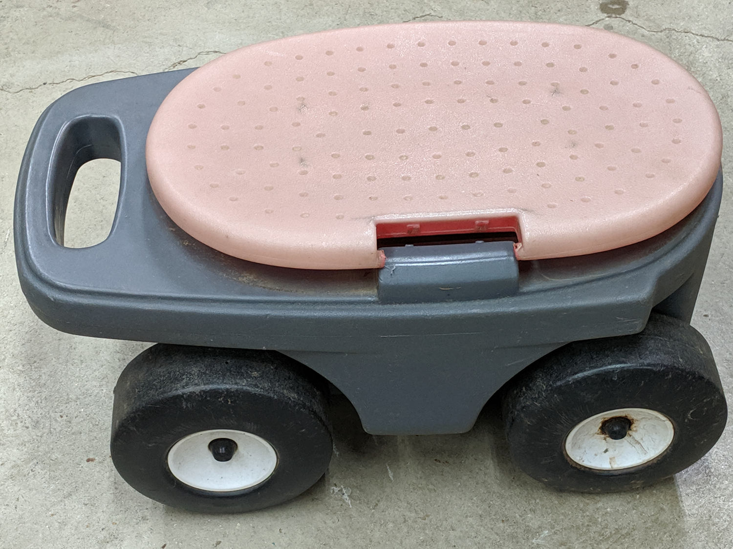
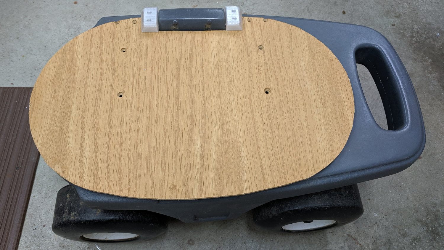
    A pair of Step2 rolling garden seats (they have a new version) served in Mary’s gardens long enough to give their seat panels precarious cracks:

    Step2 Seat - OEM seat
    Step2 Seat – OEM seat

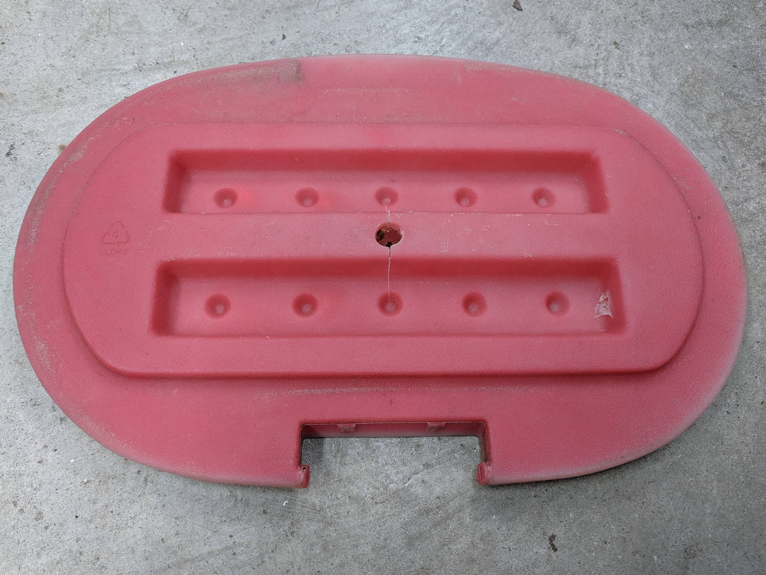
    The underside was giving way, too:

    Step2 Seat - cracks
    Step2 Seat – cracks

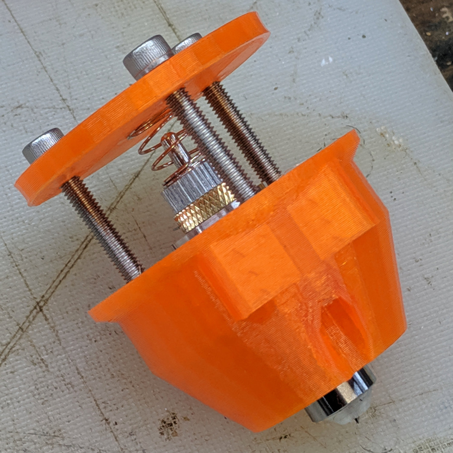
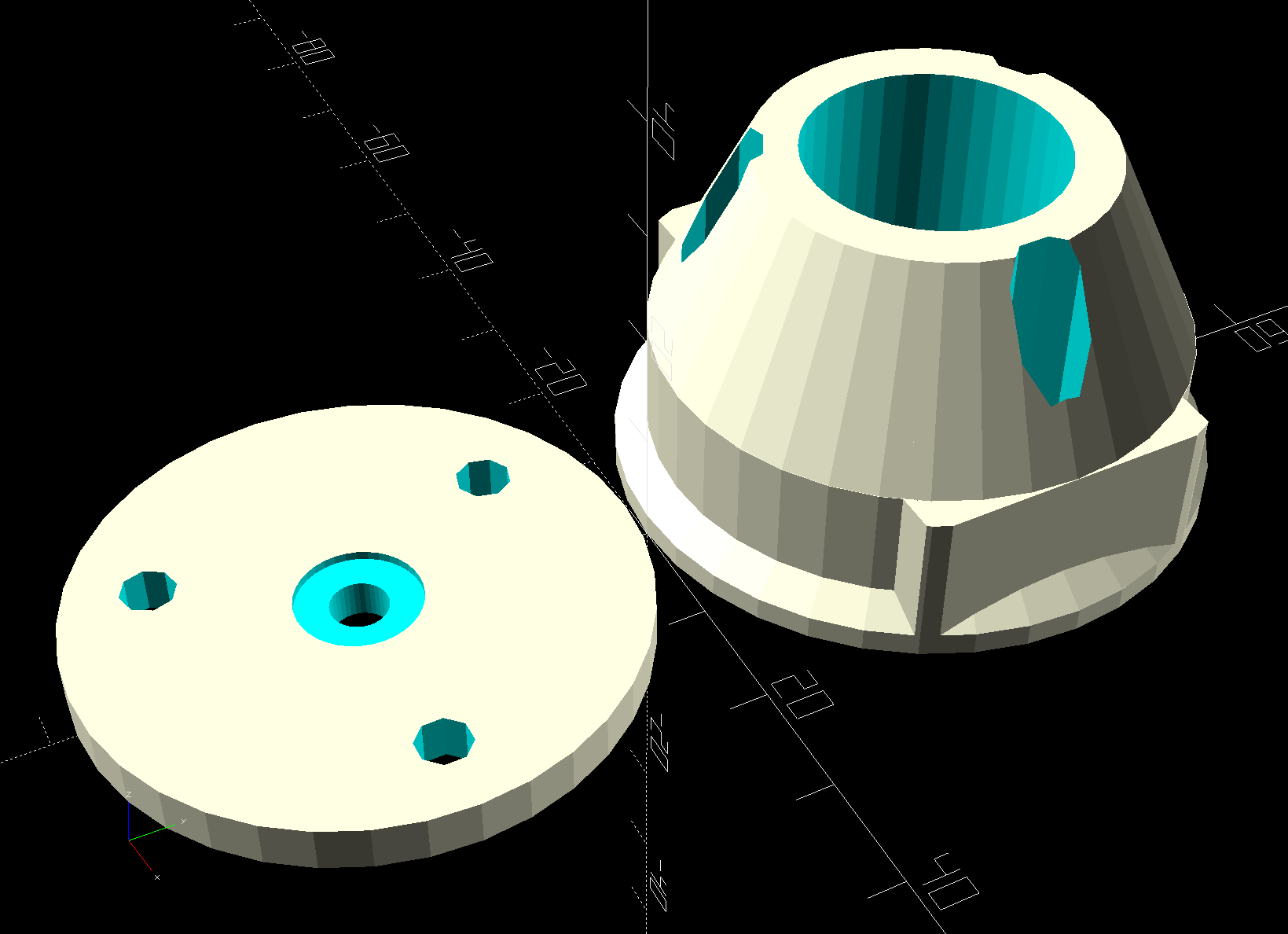
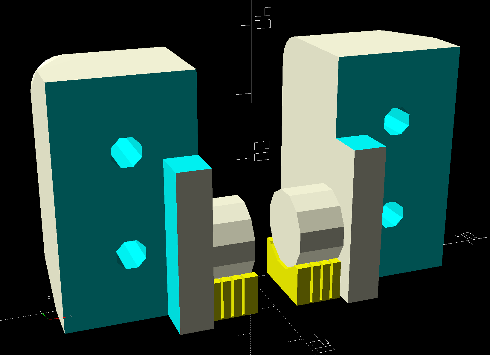
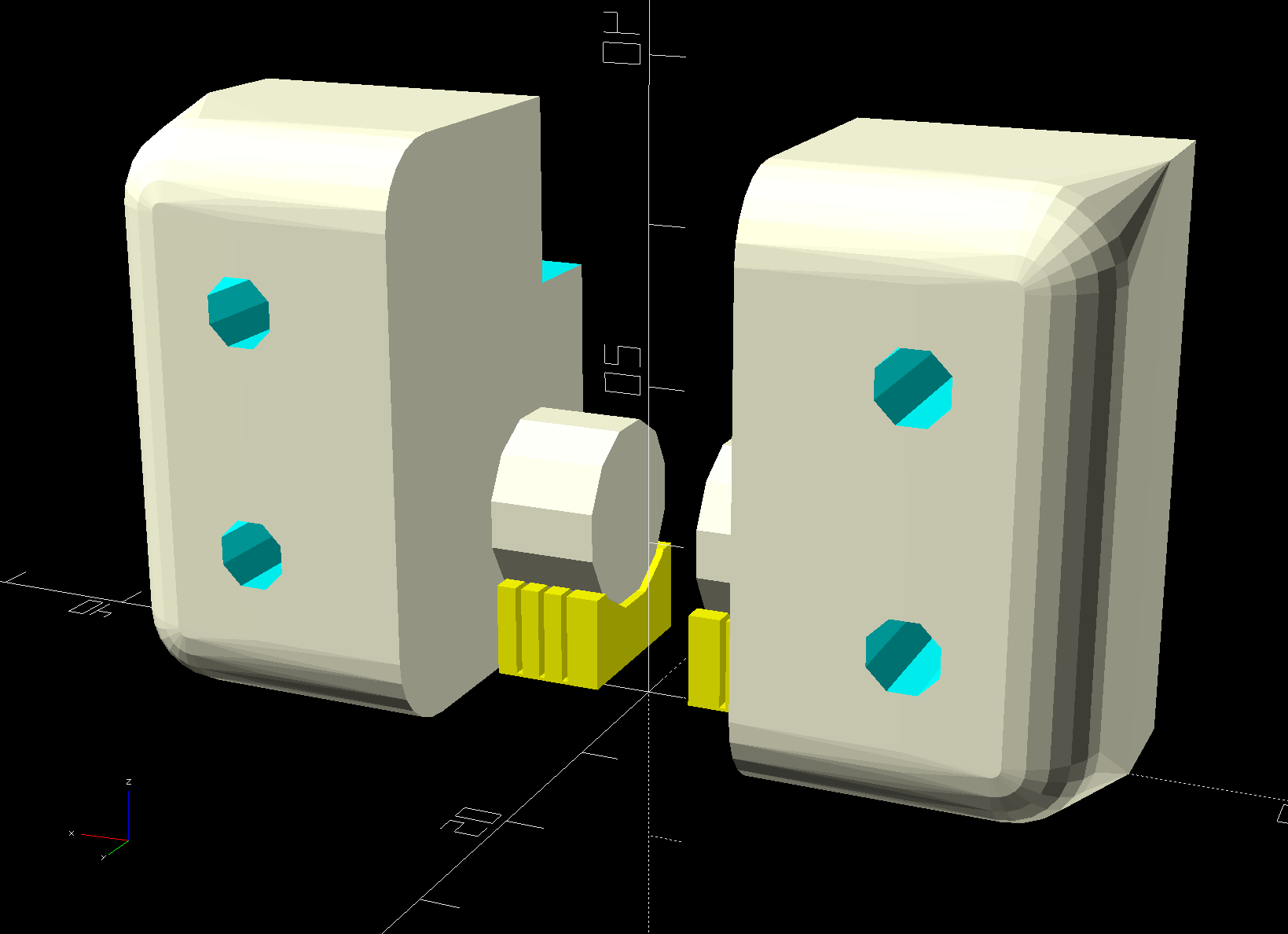
    We agreed the new seat could be much simpler, although it must still hinge upward, so I conjured a pair of hinges from the vasty digital deep:

    Rolling Cart Hinges - solid model - bottom
    Rolling Cart Hinges – solid model – bottom

    The woodpile disgorged a slab of 1/4 inch = 6 mm plywood (used in a defunct project) of just about the right size and we agreed a few holes wouldn’t be a problem for its projected ahem use case:

    Step2 Seat - assembled
    Step2 Seat – assembled

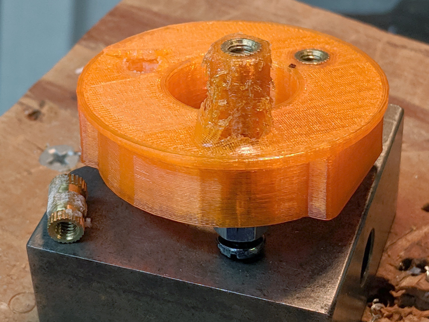
    The screw holes on the hinge tops will let me run machine screws all the way through, should that be necessary. So far, a quartet of self-tapping sheet metal (!) screws are holding firm.

    Rolling Cart Hinges - solid model - top
    Rolling Cart Hinges – solid model – top

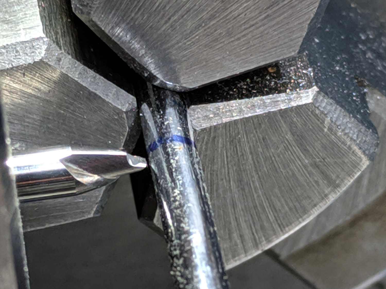
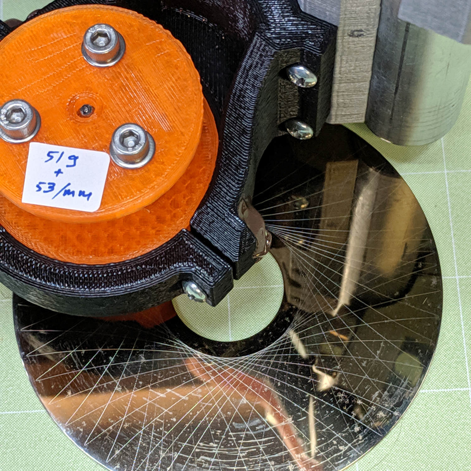
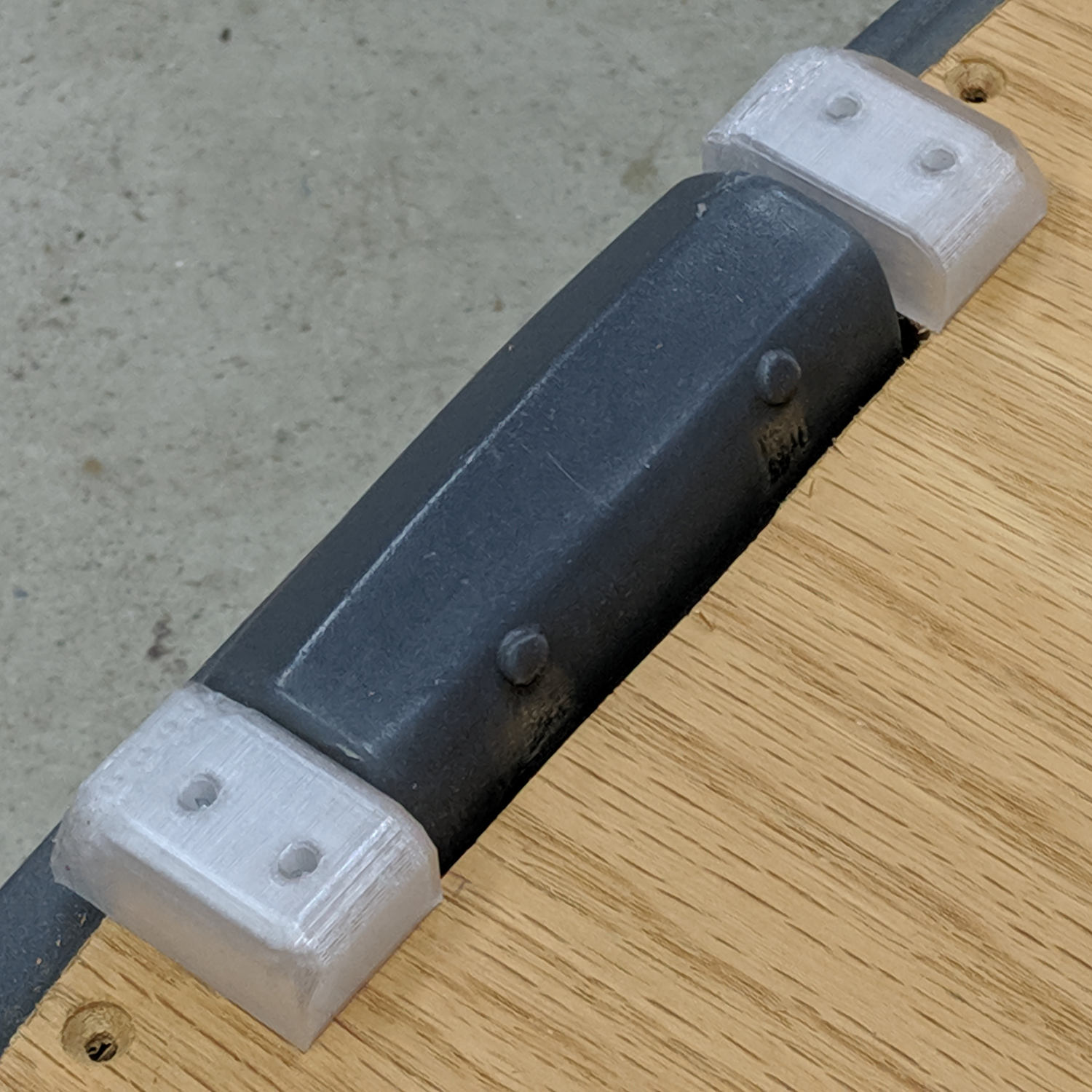
    A closer look at the hinges in real life:

    Step2 Seat - top view
    Step2 Seat – top view

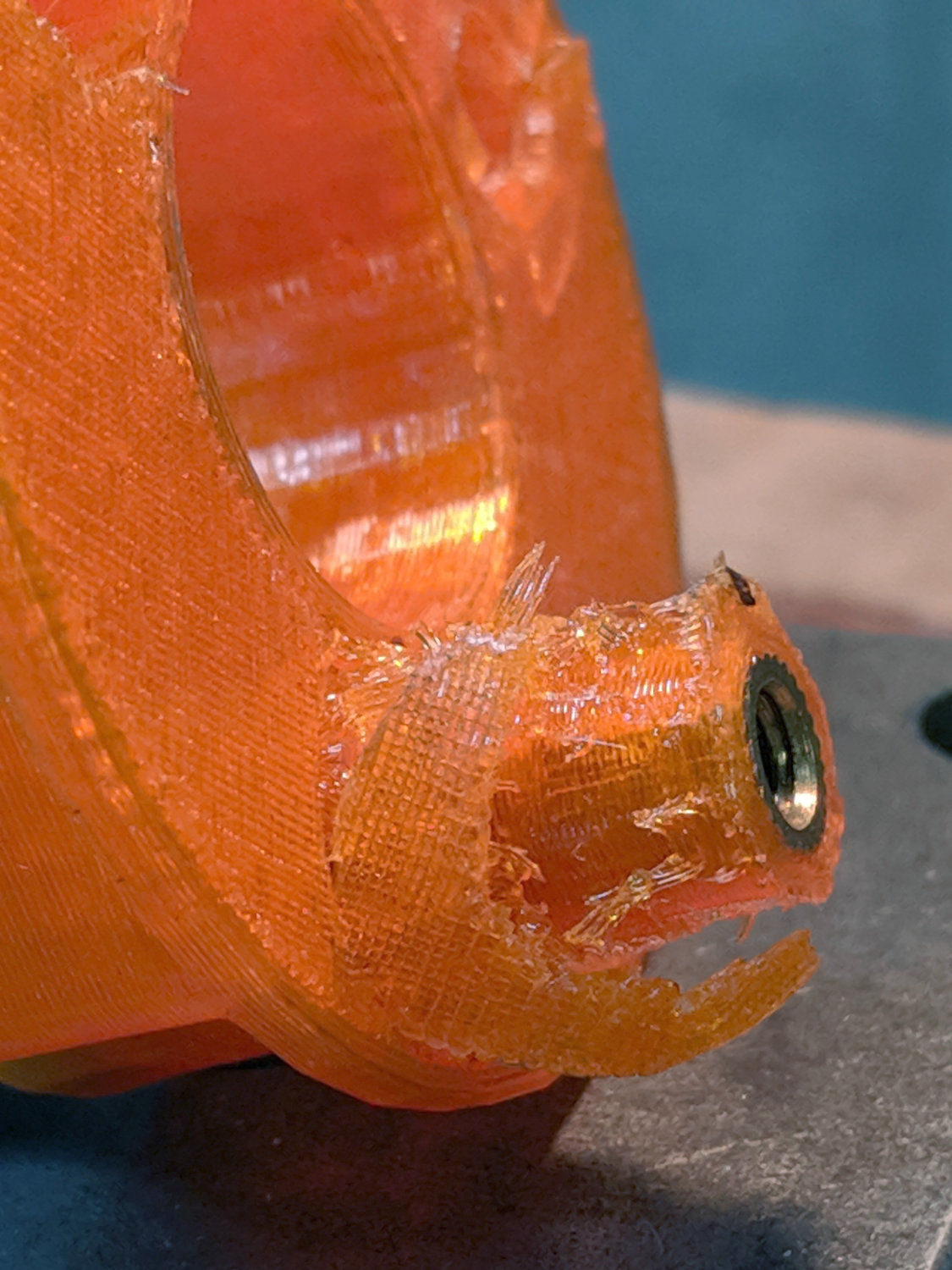
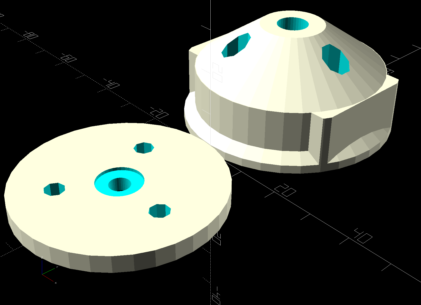
    The solid model now caps the holes; I can drill them out should the need arise.

    From the bottom:

    Step2 Seat - bottom view
    Step2 Seat – bottom view

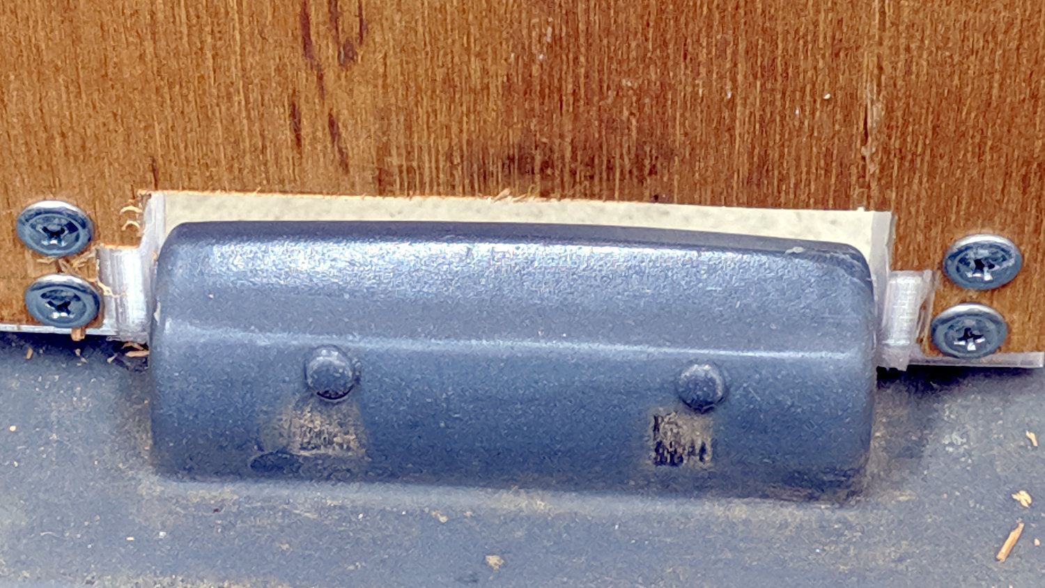
    Three coats of white exterior paint make it blindingly bright in the sun, although we expect a week or two in the garden will knock the shine right off:

    Step2 Seat - painted
    Step2 Seat – painted

    After the first coat, I conjured a drying rack from a bamboo skewer, a cardboard flap, and some hot-melt glue:

    Step2 Seat - drying fixture
    Step2 Seat – drying fixture

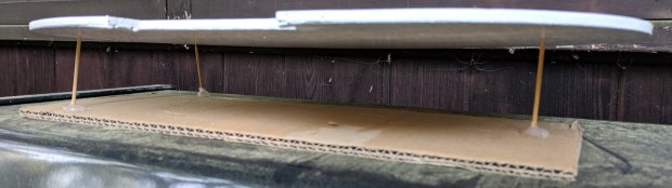
    Three small scars on the seat bottom were deemed acceptable.

    The OpenSCAD source code as a GitHub Gist:

    // Hinge brackets for rolling garden stool
    // Ed Nisley – KE4ZNU – 2019-06
    Layout = "Build"; // [Block,Build,Show]
    Support = true;
    /* [Hidden] */
    ThreadThick = 0.20;
    ThreadWidth = 0.40;
    HoleWindage = 0.2;
    Protrusion = 0.1; // make holes end cleanly
    ID = 0;
    OD = 1;
    LENGTH = 2;
    //———————-
    // Dimensions
    SeatThick = 6.0; // seat panel above cart body
    HingePin = [11.5,12.0,7.0]; // ID = tip OD = base
    HingeOffset = 8.0; // hinge axis above cart body (larger than radius!)
    HingeBolster = [5.0,24.0,SeatThick]; // backing block below hinge
    Block = [25.0,HingeOffset + 30.0,23.0]; // Z = above cart body
    Screw = [3.8,11.0,2.5]; // self-tapping #8 OD=head LENGTH=head thickness
    ScrewOC = 15.0; // spacing > greater than head OD
    ScrewOffset = Block.y/2 – (ScrewOC/2 + Screw[OD]/2 + HingeOffset); // space for head behind hinge
    BlockRadius = 7.0; // corner rounding
    //———————-
    // Useful routines
    module PolyCyl(Dia,Height,ForceSides=0) { // based on nophead's polyholes
    Sides = (ForceSides != 0) ? ForceSides : (ceil(Dia) + 2);
    FixDia = Dia / cos(180/Sides);
    cylinder(r=(FixDia + HoleWindage)/2,
    h=Height,
    $fn=Sides);
    }
    // Basic block shape
    // X axis collinear with hinge axes, hinge base at X=0
    module HingeBlock() {
    PinSides = 3*4;
    PinSupport = [HingePin[LENGTH] – 2*ThreadWidth,0.6*HingeOffset,HingePin[OD]]; // pre-rotated
    union() {
    translate([Protrusion,Block.y/2 – HingeOffset,HingeOffset])
    rotate([0,-90,0])
    rotate(180/PinSides)
    cylinder(d=HingePin[OD],h=HingePin[LENGTH] + Protrusion,$fn=PinSides);
    difference() {
    hull() {
    translate([Block.x – BlockRadius,-(Block.y/2 – BlockRadius),Block.z – BlockRadius])
    rotate(180/PinSides)
    sphere(r=BlockRadius/cos(180/PinSides),$fn=PinSides);
    translate([0,-(Block.y/2 – BlockRadius),Block.z – BlockRadius])
    rotate([0,90,0]) rotate(180/PinSides)
    cylinder(r=BlockRadius/cos(180/PinSides),h=Block.x/2,$fn=PinSides);
    translate([Block.x – BlockRadius,(Block.y/2 – BlockRadius),Block.z – BlockRadius])
    sphere(r=BlockRadius/cos(180/PinSides),$fn=PinSides);
    translate([0,(Block.y/2 – BlockRadius),Block.z – BlockRadius])
    rotate([0,90,0]) rotate(180/PinSides)
    cylinder(r=BlockRadius/cos(180/PinSides),h=Block.x/2,$fn=PinSides);
    translate([0,-Block.y/2,0])
    cube([Block.x,Block.y – HingeOffset,Block.z/2],center=false);
    translate([0,Block.y/2 – HingeOffset,HingeOffset])
    rotate([0,90,0]) rotate(180/PinSides)
    cylinder(r=HingeOffset/cos(180/PinSides),h=Block.x,$fn=PinSides);
    }
    translate([Block.x/2 + HingeBolster.x,0,(SeatThick – Protrusion)/2])
    cube([Block.x,2*Block.y,SeatThick + Protrusion],center=true);
    translate([0,-HingeBolster.y,(SeatThick – Protrusion)/2])
    cube([3*Block.x,Block.y,SeatThick + Protrusion],center=true);
    for (j=[-1,1])
    translate([Block.x/2,j*ScrewOC/2 + ScrewOffset,-4*ThreadThick])
    rotate(180/8)
    PolyCyl(Screw[ID],Block.z,8);
    }
    }
    if (Support) { // totally ad-hoc
    color("Yellow") render(convexity=4)
    difference() {
    translate([-(PinSupport.x/2 + 2*ThreadWidth),Block.y/2 – PinSupport.y/2,HingeOffset])
    cube(PinSupport,center=true);
    translate([Protrusion,Block.y/2 – HingeOffset,HingeOffset])
    rotate([0,-90,0])
    rotate(180/PinSides)
    cylinder(d=HingePin[OD] + 2*ThreadThick,h=2*HingePin[LENGTH],$fn=PinSides);
    for (i=[-1:1])
    translate([i*4*ThreadWidth – HingePin[LENGTH]/2,
    Block.y/2 – (PinSupport.y + 1*ThreadThick),
    HingeOffset])
    cube([2*ThreadWidth,2*PinSupport.y,2*PinSupport.z],center=true);
    }
    }
    }
    module Blocks(Hand = "Left") {
    if (Hand == "Left")
    HingeBlock();
    else
    mirror([1,0,0])
    HingeBlock();
    }
    //- Build it
    if (Layout == "Block")
    HingeBlock();
    if (Layout == "Show") {
    translate([1.5*HingePin[LENGTH],0,0])
    Blocks("Left");
    translate([-1.5*HingePin[LENGTH],0,0])
    Blocks("Right");
    }
    if (Layout == "Build") {
    translate([0,-Block.z/2,Block.y/2])
    rotate([-90,0,0]) {
    translate([1.5*HingePin[LENGTH],0,0])
    Blocks("Left");
    translate([-1.5*HingePin[LENGTH],0,0])
    Blocks("Right");
    }
    }

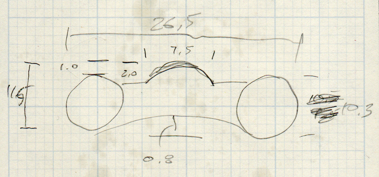
    This original doodle gives the key dimensions, apart from the rounded rear edge required so the seat can pivot vertically upward:

    Cart Hinge - dimension doodle
    Cart Hinge – dimension doodle

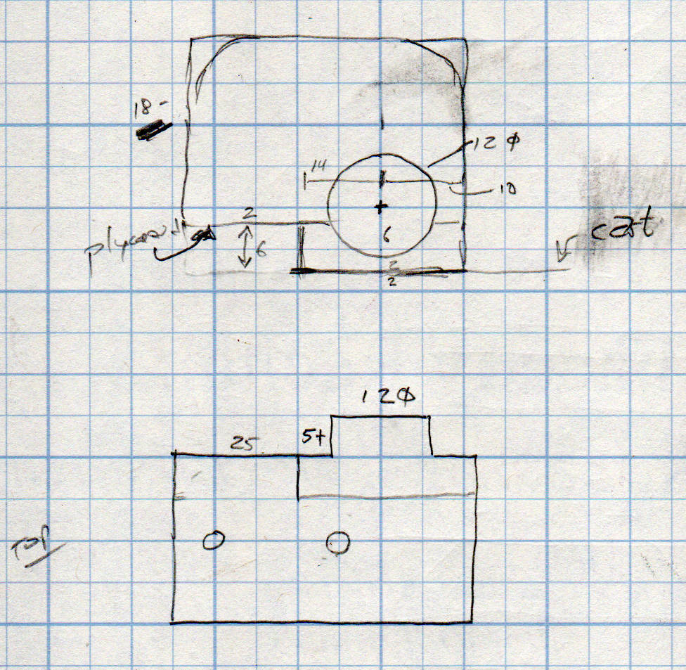
    The second seat looks just like this one, so life is good …

  • Drag Knife Blade Ejector Handle

    The LM12UU drag knife holder buries the blade ejector pin deep inside the machinery:

    Drag Knife - LM12UU ground shaft - assembled
    Drag Knife – LM12UU ground shaft – assembled

    So a handle with a pin makes sense:

    LM12UU Drag Knife Ejector Pin Pusher
    LM12UU Drag Knife Ejector Pin Pusher

    It’s a variant Sherline tommy bar handle, so there’s not much to say about it.

    The dark butt end comes from the traces of the black filament I used for the previous part. Even after flushing half a meter of orange through the hot end, you’ll still see some contamination, even with the same type of plastic. Doesn’t make much difference here, though.

  • Threaded Brass Inserts: Test to Destruction

    With an outmoded LM12UU linear bearing drag knife mount on hand, I threaded an M4 screw into each brass insert, lined it up on a hole in a homebrew (by a long-gone machinist, not me) steel bench block, and applied pressure with the drill press until the insert tore out:

    Brass Insert Retention test - A B
    Brass Insert Retention test – A B

    The retina-burn orange ring is printed in PETG with my usual slicer settings: three perimeter threads, three top and bottom layers, and 15% 3D honeycomb infill. That combination is strong enough and stiff enough for essentially everything I do around here.

    The insert on the left came out of its hole carrying its layer of epoxy: the epoxy-to-hole bond failed first. Despite that, punching it out required enough force to convince me it wasn’t going anywhere on its own.

    The column of plastic around the insert standing up from the top fits into the central hole (hidden in the picture) in the bench block. Basically, the edge of the hole applied enough shear force to the plastic to break the infill before the epoxy tore free, with me applying enough grunt to the drill press quill handle to suggest I should get a real arbor press if I’m going to keep doing this.

    The third insert maintained a similar grip, as seen from the left:

    Brass Insert Retention test - C left
    Brass Insert Retention test – C left

    And the right:

    Brass Insert Retention test - C right
    Brass Insert Retention test – C right

    The perimeter threads around the hole tore away from the infill, with the surface shearing as the plastic column punched through.

    Bottom line: a dab of epoxy anchors an insert far better than the 3D printed structure around it can support!

  • MPCNC Collet Pen Holder: LM12UU Edition

    Encouraged by the smooth running of the LM12UU drag knife mount, I chopped off another length of 12 mm shaft:

    LM12UU Collet Pen Holder - sawing shaft
    LM12UU Collet Pen Holder – sawing shaft

    The MicroMark Cut-off saw was barely up to the task; I must do something about its craptastic “vise”. In any event, the wet rags kept the shaft plenty cool and the ShopVac hose directly behind the motor sucked away all of the flying grit.

    The reason I used an abrasive wheel: the shaft is case-hardened and the outer millimeter or two is hard enough to repel a carbide cutter:

    LM12UU Collet Pen Holder - drilling shaft
    LM12UU Collet Pen Holder – drilling shaft

    Fortunately, the middle remains soft enough to drill a hole for the collet pen holder, which I turned down to a uniform 8 mm (-ish) diameter:

    LM12UU Collet Pen Holder - turning collet body
    LM12UU Collet Pen Holder – turning collet body

    Slather JB Kwik epoxy along the threads, insert into the shaft, wipe off the excess, and it almost looks like a Real Product:

    LM12UU Collet Pen Holder - finished body
    LM12UU Collet Pen Holder – finished body

    The far end of the shaft recesses the collet a few millimeters to retain the spring around the pen body, which will also require a knurled ring around the outside so you (well, I) can tighten the collet around the pen tip.

    Start the ring by center-drilling an absurdly long aluminum rod in the steady rest:

    M12UU Collet Pen Holder - center drilling
    M12UU Collet Pen Holder – center drilling

    Although it’s not obvious, I cleaned up the OD before applying the knurling tool:

    LM12UU Collet Pen Holder - knurling
    LM12UU Collet Pen Holder – knurling

    For some unknown reason, it seemed like a Good Idea to knurl without the steady rest, perhaps to avoid deepening the ring where the jaws slide, but Tiny Lathe™ definitely wasn’t up to the challenge. The knurling wheels aren’t quite concentric on their bores and their shafts have plenty of play, so I got to watch the big live center and tailstock wobbulate as the rod turned.

    With the steady rest back in place, drill out the rod to match the shaft’s 12 mm OD:

    LM12UU Collet Pen Holder - drilling shaft
    LM12UU Collet Pen Holder – drilling shaft

    All my “metric” drilling uses hard-inch drills approximating the metric dimensions, of course, because USA.

    Clean up the ring face, file a chamfer on the edge, and part it off:

    LM12UU Collet Pen Holder - parting ring
    LM12UU Collet Pen Holder – parting ring

    Turn some PVC pipe to a suitable length, slit one side so it can collapse to match the ring OD, wrap shimstock to protect those lovely knurls, and face off all the ugly:

    LM12UU Collet Pen Holder - knurled ring facing
    LM12UU Collet Pen Holder – knurled ring facing

    Tweak the drag knife’s solid model for a different spring from the collection and up the hole OD in the plate to clear the largest pen cartridge in the current collection:

    Collet Holder - LM12UU - solid model
    Collet Holder – LM12UU – solid model

    Convince all the parts to fly in formation, then measure the spring rate:

    LM12UU Collet Pen Holder - spring rate test
    LM12UU Collet Pen Holder – spring rate test

    Which works out to be 128 g + 54 g/mm:

    LM12UU Collet Pen Holder - test plot - overview
    LM12UU Collet Pen Holder – test plot – overview

    I forgot the knurled ring must clear the screws and, ideally, the nyloc nuts. Which it does, after I carefully aligned each nut with a flat exactly tangent to the ring. Whew!

    A closer look at the business end:

    LM12UU Collet Pen Holder - test plot - detail
    LM12UU Collet Pen Holder – test plot – detail

    The shaft has 5 mm of travel, far more than enough for the MPCNC’s platform. Plotting at -1 mm applies 180 g of downforce; the test pattern shown above varies the depth from 0.0 mm in steps of -0.1 mm; anything beyond -0.2 mm gets plenty of ink.

    Now I have a pen holder, a diamond scribe, and a drag knife with (almost) exactly the same “tool offset” from the alignment camera, thereby eliminating an opportunity to screw up.

    The OpenSCAD source code as a GitHub Gist:

    // Collet pen cartridge holder using LM12UU linear bearing
    // Ed Nisley KE4ZNU – 2019-04-26
    // 2019-06 Adapted from LM12UU drag knife holder
    Layout = "Build"; // [Build, Show, Puck, Mount, Plate]
    /* [Extrusion] */
    ThreadThick = 0.25; // [0.20, 0.25]
    ThreadWidth = 0.40; // [0.40]
    /* [Hidden] */
    Protrusion = 0.1; // [0.01, 0.1]
    HoleWindage = 0.2;
    inch = 25.4;
    function IntegerMultiple(Size,Unit) = Unit * ceil(Size / Unit);
    ID = 0;
    OD = 1;
    LENGTH = 2;
    //- Adjust hole diameter to make the size come out right
    module PolyCyl(Dia,Height,ForceSides=0) { // based on nophead's polyholes
    Sides = (ForceSides != 0) ? ForceSides : (ceil(Dia) + 2);
    FixDia = Dia / cos(180/Sides);
    cylinder(r=(FixDia + HoleWindage)/2,h=Height,$fn=Sides);
    }
    //- Dimensions
    // Basic shape of DW660 snout fitting into the holder
    // Lip goes upward to lock into MPCNC mount
    Snout = [44.6,50.0,9.6]; // LENGTH = ID height
    Lip = 4.0; // height of lip at end of snout
    // Holder & suchlike
    Spring = [8.8,10.0,3*ThreadThick]; // compression spring loading knife blade
    PenShaft = 4.5; // hole to pass pen cartridge
    WallThick = 4.0; // minimum thickness / width
    Screw = [4.0,8.5,25.0]; // thread ID, washer OD, length
    Insert = [4.0,6.0,10.0]; // brass insert
    Bearing = [12.0,21.0,30.0]; // linear bearing body
    Plate = [PenShaft,Snout[OD] – WallThick,WallThick]; // spring reaction plate
    echo(str("Plate: ",Plate));
    SpringSeat = [0.56,7.2,2*ThreadThick]; // wire = ID, coil = OD, seat depth = length
    PuckOAL = max(Bearing[LENGTH],(Snout[LENGTH] + Lip)); // total height of DW660 fitting
    echo(str("PuckOAL: ",PuckOAL));
    Key = [Snout[ID],25.7,(Snout[LENGTH] + Lip)]; // rectangular key
    NumScrews = 3;
    //ScrewBCD = 2.0*(Bearing[OD]/2 + Insert[OD]/2 + WallThick);
    ScrewBCD = (Snout[ID] + Bearing[OD])/2;
    echo(str("Screw BCD: ",ScrewBCD));
    NumSides = 9*4; // cylinder facets (multiple of 3 for lathe trimming)
    module DW660Puck() {
    translate([0,0,PuckOAL])
    rotate([180,0,0]) {
    cylinder(d=Snout[OD],h=Lip/2,$fn=NumSides);
    translate([0,0,Lip/2])
    cylinder(d1=Snout[OD],d2=Snout[ID],h=Lip/2,$fn=NumSides);
    cylinder(d=Snout[ID],h=(Snout[LENGTH] + Lip),$fn=NumSides);
    translate([0,0,(Snout[LENGTH] + Lip) – Protrusion])
    cylinder(d1=Snout[ID],d2=2*WallThick + Bearing[OD],h=PuckOAL – (Snout[LENGTH] + Lip),$fn=NumSides);
    intersection() {
    translate([0,0,0*Lip + Key.z/2])
    cube(Key,center=true);
    cylinder(d=Snout[OD],h=Lip + Key.z,$fn=NumSides);
    }
    }
    }
    module MountBase() {
    difference() {
    DW660Puck();
    translate([0,0,-Protrusion]) // bearing
    PolyCyl(Bearing[OD],2*PuckOAL,NumSides);
    for (i=[0:NumScrews – 1]) // clamp screws
    rotate(i*360/NumScrews)
    translate([ScrewBCD/2,0,-Protrusion])
    rotate(180/8)
    PolyCyl(Insert[OD],2*PuckOAL,8);
    }
    }
    module SpringPlate() {
    difference() {
    cylinder(d=Plate[OD],h=Plate[LENGTH],$fn=NumSides);
    translate([0,0,-Protrusion]) // pen cartridge hole
    PolyCyl(PenShaft,2*Plate[LENGTH],NumSides);
    translate([0,0,Plate[LENGTH] – Spring[LENGTH]]) // spring retaining recess
    PolyCyl(Spring[OD],Spring[LENGTH] + Protrusion,NumSides);
    for (i=[0:NumScrews – 1]) // clamp screws
    rotate(i*360/NumScrews)
    translate([ScrewBCD/2,0,-Protrusion])
    rotate(180/8)
    PolyCyl(Screw[ID],2*PuckOAL,8);
    if (false)
    for (i=[0:NumScrews – 1]) // coil positioning recess
    rotate(i*360/NumScrews)
    translate([ScrewBCD/2,0,-Protrusion])
    rotate(180/8)
    PolyCyl(SpringSeat[OD],SpringSeat[LENGTH] + Protrusion,8);
    }
    }
    //—–
    // Build it
    if (Layout == "Puck")
    DW660Puck();
    if (Layout == "Plate")
    SpringPlate();
    if (Layout == "Mount")
    MountBase();
    if (Layout == "Show") {
    MountBase();
    translate([0,0,1.6*PuckOAL])
    rotate([180,0,0])
    SpringPlate();
    }
    if (Layout == "Build") {
    translate([0,Snout[OD]/2,PuckOAL])
    rotate([180,0,0])
    MountBase();
    translate([0,-Snout[OD]/2,0])
    SpringPlate();
    }

  • MPCNC Diamond Engraver: LM3UU Bearings, Second Pass

    Having a single spring and a fixed upper plate works much better than the first version:

    Diamond Scribe - LM3UU Rev 2 - overview
    Diamond Scribe – LM3UU Rev 2 – overview

    The (lubricated!) nyloc nuts under the plate provide a little friction and stabilize the whole affair.

    The solid model has the same stylin’ tapered snout as the LM12UU drag knife mount:

    Diamond Scribe - LM3UU bearings
    Diamond Scribe – LM3UU bearings

    The spring seats in the plate recess, with the 3 mm shank passing through the hole as the tool holder presses the tip against the workpiece.

    I diamond-filed a broken carbide end mill to make a slotting tool:

    Diamond Scribe - LM3UU - Rev 2 - carbide notch tool
    Diamond Scribe – LM3UU – Rev 2 – carbide notch tool

    Lacking any better method (“a tiny clip spreader tool”), I rammed the Jesus clip the length of the shank with a (loose-fitting) chuck in the tailstock:

    Diamond Scribe - LM3UU - Rev 2 - clip installation
    Diamond Scribe – LM3UU – Rev 2 – clip installation

    Even without nyloc nuts, the first test worked fine:

    Diamond Scribe - LM3UU - Rev 2 - first light
    Diamond Scribe – LM3UU – Rev 2 – first light

    The 53 g/mm spring rate may be too low for serious engraving, but it suffices for subtle Guilloché patterns on scrap platters.

    The OpenSCAD source code as a GitHub Gist:

    // Drag Knife Holder using LM12UU linear bearing
    // Ed Nisley KE4ZNU – 2019-04-26
    // 2019-05-09 LM3UU for diamond scribe
    // 2019-05-28 taper end, single spring around shaft
    Layout = "Build"; // [Build, Show, Puck, Mount, Plate]
    /* [Extrusion] */
    ThreadThick = 0.25; // [0.20, 0.25]
    ThreadWidth = 0.40; // [0.40, 0.40]
    /* [Hidden] */
    Protrusion = 0.1; // [0.01, 0.1]
    HoleWindage = 0.2;
    inch = 25.4;
    function IntegerMultiple(Size,Unit) = Unit * ceil(Size / Unit);
    ID = 0;
    OD = 1;
    LENGTH = 2;
    //- Adjust hole diameter to make the size come out right
    module PolyCyl(Dia,Height,ForceSides=0) { // based on nophead's polyholes
    Sides = (ForceSides != 0) ? ForceSides : (ceil(Dia) + 2);
    FixDia = Dia / cos(180/Sides);
    cylinder(r=(FixDia + HoleWindage)/2,h=Height,$fn=Sides);
    }
    //- Dimensions
    // Knife holder & suchlike
    KnifeBody = [3.0,9.0,2.0]; // washer epoxied to diamond shaft, with epoxy fillet
    Spring = [9.5,10.0,3*ThreadThick]; // compression spring around shaft, LENGTH = socket depth
    WallThick = 4.0; // minimum thickness / width
    Screw = [4.0,8.5,8.0]; // holding it all together, OD = washer
    Insert = [4.0,6.0,10.0]; // brass insert
    Bearing = [3.0,7.0,2*10.0 + WallThick]; // linear bearing body (pair + small gap)
    // Basic shape of DW660 snout fitting into the holder
    // Lip goes upward to lock into MPCNC mount
    Snout = [44.6,50.0,9.6]; // LENGTH = ID height
    Lip = 4.0; // height of lip at end of snout
    Plate = [KnifeBody[ID],Snout[OD] – WallThick,WallThick]; // spring reaction plate
    PuckOAL = max(Bearing[LENGTH],(Snout[LENGTH] + Lip)); // total height of DW660 fitting
    echo(str("PuckOAL: ",PuckOAL));
    Key = [Snout[ID],25.7,(Snout[LENGTH] + Lip)]; // rectangular key
    NumScrews = 3;
    ScrewBCD = 2.5*(Bearing[OD]/2 + Insert[OD]/2 + WallThick);
    NumSides = 9*4; // cylinder facets (multiple of 3 for lathe trimming)
    module DW660Puck() {
    translate([0,0,PuckOAL])
    rotate([180,0,0]) {
    cylinder(d=Snout[OD],h=Lip/2,$fn=NumSides);
    translate([0,0,Lip/2])
    cylinder(d1=Snout[OD],d2=Snout[ID],h=Lip/2,$fn=NumSides);
    cylinder(d=Snout[ID],h=(Snout[LENGTH] + Lip),$fn=NumSides);
    translate([0,0,(Snout[LENGTH] + Lip) – Protrusion])
    cylinder(d1=Snout[ID],d2=2*WallThick + Bearing[OD],h=PuckOAL – (Snout[LENGTH] + Lip),$fn=NumSides);
    intersection() {
    translate([0,0,0*Lip + Key.z/2])
    cube(Key,center=true);
    cylinder(d=Snout[OD],h=Lip + Key.z,$fn=NumSides);
    }
    }
    }
    module MountBase() {
    difference() {
    DW660Puck();
    translate([0,0,-Protrusion]) // bearing
    PolyCyl(Bearing[OD],2*PuckOAL,NumSides);
    for (i=[0:NumScrews – 1]) // clamp screws
    rotate(i*360/NumScrews)
    translate([ScrewBCD/2,0,-Protrusion])
    rotate(180/8)
    PolyCyl(Insert[OD],2*PuckOAL,8);
    }
    }
    module SpringPlate() {
    difference() {
    cylinder(d=Plate[OD],h=Plate[LENGTH],$fn=NumSides);
    translate([0,0,-Protrusion]) // ample shaft clearance
    PolyCyl(1.5*KnifeBody[ID],2*PuckOAL,NumSides);
    // translate([0,0,Plate[LENGTH] – KnifeBody[LENGTH]]) // flange, snug fit
    // PolyCyl(KnifeBody[OD],KnifeBody[LENGTH] + Protrusion,NumSides);
    translate([0,0,Plate[LENGTH] – Spring[LENGTH]]) // spring retainer
    PolyCyl(Spring[OD],Spring[LENGTH] + Protrusion,NumSides);
    for (i=[0:NumScrews – 1]) // clamp screws
    rotate(i*360/NumScrews)
    translate([ScrewBCD/2,0,-Protrusion])
    rotate(180/8)
    PolyCyl(Screw[ID],2*PuckOAL,8);
    }
    }
    //—–
    // Build it
    if (Layout == "Puck")
    DW660Puck();
    if (Layout == "Plate")
    SpringPlate();
    if (Layout == "Mount")
    MountBase();
    if (Layout == "Show") {
    MountBase();
    translate([0,0,1.5*PuckOAL])
    rotate([180,0,0])
    SpringPlate();
    }
    if (Layout == "Build") {
    translate([0,Snout[OD]/2,PuckOAL])
    rotate([180,0,0])
    MountBase();
    translate([0,-Snout[OD]/2,0])
    SpringPlate();
    }

  • Garden Soaker Hose Connector Repair

    Two of Mary’s garden soaker hoses failed their pre-installation checks with leaks from around their connectors. The problem seemed to be a break in the hose inside the connector, with water spewing out of the connector around the hose. Having previously fixed a gash in another hose, I figured I might have some success at fixing these leaks.

    The general idea is to squish enough silicone rubber inside the connector to seal around the hose, then clamp the hose and connector snugly enough to hold the rubber in place:

    Soaker Hose Connector Clamp - Show view
    Soaker Hose Connector Clamp – Show view

    The enlarged recess fits around the brass connector shell, which is squashed loosely around the hose and from which the leaking water emerges. Of course, because this is a different hose, the previous model didn’t quite fit and I had to doodle up new geometry:

    Soaker Hose Connector repair - Dimension doodle
    Soaker Hose Connector repair – Dimension doodle

    As before, I bandsawed aluminum backing plates to ensure the plastic didn’t get all bendy in the middle:

    Soaker hose connector leak clamps
    Soaker hose connector leak clamps

    The hose clamp (!) around the connector on the far right ensures a split in the brass shell doesn’t get any larger.

    They’ll spend the rest of their lives under the garden mulch, where nobody will ever see those bulky lumps. Life is good!

    The OpenSCAD source code as a GitHub Gist:

    // Rubber Soaker Hose End Connector Clamp
    // Helps hold silicone rubber in connector
    // Ed Nisley KE4ZNU June 2019
    Layout = "Build"; // [Hose,Connector,Block,Show,Build]
    //- Extrusion parameters must match reality!
    /* [Hidden] */
    ThreadThick = 0.25;
    ThreadWidth = 0.40;
    HoleWindage = 0.2;
    Protrusion = 0.1; // make holes end cleanly
    inch = 25.4;
    function IntegerMultiple(Size,Unit) = Unit * ceil(Size / Unit);
    //———-
    // Dimensions
    // Hose lies along X axis
    Hose = [200,26.5,11.6]; // X=very long, Y=width, Z=overall height
    RimThick = 10.3; // outer sections
    RimOD = RimThick;
    RimFlatRecess = 1.0; // recess to front flat surface
    OuterOC = Hose.y – RimOD; // outer tube centers
    RecessM = 0.8; // back recess chord
    RecessC = OuterOC;
    RecessR = (pow(RecessM,2) + pow(RecessC,2)/4) / (2*RecessM);
    RidgeM = 1.6; // front ridge chord
    RidgeC = 7.5;
    RidgeR = (pow(RidgeM,2) + pow(RidgeC,2)/4) / (2*RidgeM);
    HoseSides = 12*4;
    Connector = [5.0,33.0,13.0]; // oval brass: X=snout Y=width Z=dia
    Block = [20.0,50.0,4.0 + Hose.z]; // overall splice block size
    echo(str("Block: ",Block));
    Kerf = 0.5; // cut through middle to apply compression
    ID = 0;
    OD = 1;
    LENGTH = 2;
    // 8-32 stainless screws
    Screw = [4.1,8.0,3.0]; // OD = head LENGTH = head thickness
    Washer = [4.4,9.5,1.0];
    Nut = [4.1,9.7,6.0];
    CornerRadius = Washer[OD]/2;
    ScrewOC = Block.y – 2*CornerRadius;
    echo(str("Screw OC: x=",ScrewOC.x," y=",ScrewOC.y));
    //———————-
    // Useful routines
    module PolyCyl(Dia,Height,ForceSides=0) { // based on nophead's polyholes
    Sides = (ForceSides != 0) ? ForceSides : (ceil(Dia) + 2);
    FixDia = Dia / cos(180/Sides);
    cylinder(d=(FixDia + HoleWindage),h=Height,$fn=Sides);
    }
    // Hose shape
    // This includes magic numbers measured from reality
    module HoseProfile() {
    rotate([0,-90,0])
    translate([0,0,-Hose.x/2])
    linear_extrude(height=Hose.x,convexity=4)
    difference() {
    union() {
    for (j=[-1,1]) // outer channels
    translate([0,j*OuterOC/2])
    circle(d=RimOD,$fn=HoseSides);
    translate([-RimOD/4,0]) // rear flat fill
    square([RimOD/2,OuterOC],center=true);
    translate([(RimOD/4 – RimFlatRecess),0]) // front flat fill
    square([RimOD/2,OuterOC],center=true);
    intersection() {
    translate([Hose.z/2,0])
    square([Hose.z,OuterOC],center=true);
    translate([-RidgeR + RimOD/2 – RimFlatRecess + RidgeM,0])
    circle(r=RidgeR,$fn=HoseSides);
    }
    }
    translate([-(RecessR + RimOD/2 – RecessM),0])
    circle(r=RecessR,$fn=2*HoseSides);
    }
    }
    // Outside shape of splice Block
    // Z centered on hose rim circles, not overall thickness through center ridge
    module SpliceBlock() {
    difference() {
    hull()
    for (i=[-1,1], j=[-1,1]) // rounded block
    translate([i*(Block.x/2 – CornerRadius),j*(Block.y/2 – CornerRadius),-Block.z/2])
    cylinder(r=CornerRadius,h=Block.z,$fn=4*8);
    for (j=[-1,1]) // screw holes
    translate([0,
    j*ScrewOC/2,
    -(Block.z/2 + Protrusion)])
    PolyCyl(Screw[ID],Block.z + 2*Protrusion,6);
    cube([2*Block.x,2*Block.y,Kerf],center=true); // slice through center
    }
    }
    // Splice block less hose
    module ShapedBlock() {
    difference() {
    SpliceBlock();
    HoseProfile();
    Connector();
    }
    }
    // Brass connector end
    module Connector() {
    translate([-(Block.x/2 + Protrusion),0,0])
    rotate([0,90,0])
    linear_extrude(height=Connector.x + Protrusion)
    hull()
    for (i = [-1,1])
    translate([0,i*(Connector.y – Connector.z)/2])
    circle(d=Connector.z);
    }
    //———-
    // Build them
    if (Layout == "Hose")
    HoseProfile();
    if (Layout == "Block")
    SpliceBlock();
    if (Layout == "Connector")
    Connector();
    if (Layout == "Show") {
    ShapedBlock();
    color("Green",0.25)
    HoseProfile();
    }
    if (Layout == "Build") {
    SliceOffset = 0;
    intersection() {
    translate([SliceOffset,0,Block.z/4])
    cube([4*Block.x,4*Block.y,Block.z/2],center=true);
    union() {
    translate([0,0.6*Block.y,Block.z/2])
    ShapedBlock();
    translate([0,-0.6*Block.y,Block.z/2])
    rotate([0,180,0])
    ShapedBlock();
    }
    }
    }

  • Kitchen Blender Base Spacer

    We don’t use the blender much, so the most recent bearing replacement continues to work. I never got around to re-making the overly long shaft spacer from the first bearing replacement, which I compensated for with a spacer kludge cut from a random chunk of bendy plastic sheet.

    Which we put up with For. Eleven. Years.

    The blender recently emerged from hiding and, with my solid modeling-fu cranked up to a dangerous chattering whine, I conjured a real spacer:

    Blender base spacer - Slic3r preview
    Blender base spacer – Slic3r preview

    It pretty much disappears into the blender base, which is the whole point of the operation:

    Blender base spacer - installed
    Blender base spacer – installed

    When the bearings fail again, I promise to make a proper shaft spacer and toss this bodge.

    The OpenSCAD code as a GitHub Gist:

    // Kitchen blender base adapter
    // Ed Nisley KE4ZNU June 2019
    //- Extrusion parameters must match reality!
    /* [Hidden] */
    ThreadThick = 0.25;
    ThreadWidth = 0.40;
    HoleWindage = 0.2;
    Protrusion = 0.1; // make holes end cleanly
    inch = 25.4;
    function IntegerMultiple(Size,Unit) = Unit * ceil(Size / Unit);
    ID = 0;
    OD = 1;
    LENGTH = 2;
    //———-
    // Just build it
    Spacer = [48.0,66.0,1.8]; // LENGTH raises blade holder
    Aligner = [Spacer[ID],52.0,Spacer[LENGTH] + 3.0]; // LENGTH locks into base ring
    NumSides = 4*3*4;
    //———-
    // Just build it
    difference() {
    union() {
    cylinder(d=Spacer[OD],h=IntegerMultiple(Spacer[LENGTH],ThreadThick),$fn=NumSides);
    cylinder(d=Aligner[OD],h=Aligner[LENGTH],$fn=NumSides);
    }
    translate([0,0,-Protrusion])
    cylinder(d=Spacer[ID],h=10*Aligner[LENGTH],$fn=NumSides);
    }

    Not that it really deserves so much attention …