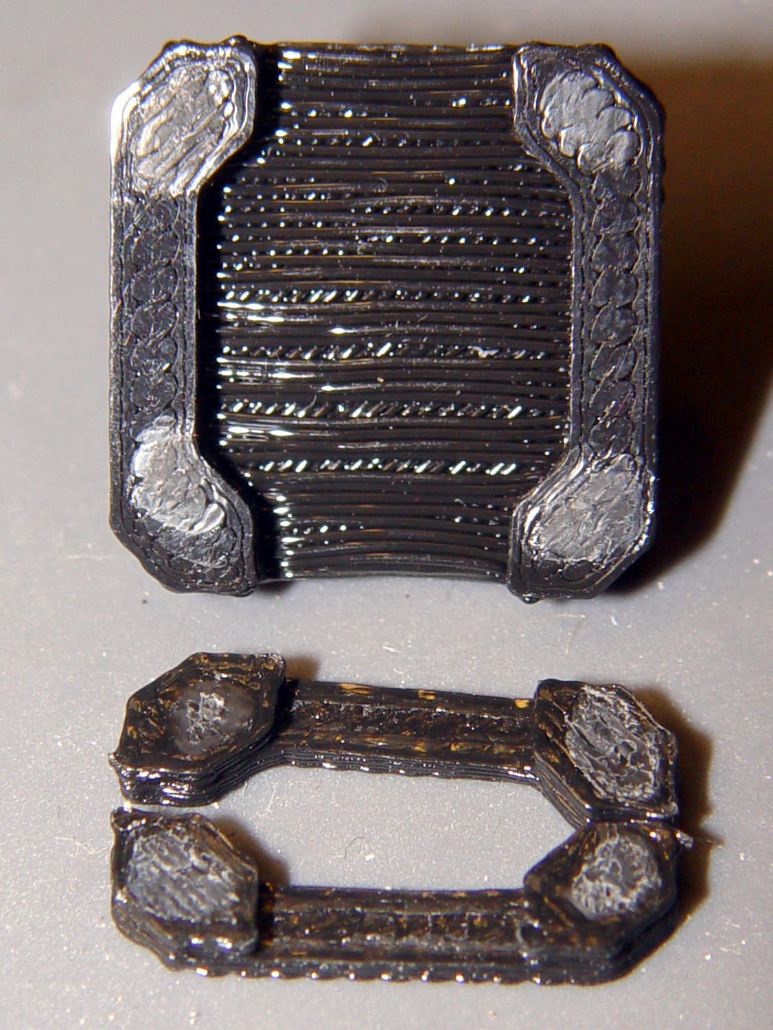
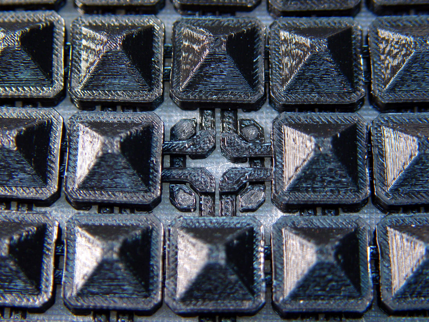
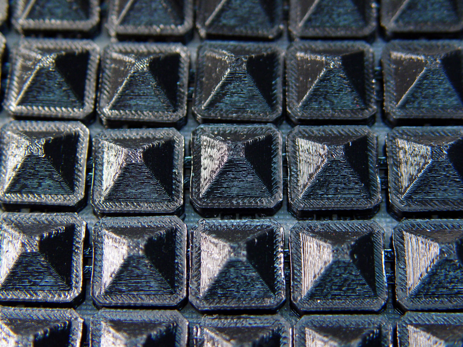
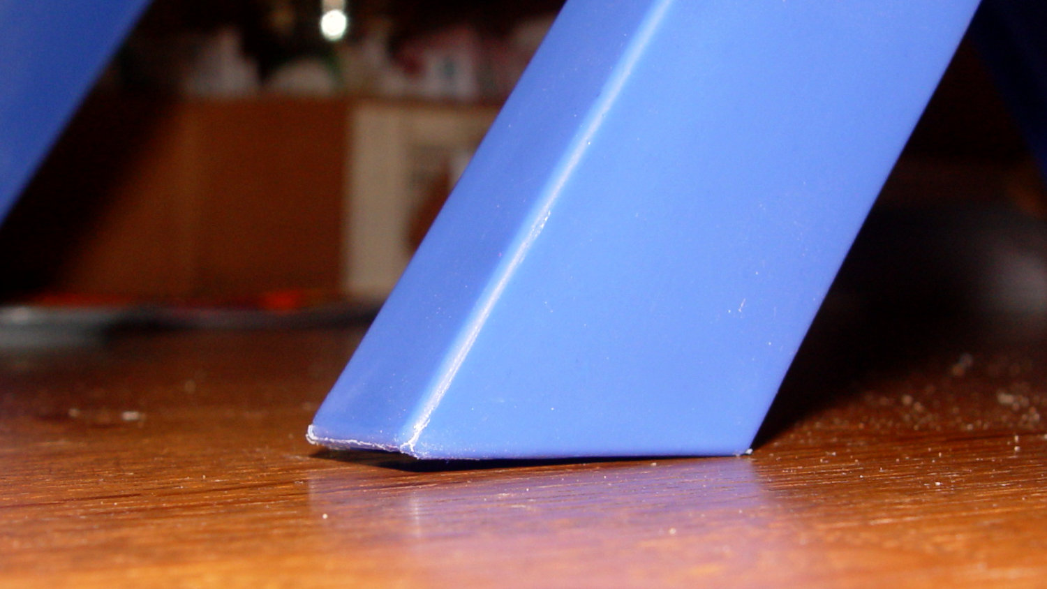
Having recently acquired a pair of photo lights and desirous of eliminating some desktop clutter, I decided this ancient incandescent (!) magnifying desk lamp had outlived its usefulness:

The styrene plastic shell isn’t quite so yellowed in real life, but it’s close.
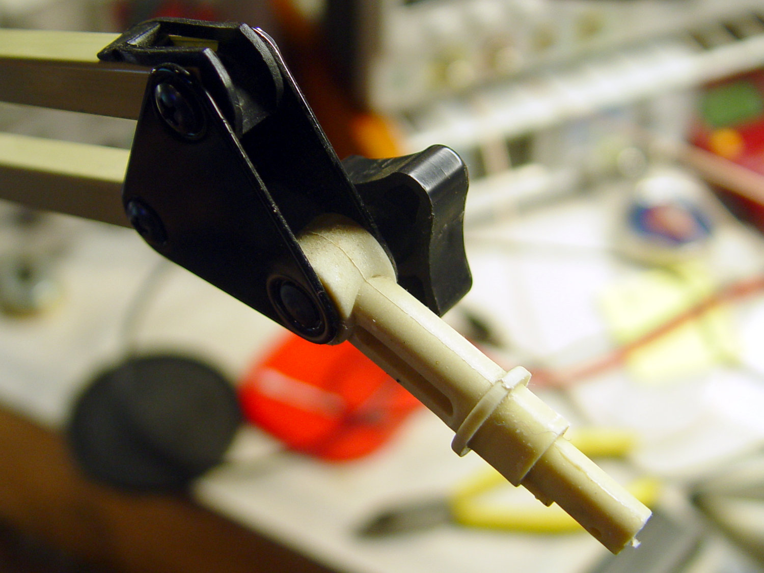
Stripping off the frippery reveals the tilt stem on the arm:
The photo lights have a tilt-pan mount intended for a camera’s cold (or hot) shoe, so I conjured an adapter from the vasty digital deep:

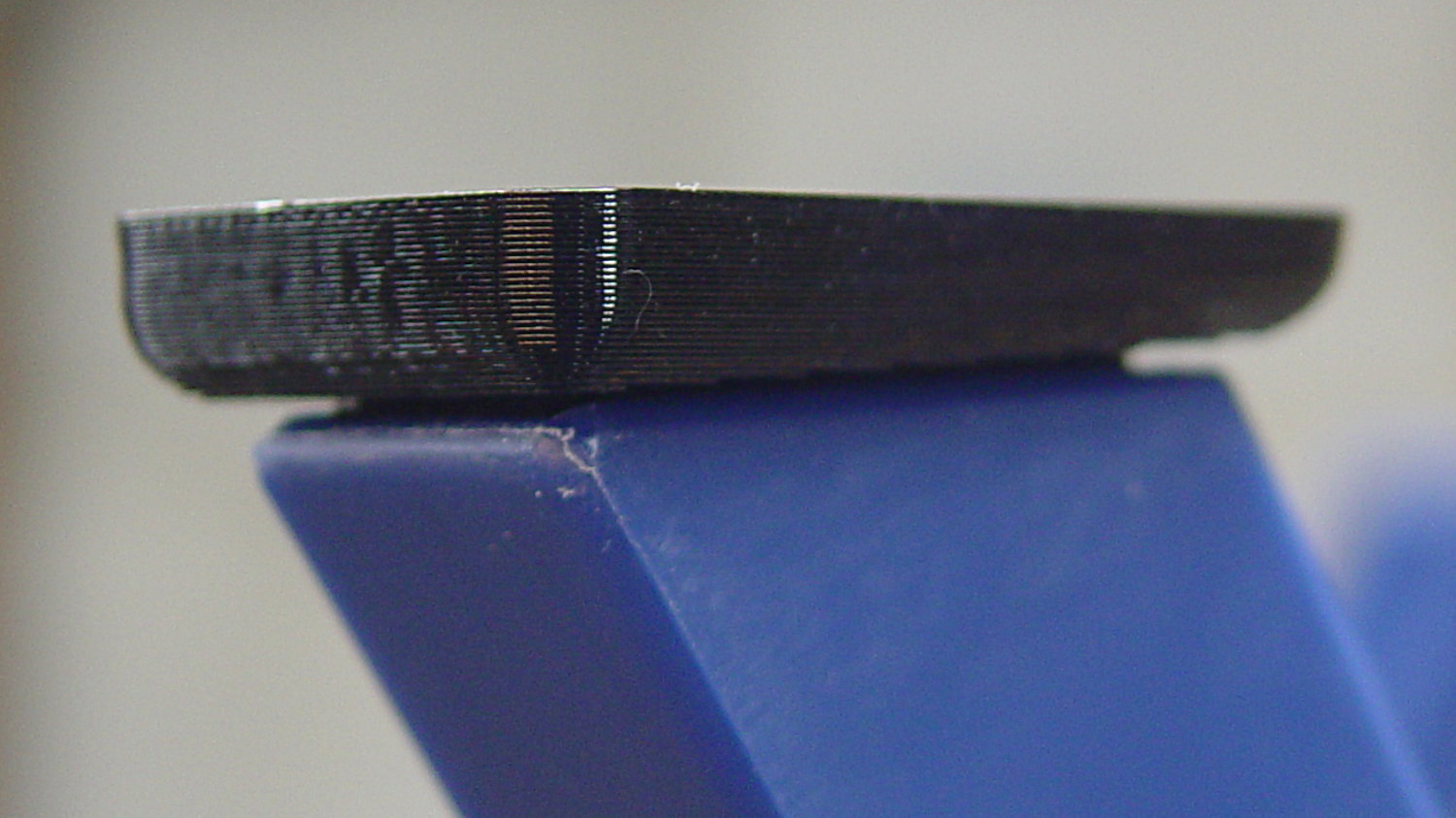
Printing with a brim improved platform griptivity:

Fortunately, the photo lights aren’t very heavy and shouldn’t apply too much stress to the layers across the joint between the stem and the cold shoe. Enlarging the stem perpendicular to the shoe probably didn’t make much difference, but it was easy enough.
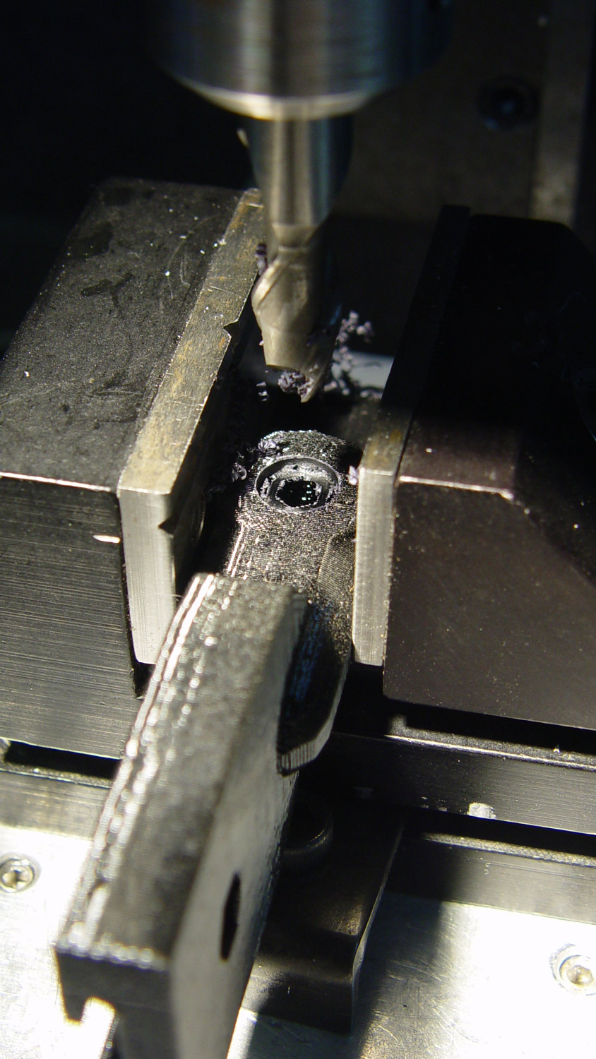
Of course, you (well, I) always forget a detail in the first solid model, so I had to mill recesses around the screw hole to clear the centering bosses in the metal arm plates:
Which let it fit perfectly into the arm:

The grody threads on the upper surface around the end of the slot came from poor bridging across a hexagon, so the new version has a simple and tity flat end. The slot is mostly invisible with the tilt-pan adapter in place, anyway.
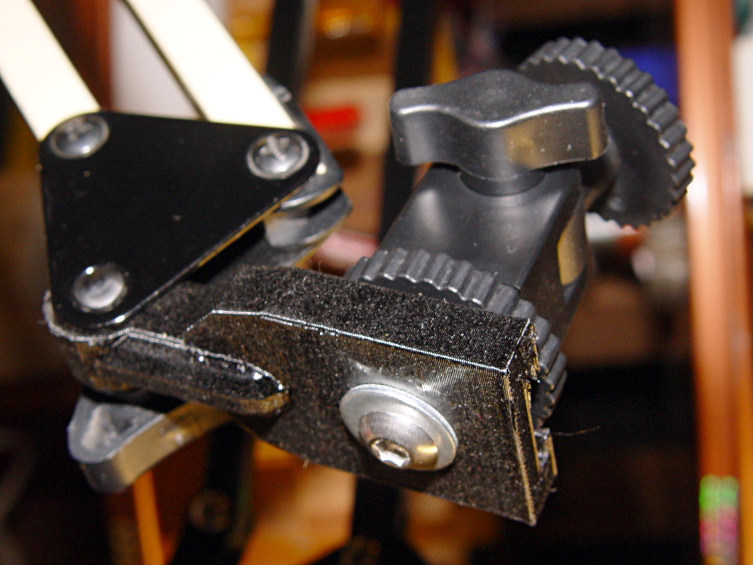
There being no need for a quick-disconnect fitting, a 1/4-20 button head screw locks the adapter in place:
I stripped the line cord from inside the arm struts and zip-tied the photo lamp’s wall wart cable to the outside:
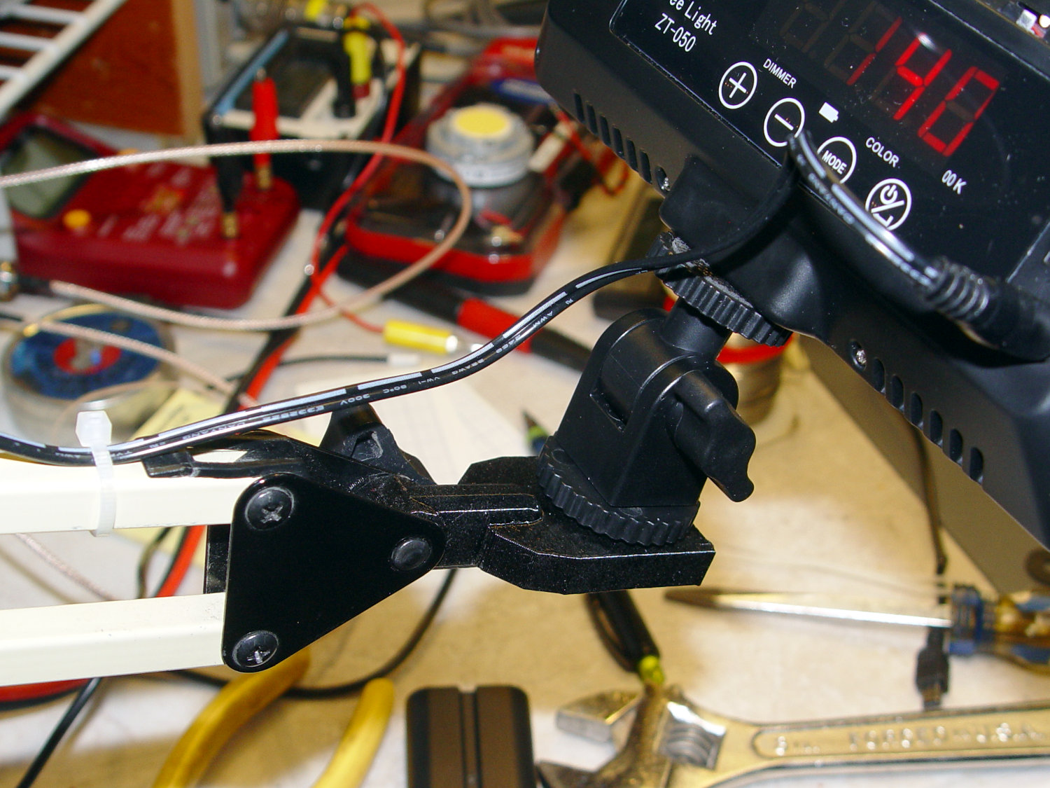
And then It Just Works™:

The lens and its retaining clips now live in the Big Box o’ Optical parts, where it may come in handy some day.
The OpenSCAD source code as a GitHub Gist:
| // Photo light mount for desk lamp arm | |
| // Ed Nisley – KE4ZNU | |
| // 2019-03 | |
| /* [Layout Options] */ | |
| Layout = "Build"; // [Show,Build] | |
| Part = "Mount"; // [LampArm,ShoeSocket,Mount] | |
| /* [Extrusion Parameters] */ | |
| ThreadWidth = 0.40; | |
| ThreadThick = 0.25; | |
| HoleWindage = 0.2; | |
| Protrusion = 0.1; | |
| //—– | |
| // Dimensions | |
| /* [Hidden] */ | |
| ID = 0; | |
| OD = 1; | |
| LENGTH = 2; | |
| /* [Dimensions] */ | |
| FrictionDisk = [4.0,16.5,11.0]; // squashed inside desk lamp arm frame | |
| Divots = [4.0,9.5,0.75]; // recesses for frame alignment bumps | |
| ArmLength = 30.0; // attached to disk | |
| ShoeWheelOD = 32.0; // lock wheel on photo lamp | |
| ShoeBase = [18.5,18.5,2.0] + [HoleWindage,HoleWindage,2*ThreadWidth]; // square base on photo lamp gimbal | |
| ShoeStem = [6.3,12.0,1.5]; // top slide clearance, ID = 1/4 inch screw | |
| ShoeBlock = [ShoeWheelOD,ShoeWheelOD,2*(ShoeBase.z + ShoeStem.z)]; // overall shoe block | |
| NumSides = 3*4; | |
| //—– | |
| // Useful routines | |
| function IntegerMultiple(Size,Unit) = Unit * ceil(Size / Unit); | |
| module PolyCyl(Dia,Height,ForceSides=0,Center=false) { // based on nophead's polyholes | |
| Sides = (ForceSides != 0) ? ForceSides : (ceil(Dia) + 2); | |
| FixDia = Dia / cos(180/Sides); | |
| cylinder(r=(FixDia + HoleWindage)/2,h=Height,$fn=Sides,center=Center); | |
| } | |
| //—– | |
| // Various Parts | |
| // Arm captured in disk lamp | |
| module LampArm() { | |
| difference() { | |
| union() { | |
| cylinder(d=FrictionDisk[OD],h=FrictionDisk[LENGTH],$fn=NumSides,center=true); | |
| hull() | |
| for (j=[-1,1]) | |
| translate([0,j*(FrictionDisk[OD]/2 – FrictionDisk[LENGTH]/2),0]) { | |
| rotate([0,90,0]) rotate(180/NumSides) | |
| cylinder(d=FrictionDisk[LENGTH]/cos(180/NumSides),h=ArmLength/2,$fn=NumSides); | |
| translate([ArmLength – FrictionDisk[LENGTH]/2,0,0]) | |
| sphere(d=FrictionDisk[LENGTH],$fn=NumSides); | |
| } | |
| } | |
| rotate(180/6) { | |
| PolyCyl(FrictionDisk[ID],FrictionDisk[LENGTH] + 2*Protrusion,6,Center=true); | |
| for (k=[-1,1]) | |
| translate([0,0,k*(FrictionDisk[LENGTH]/2 – Divots[LENGTH]/2)]) | |
| PolyCyl(Divots[OD],Divots[LENGTH] + Protrusion,6,Center=true); | |
| } | |
| } | |
| } | |
| // Basic hot shoe socket | |
| module ShoeSocket() { | |
| difference() { | |
| union() { | |
| cube(ShoeBlock,center=true); // overall blocky retainer | |
| translate([-ShoeBlock.x/2,0,0]) | |
| cylinder(d=ShoeBlock.x,h=ShoeBlock.z,$fn=NumSides,center=true); | |
| } | |
| translate([0,0,-2*ShoeBlock.z]) // screw hole throughout | |
| rotate(180/6) | |
| PolyCyl(ShoeStem[ID],4*ShoeBlock.z,6); | |
| translate([0,0,ShoeBase.z/2]) // base slot under pillar | |
| cube([ShoeBase.x,ShoeBase.y,ShoeBase.z],center=true); | |
| translate([ShoeBase.x/2,0,ShoeBase.z/2]) // base slot opening | |
| cube([ShoeBase.x,ShoeBase.y,ShoeBase.z],center=true); | |
| translate([ShoeStem[OD]/2,0,ShoeBase.z/2 + ShoeStem[LENGTH]]) // stem slot | |
| cube([2*ShoeStem[OD],ShoeStem[OD],2*ShoeStem[LENGTH]],center=true); | |
| } | |
| } | |
| // Stick parts together | |
| module Mount() { | |
| rotate([90,0,0]) | |
| LampArm(); | |
| translate([ArmLength + ShoeBlock.x/2 – Protrusion,0,0]) | |
| ShoeSocket(); | |
| } | |
| //—– | |
| // Build things | |
| if (Layout == "Build") { | |
| rotate([0,90,0]) | |
| translate([-(ArmLength + ShoeBlock.x),0,0]) | |
| Mount(); | |
| } | |
| if (Layout == "Show") | |
| if (Part == "LampArm") | |
| LampArm(); | |
| else if (Part == "ShoeSocket") | |
| ShoeSocket(); | |
| else if (Part == "Mount") | |
| Mount(); |
The original dimension doodles, made before I removed the stem and discovered the recesses around the screw hole: