The Smell of Molten Projects in the Morning

Ed Nisley's Blog: Shop notes, electronics, firmware, machinery, 3D printing, laser cuttery, and curiosities. Contents: 100% human thinking, 0% AI slop.

Tag: M2

Using and tweaking a Makergear M2 3D printer

  • Makergear M2: Octopi Camera Mount

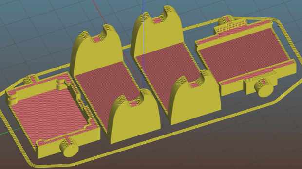
    Octopirint / Octopi works wonderfully well as a controller / G-Code feeder for my Makergear M2. After putting up with an ungainly mass of tape for far too long, I printed Toddman’s Pi Camera Mount:

    Pi Camera - M2 Mount - Slic3r
    Pi Camera – M2 Mount – Slic3r

    Which snapped together exactly like it should:

    Makergear M2 - Pi Camera Mount
    Makergear M2 – Pi Camera Mount

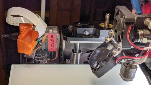
    A strip of double-sided foam tape attaches it to the Pi’s case, which is Velcro-ed to the M2’s frame. The cable may be too long, but avoids sharp bends on the way out of the case.

    The whole lashup works fine:

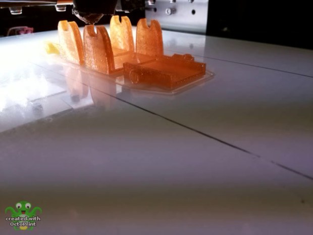
    Pi Camera - M2 Mount - Octopi timelapse
    Pi Camera – M2 Mount – Octopi timelapse

    That’s a second set intended for the CNC 3018-Pro, but it didn’t fit quite as well. The B brackets are slightly too long (or their pivots are slightly too close to their base) to allow the C plates to turn 90° to the mount:

    Pi Camera - M2 Mount - Config 2 diagram
    Pi Camera – M2 Mount – Config 2 diagram

    Nothing one can’t fix with nibbling & filing, but I long for parametric designs …

  • CNC 3018-Pro: Hard Drive Platter Fixture

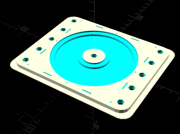
    A variation on the CD fixture produces a 3.5 inch hard drive platter fixture:

    Platter Fixtures - Hard Drive on 3018
    Platter Fixtures – Hard Drive on 3018

    Which needed just a touch of milling for a snug fit around the platter:

    CNC 3018-Pro - HD platter fixture - test fit
    CNC 3018-Pro – HD platter fixture – test fit

    Tape it down on the 3018’s platform, set XY=0 at the center, and It Just Works™:

    CNC 3018-Pro - HD platter fixture - 70 g
    CNC 3018-Pro – HD platter fixture – 70 g

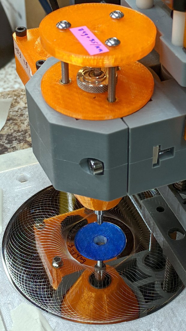
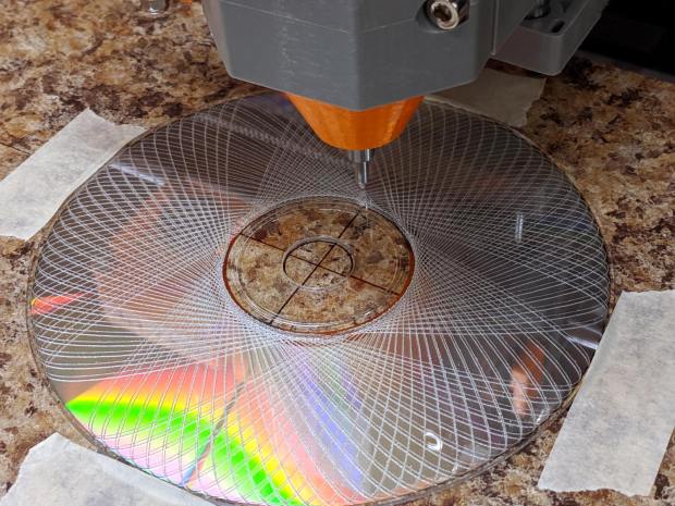
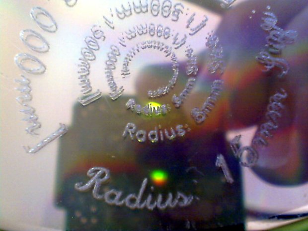
    The rather faint line shows engraving at -1.0 mm = 70 g downforce isn’t quite enough. Another test with the same pattern at -3.0 mm = 140 g came out better:

    CNC 3018-Pro - HD platter fixture - 140 g
    CNC 3018-Pro – HD platter fixture – 140 g

    It’s in the same OpenSCAD file as the CD fixture, in the unlikely event you need one.

  • CNC 3018-Pro: Tape-Down Platter Fixture

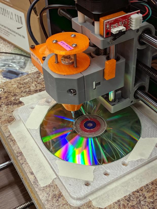
    Diamond drag engraving doesn’t put much sideways force on the platters, so taping the CD in place suffices to hold it:

    CNC 3018-Pro - CD taped to platform
    CNC 3018-Pro – CD taped to platform

    Wrapping a flange around the screw-down platter fixture provides plenty of surface area for tape:

    Platter Fixtures - CD on 3018 - tape flange
    Platter Fixtures – CD on 3018 – tape flange

    Which looks exactly as you think it would in real life:

    CNC 3018-Pro - CD fixture - taped
    CNC 3018-Pro – CD fixture – taped

    Admittedly, masking tape doesn’t look professional, but it’s low-profile, cheap and works perfectly. Blue painter’s tape for the “permanent” hold-down strips on the platform would be a colorful upgrade.

    It’s centered on the platform at the XY=0 origin in the middle of the XY travel limits, with edges aligned parallel to the axes. Homing the 3018 and moving to XY=0 puts the tool point directly over the center of the CD without any fussy alignment.

    The blue-and-red rings around the center hole assist probe camera alignment, whenever that’s necessary.

    The OpenSCAD source code as a GitHub Gist:

    // Machining fixtures for CD and hard drive platters
    // Ed Nisley KE4ZNU February … September 2016
    // 2019-08 split from tube base models
    PlatterName = "CD"; // [3.5inch,CD]
    CNCName = "3018"; // [3018,Sherline]
    TapeFlange = true; // Generate tape attachment
    PlateThick = 5.0; // [3.0,5.0,10.0,15.0]
    RecessDepth = 4.0; // [0.0,2.0,4.0]
    //- Extrusion parameters must match reality!
    /* [Hidden] */
    ThreadThick = 0.25;
    ThreadWidth = 0.40;
    HoleWindage = 0.2;
    Protrusion = 0.1; // make holes end cleanly
    inch = 25.4;
    function IntegerMultiple(Size,Unit) = Unit * ceil(Size / Unit);
    module PolyCyl(Dia,Height,ForceSides=0) { // based on nophead's polyholes
    Sides = (ForceSides != 0) ? ForceSides : (ceil(Dia) + 2);
    FixDia = Dia / cos(180/Sides);
    cylinder(d=(FixDia + HoleWindage),h=Height,$fn=Sides);
    }
    ID = 0;
    OD = 1;
    LENGTH = 2;
    //———————-
    // Dimensions
    P_NAME = 0; // platter name
    P_ID = 1; // … inner diameter
    P_OD = 2; // … outer diameter
    P_THICK = 3; // … thickness
    PlatterData = [
    ["3.5inch", 25.0, 95.0, 1.75],
    ["CD", 15.0, 120.0, 1.20],
    ];
    PlatterSides = 3*4*5; // polygon approximation
    B_NAME = 0; // machine name
    B_OC = 1; // … platform screw OC, use small integer for slot
    B_STUD = 2; // … screw OD clearance
    BaseData = [
    ["3018", [5.0, 45.0], 6.0], // slots along X axis
    ["Sherline", [1.16*inch,1.16*inch], 5.0], // tooling plate
    ];
    PlateRound = 10.0; // corner radius
    FlangeSize = [5.0,5.0,3*ThreadThick]; // all-around tape flange
    //– calculate values based on input parameters
    PI = search([PlatterName],PlatterData,1,0)[P_NAME]; // get platter index
    echo(str("Platter: ",PlatterName));
    Platter = [PlatterData[PI][P_ID],
    PlatterData[PI][P_OD],
    PlatterData[PI][P_THICK]];
    BI = search([CNCName],BaseData,1,0)[B_NAME]; // get base index
    echo(str("Machine: ",CNCName));
    AlignOC = IntegerMultiple(Platter[OD],10);
    echo(str("Alignment pip offset: ±",AlignOC/2));
    AlignSlot = [3*ThreadWidth,10.0,3*ThreadThick];
    StudClear = BaseData[BI][B_STUD]; // … clearance
    StudOC = [IntegerMultiple(AlignOC + 2*StudClear,BaseData[BI][B_OC].x), // … screw spacing
    BaseData[BI][B_OC].y];
    echo(str("Stud spacing: ",StudOC));
    NumStuds = [2,1 + 2*floor(Platter[OD] / StudOC.y)]; // holes only along ±X edges
    echo(str("Stud holes: ",NumStuds));
    BasePlate = [(20 + StudOC.x*ceil(Platter[OD] / StudOC.x)),
    (10 + AlignOC),
    PlateThick];
    echo(str("Plate: ",BasePlate));
    Flange = [BasePlate.x + 2*FlangeSize.x,BasePlate.y + 2*FlangeSize.y,FlangeSize.z];
    echo(str("Flange: ",Flange));
    //———————-
    // Drilling fixture for disk platters
    module PlatterFixture() {
    difference() {
    union() {
    hull() // basic plate shape
    for (i=[-1,1], j=[-1,1])
    translate([i*(BasePlate.x/2 – PlateRound),j*(BasePlate.y/2 – PlateRound),0])
    cylinder(r=PlateRound,h=BasePlate.z,$fn=4*4);
    if (TapeFlange)
    hull()
    for (i=[-1,1], j=[-1,1])
    translate([i*(Flange.x/2 – PlateRound),
    j*(Flange.y/2 – PlateRound),
    0])
    cylinder(r=PlateRound,h=FlangeSize.z,$fn=4*4);
    }
    for (i=[-1,0,1], j=[-1,0,1]) // origin pips
    translate([i*AlignOC/2,j*AlignOC/2,BasePlate.z – 2*ThreadThick])
    cylinder(d=4*ThreadWidth,h=1,$fn=6);
    for (i=[-1,1], j=[-1,1]) { // alignment slots
    translate([i*(AlignOC + AlignSlot.x)/2,
    j*Platter[OD]/4,
    (BasePlate.z – AlignSlot.z/2 + Protrusion/2)])
    cube(AlignSlot + [0,0,Protrusion],center=true);
    translate([i*Platter[OD]/4,
    j*(AlignOC + AlignSlot.x)/2,
    (BasePlate.z – AlignSlot.z/2 + Protrusion/2)])
    rotate(90)
    cube(AlignSlot + [0,0,Protrusion],center=true);
    }
    for (i=[-1,1], j=[-floor(NumStuds.y/2):floor(NumStuds.y/2)]) // mounting stud holes
    translate([i*StudOC.x/2,j*StudOC.y/2,-Protrusion])
    rotate(180/6)
    PolyCyl(StudClear,BasePlate.z + 2*Protrusion,6);
    translate([0,0,-Protrusion]) // center clamp hole
    rotate(180/6)
    PolyCyl(StudClear,BasePlate.z + 2*Protrusion,6);
    translate([0,0,BasePlate.z – Platter[LENGTH]]) // disk locating recess
    rotate(180/PlatterSides)
    linear_extrude(height=(Platter[LENGTH] + Protrusion),convexity=2)
    difference() {
    circle(d=(Platter[OD] + 2*HoleWindage),$fn=PlatterSides);
    circle(d=Platter[ID] – HoleWindage,$fn=PlatterSides);
    }
    translate([0,0,BasePlate.z – RecessDepth]) // drilling recess
    rotate(180/PlatterSides)
    linear_extrude(height=(RecessDepth + Protrusion),convexity=2)
    difference() {
    circle(d=(Platter[OD] – 10),$fn=PlatterSides);
    circle(d=(Platter[ID] + 10),$fn=PlatterSides);
    }
    }
    }
    //———————-
    // Build it
    PlatterFixture();

  • CNC 3018-Pro: LM6UU Linear-bearing Diamond Drag Bit Holder

    The CNC 3018-Pro normally holds a small DC motor with a nicely cylindrical housing,so this was an easy adaptation of the MPCNC’s diamond drag bit holder:

    CNC 3018-Pro - Diamond bit - overview
    CNC 3018-Pro – Diamond bit – overview

    The lip around the bottom part rests atop the tool clamp, with the spring reaction plate sized to clear the notch in the Z-axis stage.

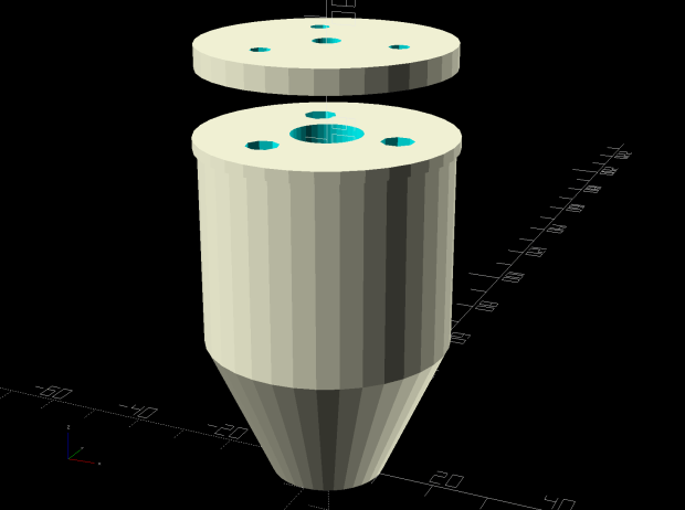
    The solid model looks about like you’d expect:

    Diamond Scribe - Mount - solid model
    Diamond Scribe – Mount – solid model

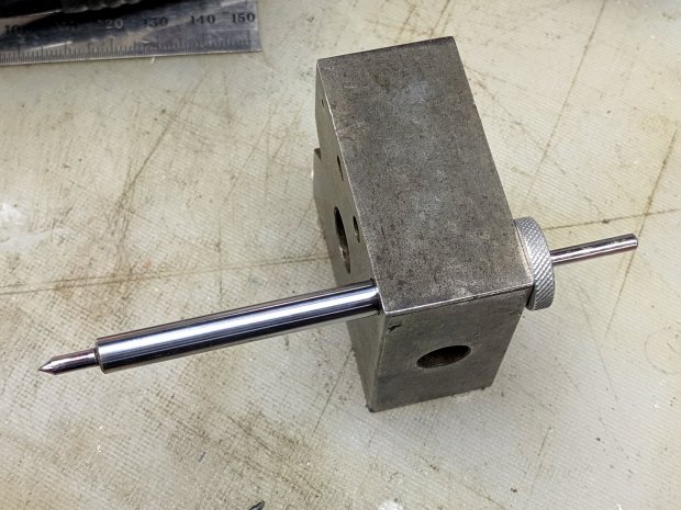
    The New Thing compared to the MPCNC holder is wrapping LM6UU bearings around an actual 6 mm shaft, instead of using LM3UU bearings for the crappy diamond bit shank:

    CNC 3018-Pro - Diamond bit - epoxy curing
    CNC 3018-Pro – Diamond bit – epoxy curing

    I cut the shank in two pieces, epoxied them into 3 mm holes drilled into the 6 mm shaft, then epoxied the knurled stop ring on the end. The ring is curing in the bench block to stay perpendicular to the 6 mm shaft.

    The spring constant is 55 g/mm and it’s now set for 125 g preload:

    CNC 3018-Pro - Diamond bit - force measurement
    CNC 3018-Pro – Diamond bit – force measurement

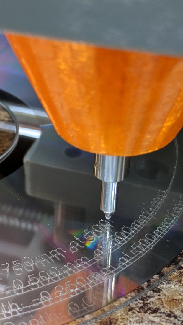
    A quick test says all the parts have begun flying in formation:

    CNC 3018-Pro - Diamond bit - test CD
    CNC 3018-Pro – Diamond bit – test CD

    It’s definitely more rigid than the MPCNC!

    The OpenSCAD source code as a GitHub Gist:

    // Diamond Scribe in linear bearings for CNC3018
    // Ed Nisley KE4ZNU – 2019-08-9
    Layout = "Build"; // [Build, Show, Base, Mount, Plate]
    /* [Hidden] */
    ThreadThick = 0.25; // [0.20, 0.25]
    ThreadWidth = 0.40; // [0.40, 0.40]
    /* [Hidden] */
    Protrusion = 0.1; // [0.01, 0.1]
    HoleWindage = 0.2;
    inch = 25.4;
    function IntegerMultiple(Size,Unit) = Unit * ceil(Size / Unit);
    ID = 0;
    OD = 1;
    LENGTH = 2;
    //- Adjust hole diameter to make the size come out right
    module PolyCyl(Dia,Height,ForceSides=0) { // based on nophead's polyholes
    Sides = (ForceSides != 0) ? ForceSides : (ceil(Dia) + 2);
    FixDia = Dia / cos(180/Sides);
    cylinder(r=(FixDia + HoleWindage)/2,h=Height,$fn=Sides);
    }
    //- Dimensions
    // Knife holder & suchlike
    ScribeOD = 3.0; // diamond scribe shaft
    Bearing = [6.0,12.0,19.0]; // linear bearing body, ID = shaft diameter
    Spring = [4.5,5.5,3*ThreadThick]; // compression spring around shaft, LENGTH = socket depth
    //Spring = [9.5,10.0,3*ThreadThick]; // compression spring around shaft, LENGTH = socket depth
    WallThick = 4.0; // minimum thickness / width
    Screw = [3.0,6.75,25.0]; // holding it all together, OD = washer
    Insert = [3.0,5.0,8.0]; // brass insert
    //Insert = [4.0,6.0,10.0];
    Clamp = [43.2,44.0,34.0]; // tool clamp ring, OD = clearance around top
    LipHeight = IntegerMultiple(2.0,ThreadThick); // above clamp for retaining
    BottomExtension = 25.0; // below clamp to reach workpiece
    MountOAL = LipHeight + Clamp[LENGTH] + BottomExtension; // total mount length
    echo(str("Mount OAL: ",MountOAL));
    Plate = [1.5*ScribeOD,Clamp[ID] – 0*2*WallThick,WallThick]; // spring reaction plate
    NumScrews = 3;
    ScrewBCD = Bearing[OD] + Insert[OD] + 2*WallThick;
    echo(str("Retainer max OD: ",ScrewBCD – Screw[OD]));
    NumSides = 9*4; // cylinder facets (multiple of 3 for lathe trimming)
    // Basic mount shape
    module CNC3018Base() {
    translate([0,0,MountOAL – LipHeight])
    cylinder(d=Clamp[OD],h=LipHeight,$fn=NumSides);
    translate([0,0,MountOAL – LipHeight – Clamp[LENGTH] – Protrusion])
    cylinder(d=Clamp[ID],h=(Clamp[LENGTH] + 2*Protrusion),$fn=NumSides);
    cylinder(d1=Bearing[OD] + 2*WallThick,d2=Clamp[ID],h=BottomExtension + Protrusion,$fn=NumSides);
    }
    // Mount with holes & c
    module Mount() {
    difference() {
    CNC3018Base();
    translate([0,0,-Protrusion]) // bearing
    PolyCyl(Bearing[OD],2*MountOAL,NumSides);
    for (i=[0:NumScrews – 1]) // clamp screws
    rotate(i*360/NumScrews)
    translate([ScrewBCD/2,0,MountOAL – Clamp[LENGTH]])
    rotate(180/8)
    PolyCyl(Insert[OD],Clamp[LENGTH] + Protrusion,8);
    }
    }
    module SpringPlate() {
    difference() {
    cylinder(d=Plate[OD],h=Plate[LENGTH],$fn=NumSides);
    translate([0,0,-Protrusion])
    PolyCyl(Plate[ID],2*MountOAL,NumSides);
    translate([0,0,Plate[LENGTH] – Spring[LENGTH]]) // spring retainer
    PolyCyl(Spring[OD],Spring[LENGTH] + Protrusion,NumSides);
    for (i=[0:NumScrews – 1]) // clamp screws
    rotate(i*360/NumScrews)
    translate([ScrewBCD/2,0,-Protrusion])
    rotate(180/8)
    PolyCyl(Screw[ID],2*MountOAL,8);
    }
    }
    //—–
    // Build it
    if (Layout == "Base")
    CNC3018Base();
    if (Layout == "Mount")
    Mount();
    if (Layout == "Plate")
    SpringPlate();
    if (Layout == "Show") {
    Mount();
    translate([0,0,1.25*MountOAL])
    rotate([180,0,0])
    SpringPlate();
    }
    if (Layout == "Build") {
    translate([0,-0.75*Clamp[OD],MountOAL])
    rotate([180,0,0])
    Mount();
    translate([0,0.75*Plate[OD],0])
    SpringPlate();
    }

  • CNC 3018-Pro: Probe Camera Case for Anonymous USB Camera

    The anonymous USB camera I used with the stereo zoom microscope not only works with VLC, but also with bCNC, and it has a round PCB with ears:

    CNC 3018-Pro - Probe Camera - PCB
    CNC 3018-Pro – Probe Camera – PCB

    Which suggested putting it in a ball mount for E-Z aiming:

    CNC 3018-Pro - Probe Camera - ball mount
    CNC 3018-Pro – Probe Camera – ball mount

    Black filament snippets serve as alignment pins to hold the ball halves together while they’re getting clamped. They’re epoxied into the upper half of the ball, because who knows when I’ll need to harvest the camera.

    The clamp mount descends from the Tour Easy Daytime Running Lights, with more screws and less fancy shaping:

    USB Camera - Round PCB Mount - solid model - build
    USB Camera – Round PCB Mount – solid model – build

    The clamp pieces fit around the ball with four M3 screws providing the clamping force:

    USB Camera - Round PCB Mount - solid model sectioned
    USB Camera – Round PCB Mount – solid model sectioned

    The whole affair sticks onto the Z axis carrier with double-sided foam tape:

    CNC 3018-Pro - Probe Camera - alignment
    CNC 3018-Pro – Probe Camera – alignment

    It barely clears the strut on the -X side of the carriage, although it does stick out over the edge of the chassis.

    After the fact, I tucked a closed-cell foam ring between the lens threads and the ball housing to stabilize the lens; the original camera glued the thing in place, but some fiddly alignment & focusing lies ahead:

    Alignment mirror - collimation
    Alignment mirror – collimation

    It’s worth noting that the optical axis of these cheap cameras rarely coincides with the physical central axis of the lens. This one requires a jaunty tilt, although it’s not noticeable in any of the pictures I tried to take.

    All in all, this one works just like the probe camera on the MPCNC.

    The OpenSCAD source code as a GitHub Gist:

    // CNC 3018-Pro Probe Camera mount for anonymous USB camera
    // Ed Nisley KE4ZNU – August 2019
    Layout = "Show"; // [Show, Build, Ball, Clamp, Bracket, Mount]
    //——-
    //- Extrusion parameters must match reality!
    // Print with 2 shells
    /* [Hidden] */
    ThreadThick = 0.25;
    ThreadWidth = 0.40;
    HoleWindage = 0.2;
    Protrusion = 0.1; // make holes end cleanly
    function IntegerMultiple(Size,Unit) = Unit * ceil(Size / Unit);
    inch = 25.4;
    ID = 0;
    OD = 1;
    LENGTH = 2;
    //——-
    // Dimensions
    //– Camera
    PCBThick = 1.2;
    PCBDia = 25.0;
    KeySize = [28.0,8.5,IntegerMultiple(PCBThick,ThreadThick)];
    KeyOffset = [0.0,2.0,0.0];
    KeyRadius = IntegerMultiple(sqrt(pow(KeySize.y – KeyOffset.y,2) + pow(KeySize.x/2,2)),0.01);
    echo(str("Key radius: ",KeyRadius));
    Lens = [14.0,18.0,25.0];
    BallID = PCBDia;
    BallOD = IntegerMultiple(2*KeyRadius,5.0);
    echo(str("Ball OD: ",BallOD));
    WallThick = 3.0;
    CableOD = 3.75;
    NumPins = 3;
    Pin = [1.75,1.8,5.0];
    Screw = [
    3.0,6.8,25.0 // M3 ID=thread, OD=washer, LENGTH=below head
    ];
    RoundRadius = IntegerMultiple(Screw[OD]/2,1.0); // corner rounding
    ClampSize = [BallOD + 2*WallThick,BallOD + 2*WallThick,20.0];
    echo(str("Clamp: ",ClampSize));
    MountSize = [5.0,BallOD,25.0];
    MountClearance = 1.0; // distance between clamp and mount
    Kerf = 2*ThreadThick;
    ScrewOC = [ClampSize.x – 2*RoundRadius,ClampSize.y – 2*RoundRadius];
    echo(str("Screw OC: ",ScrewOC));
    Insert = [ // brass insert: body, knurl,length
    3.9,4.9,8.0
    ];
    UseInsert = false;
    NumSides = 12*4;
    //——-
    module PolyCyl(Dia,Height,ForceSides=0) { // based on nophead's polyholes
    Sides = (ForceSides != 0) ? ForceSides : (ceil(Dia) + 2);
    FixDia = Dia / cos(180/Sides);
    cylinder(r=(FixDia + HoleWindage)/2,
    h=Height,
    $fn=Sides);
    }
    //——-
    // Components
    module CamBall(Section="Both") {
    Offset = (Section == "Both") ? 0 :
    (Section == "Upper") ? BallOD/2 :
    (Section == "Lower") ? -BallOD/2 :
    0;
    render(convexity=4)
    intersection(convexity = 3) {
    difference() {
    sphere(d=BallOD,$fn=NumSides);
    sphere(d=BallID,$fn=NumSides); // interior
    PolyCyl(CableOD,2*BallOD,8); // cable & lens holes
    translate([0,0,-Lens[LENGTH]])
    PolyCyl(Lens[OD],Lens[LENGTH],NumSides);
    translate([0,0,-PCBThick])
    PolyCyl(PCBDia,PCBThick,NumSides);
    translate(KeyOffset + [0,-KeySize.y/2,-PCBThick/2]) // PCB key
    cube(KeySize,center=true);
    for (i=[0:NumPins – 1])
    rotate(i*360/NumPins)
    translate([0,-(BallID + BallOD)/4,-Pin[LENGTH]/2])
    PolyCyl(Pin[OD],Pin[LENGTH],6);
    }
    translate([0,0,Offset])
    cube([BallOD,BallOD,BallOD] + 2*[Protrusion,Protrusion,0],center=true);
    }
    }
    module Clamp(Section="Both") {
    Offset = (Section == "Both") ? 0 :
    (Section == "Upper") ? ClampSize.z/2 :
    (Section == "Lower") ? -ClampSize.z/2 :
    0;
    render(convexity=4)
    intersection() {
    difference() {
    hull()
    for (i=[-1,1], j=[-1,1])
    translate([i*ScrewOC.x/2,j*ScrewOC.y/2,0])
    cylinder(r=RoundRadius,h=ClampSize.z,$fn=NumSides,center=true);
    sphere(d=BallOD + 2*HoleWindage,$fn=NumSides); // space around camera ball
    for (i=[-1,1], j=[-1,1]) // screws
    translate([i*ScrewOC.x/2,j*ScrewOC.y/2,-ClampSize.z])
    PolyCyl(Screw[ID],2*ClampSize.z,6);
    if (UseInsert)
    for (i=[-1,1], j=[-1,1]) // inserts
    translate([i*ScrewOC.x/2,j*ScrewOC.y/2,-(ClampSize.z/2 + Protrusion)])
    PolyCyl(Insert[OD],Insert[LENGTH] + Protrusion,8);
    cube([2*ClampSize.x,2*ClampSize.y,Kerf],center=true); // clamping gap
    }
    translate([0,0,Offset])
    cube([ClampSize.x,ClampSize.y,ClampSize.z] + 2*[Protrusion,Protrusion,0],center=true);
    }
    }
    module Bracket() {
    translate([ClampSize.x/2 + MountSize.x/2 + MountClearance,0,MountSize.z/2 – ClampSize.z/2])
    cube(MountSize,center=true);
    translate([ClampSize.x/2 + MountClearance/2,0,-(ClampSize.z + Kerf)/4])
    cube([MountClearance + 2*Protrusion,MountSize.y,(ClampSize.z – Kerf)/2],center=true);
    }
    module Mount() {
    union() {
    Clamp("Lower");
    Bracket();
    }
    }
    //——-
    // Build it!
    if (Layout == "Ball")
    CamBall();
    if (Layout == "Clamp")
    Clamp();
    if (Layout == "Bracket")
    Bracket();
    if (Layout == "Mount")
    Mount();
    if (Layout == "Show") {
    difference() {
    union() {
    color("Purple")
    Clamp("Upper");
    Mount();
    color("LimeGreen")
    CamBall();
    }
    rotate([0,0,45])
    translate([-ClampSize.x,0,0])
    cube(2*ClampSize,center=true);
    }
    }
    if (Layout == "Build") {
    Gap = 0.6;
    translate([-Gap*BallOD,Gap*BallOD,0])
    CamBall("Upper");
    translate([-Gap*BallOD,-Gap*BallOD,0])
    rotate([0,180,0])
    CamBall("Lower");
    translate([Gap*ClampSize.x,-Gap*ClampSize.y,ClampSize.z/2])
    rotate([0,180,0])
    Clamp("Upper");
    translate([Gap*ClampSize.x,Gap*ClampSize.y,ClampSize.z/2]) {
    rotate(180)
    Mount();
    }
    }

  • CNC 3018-Pro: Probe Camera Case for Logitch QuickCam Pro 5000

    The ball-shaped Logitch QuickCam Pro 5000 has a rectangular PCB, so conjuring a case wasn’t too challenging:

    Probe Camera Case - Logitech QuickCam Pro 5000 - bottom
    Probe Camera Case – Logitech QuickCam Pro 5000 – bottom

    That’s more-or-less matte black duct tape to cut down reflections.

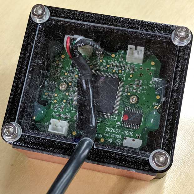
    The top side has a cover made from scuffed acrylic scrap:

    Probe Camera Case - Logitech QuickCam Pro 5000 - top
    Probe Camera Case – Logitech QuickCam Pro 5000 – top

    The corners are slightly rounded to fit under the screw heads holding it in place.

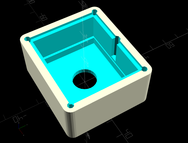
    The solid model shows off the internal ledge positioning the PCB so the camera lens housing rests on the floor:

    3018 Probe Camera Mount - solid model
    3018 Probe Camera Mount – solid model

    The notch lets the cable out, while keeping it in one place and providing some strain relief.

    I though if a camera was recognized by V4L2 and worked with VLC, it was good to go:

    Logitech QuickCam Pro 5000 - short focus
    Logitech QuickCam Pro 5000 – short focus

    Regrettably, it turns out the camera has a pixel format incompatible with the Python opencv interface used by bCNC. This may have something to do with running the code on a Raspberry Pi, rather than an x86 box.

    The camera will surely come in handy for something else, especially with such a cute case.

    The OpenSCAD source code as a GitHub Gist:

    // Probe Camera Mount for CNC 3018-Pro Z Axis
    // Ed Nisley – KE4ZNU – 2019-08
    Layout = "Block"; // [Show,Build,Block]
    Support = false;
    /* [Hidden] */
    ThreadThick = 0.20;
    ThreadWidth = 0.40;
    HoleWindage = 0.2;
    Protrusion = 0.1; // make holes end cleanly
    function IntegerMultiple(Size,Unit) = Unit * ceil(Size / Unit);
    ID = 0;
    OD = 1;
    LENGTH = 2;
    inch = 25.4;
    //———————-
    // Dimensions
    PCB = [45.0,38.0,1.5]; // Logitech QuickCam Pro 5000 ball camera
    PCBLip = 1.0; // max non-component border
    PCBChamfer = 3.0; // cut along XY axes for corner bevel
    PCBClearTop = 15.0; // cables & connectors
    PCBClearSides = [0.5,0.5]; // irregular edges & comfort zone
    PCBClearBelow = 5.0; // lens support bracket rests on floor
    Lens = [11.5,14.2,3.0]; // LENGTH = beyond PCBClearBelow bracket
    LensOffset = [-1.5,0.0,0]; // distance from center of board
    CableOD = 4.5;
    BaseThick = Lens[LENGTH];
    Screw = [
    3.0,6.8,18.0 // M3 OD=washer, LENGTH=below head
    ];
    RoundRadius = IntegerMultiple(Screw[OD]/2,1.0); // corner rounding
    ScrewOC = [PCB.x + 2*sqrt(Screw[OD]),PCB.y + 2*sqrt(Screw[OD])];
    echo(str("Screw OC: ",ScrewOC));
    Lid = [ScrewOC.x,ScrewOC.y,1.0/16.0 * inch]; // top cover plate
    echo(str("Lid: ",Lid));
    BlockSize = [ScrewOC.x + 2*RoundRadius,ScrewOC.y + 2*RoundRadius,
    BaseThick + PCBClearBelow + PCB.z + PCBClearTop + Lid.z];
    echo(str("Block: ",BlockSize));
    NumSides = 2*3*4;
    //———————-
    // Useful routines
    module PolyCyl(Dia,Height,ForceSides=0) { // based on nophead's polyholes
    Sides = (ForceSides != 0) ? ForceSides : (ceil(Dia) + 2);
    FixDia = Dia / cos(180/Sides);
    cylinder(r=(FixDia + HoleWindage)/2,
    h=Height,
    $fn=Sides);
    }
    // Basic shapes
    // Overall block
    module Block() {
    difference() {
    hull()
    for (i=[-1,1], j=[-1,1])
    translate([i*ScrewOC.x/2,j*ScrewOC.y/2,0])
    cylinder(r=RoundRadius,h=BlockSize.z,$fn=NumSides);
    for (i=[-1,1], j=[-1,1]) // corner screws
    translate([i*ScrewOC.x/2,j*ScrewOC.y/2,BlockSize.z – Screw[LENGTH]])
    cylinder(d=Screw[ID],h=2*Screw[LENGTH],$fn=8); // cylinder = undersized
    translate(LensOffset + [0,0,-Protrusion]) // lens body
    PolyCyl(Lens[OD],2*BlockSize.z,NumSides);
    translate([0,0,BlockSize.z/2 + BaseThick]) // PCB lip on bottom
    cube([PCB.x – 2*PCBLip,PCB.y,BlockSize.z],center=true);
    translate([0,0,BlockSize.z/2 + BaseThick + PCBClearBelow]) // PCB clearance
    cube([PCB.x + 2*PCBClearSides.x,PCB.y + 2*PCBClearSides.y,BlockSize.z],center=true);
    translate([0,0,BlockSize.z – Lid.z/2]) // lid recess
    cube(Lid + [0,0,Protrusion],center=true);
    translate([0,Lid.y/2 – CableOD/2,BaseThick + PCBClearBelow + PCB.z]) // cable exit
    hull()
    for (j=[-1,1])
    translate([0,j*CableOD/4,0])
    rotate(180/8)
    PolyCyl(CableOD,BlockSize.z,8);
    }
    }
    //- Build it
    if (Layout == "Block")
    Block();
    if (Layout == "Show") {
    Block();
    }
    if (Layout == "Build") {
    Block();
    }

  • CNC 3018-Pro: Platter Fixtures

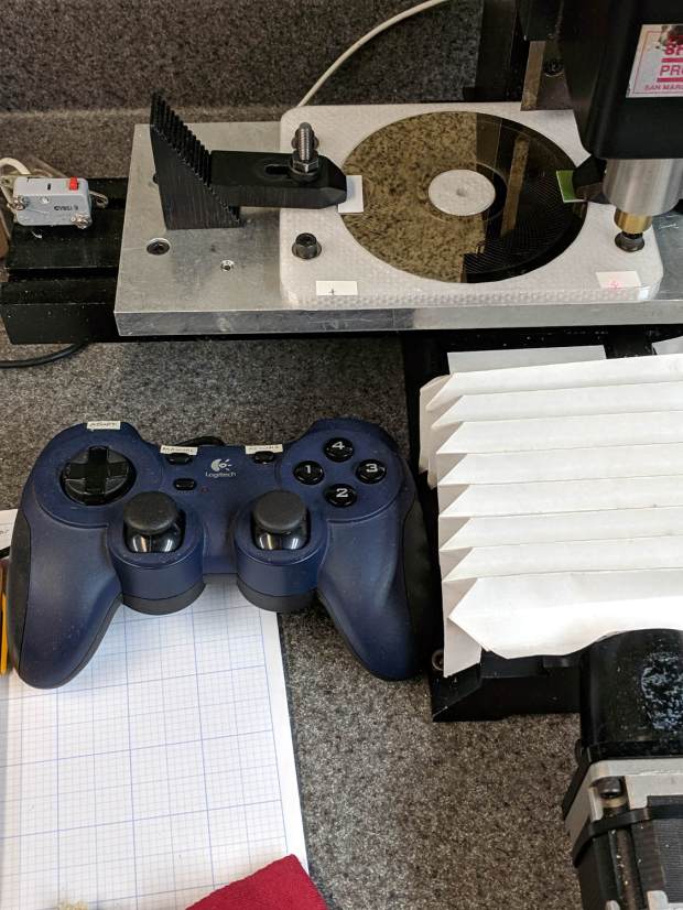
    Up to this point, the Sherline has been drilling 3.5 inch hard drive platters to serve as as reflecting bases for the vacuum tubes:

    LinuxCNC - Sherline Mill - Logitech Gamepad
    LinuxCNC – Sherline Mill – Logitech Gamepad

    The CNC 3018-Pro has a work envelope large enough for CD / DVD platters, so I mashed the Sherline fixture with dimensions from the vacuum tube code, added the 3018’s T-slot spacing, and conjured a pair of fixtures for a pair of machines.

    Because I expect to practice on scrap CDs and DVDs for a while:

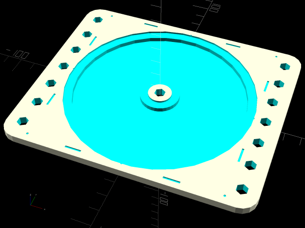
    Platter Fixtures - CD on 3018
    Platter Fixtures – CD on 3018

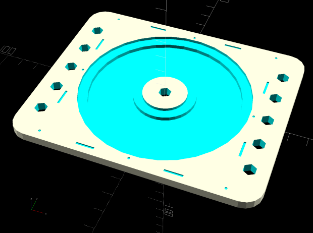
    And a 3.5 inch hard drive platter version:

    Platter Fixtures - hard drive platter on 3018
    Platter Fixtures – hard drive platter on 3018

    The holes sit at half the 3018’s T-slot spacing (45 mm / 2), so you can nudge the fixtures to the front or rear, as you prefer.

    The alignment dots & slots should help touch off the XY coordinate system on the Sherline, although it can’t reach all of a CD. Using bCNC’s video alignment on the hub hole will be much easier on the 3018.

    After fiddling around with the 3018 for a while, however, the CD fixture doesn’t have many advantages over simply taping the disc to a flat platen. Obviously, you’d want a sacrificial layer for drilling, but it’s not clear the OEM motor / ER11 chuck would be up to that task.

    The OpenSCAD source code as a GitHub Gist:

    // Machining fixtures for CD and hard drive platters
    // Ed Nisley KE4ZNU February … September 2016
    // 2019-08 split from tube base models
    PlatterName = "CD"; // [3.5inch,CD]
    CNCName = "3018"; // [3018,Sherline]
    PlateThick = 5.0; // [5.0,10.0,15.0]
    RecessDepth = 4.0; // [0.0,2.0,4.0]
    //- Extrusion parameters must match reality!
    /* [Hidden] */
    ThreadThick = 0.25;
    ThreadWidth = 0.40;
    HoleWindage = 0.2;
    Protrusion = 0.1; // make holes end cleanly
    inch = 25.4;
    function IntegerMultiple(Size,Unit) = Unit * ceil(Size / Unit);
    module PolyCyl(Dia,Height,ForceSides=0) { // based on nophead's polyholes
    Sides = (ForceSides != 0) ? ForceSides : (ceil(Dia) + 2);
    FixDia = Dia / cos(180/Sides);
    cylinder(d=(FixDia + HoleWindage),h=Height,$fn=Sides);
    }
    ID = 0;
    OD = 1;
    LENGTH = 2;
    //———————-
    // Dimensions
    P_NAME = 0; // platter name
    P_ID = 1; // … inner diameter
    P_OD = 2; // … outer diameter
    P_THICK = 3; // … thickness
    PlatterData = [
    ["3.5inch", 25.0, 95.0, 1.75],
    ["CD", 15.0, 120.0, 1.20],
    ];
    PlatterSides = 3*4*5; // polygon approximation
    B_NAME = 0; // machine name
    B_OC = 1; // … platform screw OC, use small integer for slot
    B_STUD = 2; // … screw OD clearance
    BaseData = [
    ["3018", [5.0, 45.0], 6.0], // slots along X axis
    ["Sherline", [1.16*inch,1.16*inch], 5.0], // tooling plate
    ];
    //———————-
    // Drilling fixture for disk platters
    module PlatterFixture(Disk,Machine) {
    PI = search([Disk],PlatterData,1,0)[P_NAME]; // get platter index
    echo(str("Platter: ",Disk));
    Platter = [PlatterData[PI][P_ID],
    PlatterData[PI][P_OD],
    PlatterData[PI][P_THICK]];
    BI = search([Machine],BaseData,1,0)[B_NAME]; // get base index
    echo(str("Machine: ",Machine));
    AlignOC = IntegerMultiple(Platter[OD],10);
    echo(str("Align OC: ",AlignOC));
    AlignSlot = [3*ThreadWidth,10.0,3*ThreadThick];
    StudClear = BaseData[BI][B_STUD]; // … clearance
    StudOC = [IntegerMultiple(AlignOC + 2*StudClear,BaseData[BI][B_OC].x), // … screw spacing
    BaseData[BI][B_OC].y];
    echo(str("Stud spacing: ",StudOC));
    NumStuds = [2,1 + 2*floor(Platter[OD] / StudOC.y)]; // holes only along ±X edges
    echo(str("Stud holes: ",NumStuds));
    BasePlate = [(20 + StudOC.x*ceil(Platter[OD] / StudOC.x)),
    (10 + AlignOC),
    PlateThick];
    echo(str("Plate: ",BasePlate));
    PlateRound = 10.0; // corner radius
    difference() {
    hull() // basic plate shape
    for (i=[-1,1], j=[-1,1])
    translate([i*(BasePlate.x/2 – PlateRound),j*(BasePlate.y/2 – PlateRound),0])
    cylinder(r=PlateRound,h=BasePlate.z,$fn=4*4);
    for (i=[-1,0,1], j=[-1,0,1]) // origin pips
    translate([i*AlignOC/2,j*AlignOC/2,BasePlate.z – 2*ThreadThick])
    cylinder(d=4*ThreadWidth,h=1,$fn=6);
    for (i=[-1,1], j=[-1,1]) { // alignment slots
    translate([i*(AlignOC + AlignSlot.x)/2,
    j*Platter[OD]/4,
    (BasePlate.z – AlignSlot.z/2 + Protrusion/2)])
    cube(AlignSlot + [0,0,Protrusion],center=true);
    translate([i*Platter[OD]/4,
    j*(AlignOC + AlignSlot.x)/2,
    (BasePlate.z – AlignSlot.z/2 + Protrusion/2)])
    rotate(90)
    cube(AlignSlot + [0,0,Protrusion],center=true);
    }
    for (i=[-1,1], j=[-floor(NumStuds.y/2):floor(NumStuds.y/2)]) // mounting stud holes
    translate([i*StudOC.x/2,j*StudOC.y/2,-Protrusion])
    rotate(180/6)
    PolyCyl(StudClear,BasePlate.z + 2*Protrusion,6);
    translate([0,0,-Protrusion]) // center clamp hole
    rotate(180/6)
    PolyCyl(StudClear,BasePlate.z + 2*Protrusion,6);
    translate([0,0,BasePlate.z – Platter[LENGTH]]) // disk locating recess
    rotate(180/PlatterSides)
    linear_extrude(height=(Platter[LENGTH] + Protrusion),convexity=2)
    difference() {
    circle(d=(Platter[OD] + HoleWindage),$fn=PlatterSides);
    circle(d=Platter[ID] – HoleWindage,$fn=PlatterSides);
    }
    translate([0,0,BasePlate.z – RecessDepth]) // drilling recess
    rotate(180/PlatterSides)
    linear_extrude(height=(RecessDepth + Protrusion),convexity=2)
    difference() {
    circle(d=(Platter[OD] – 10),$fn=PlatterSides);
    circle(d=(Platter[ID] + 10),$fn=PlatterSides);
    }
    }
    }
    //———————-
    // Build it
    PlatterFixture(PlatterName,CNCName);