Ed Nisley's Blog: Shop notes, electronics, firmware, machinery, 3D printing, laser cuttery, and curiosities. Contents: 100% human thinking, 0% AI slop.
Tag: Improvements
Making the world a better place, one piece at a time
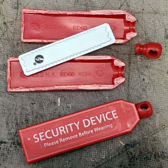
Having worn my work glove collection to exhaustion, the fanciest two pairs in a new selection came with elaborate security tags:
Elaborate Security Tag dissection
Finding a standard tag inside inside the fancy shell shouldn’t come as any surprise, but I’m surprised the retail loss ratio for a pair of $20 gloves can support that much hardware.
I went through the self-checkout area and didn’t do anything special, so either those lanes don’t have tag scanners or the tags are security theater.
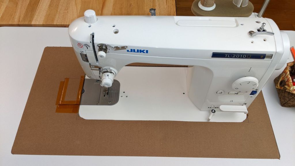
Mary’s new sewing table just arrived, but the laser-cut acrylic insert fitting around her Juki sewing machine is still a month or two away. Until then, a simple cardboard replacement must suffice to fill the gap:
Juki temporary table insert
The rectangle just to the left of the needle is a hatch for bobbin changes. Sheer faith and an interference fit between layers of Kapton tape holds it in place with surprising force.
I wanted to tape the cardboard edges to the machine and the table to smooth out the transitions, but her Supreme Slider slippery sheet may solve the problem without adhesives:
Juki temporary table insert – Super Slider
The “insert” is a 1/4 inch thick double-layer corrugated cardboard sheet, utility-knifed from a huge box. She layers cardboard under the wood chips in her Vassar Farms garden paths to discourage the weeds; this seemed like a perfectly reasonable diversion.
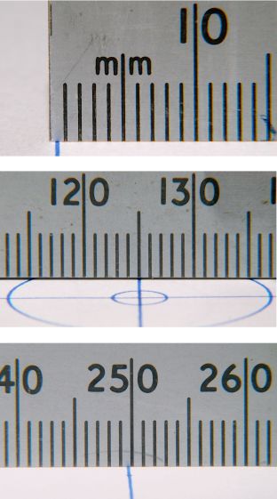
Plotting the backlash / calibration target on both the CNC-3018XL and the MPCNC quickly showed, contrary to what I expected, the MPCNC was dead-on accurate, albeit with some wobbulation and a trace of backlash:
MPCNC – Backlash test – detail
Although it looks ug-u-lee, the (lower speed) drag knife cuts come out nice and, because the entry and exit moves match the main cut, the minimal backlash wasn’t a problem.
Turns out only the X axis on the 3018XL had a problem:
Cal Target – 400 step-mm – merged
Apparently the longer leadscrew I installed as part of the “XL” conversion has a small thread pitch error: about 1 mm short in every 250 mm of travel. I don’t have any (definite, non-handwavy) method to measure the pitch directly, other than by running the follower nut and measuring the results, but it’s consistently short.
Quite some time ago (after blowing up the OEM controller board), I set up the Protoneer CNC board in 1:8 microstep mode, making the GRBL $100 setting a nice, round 400 step/mm for a two-start leadscrew with 2 mm pitch and 4 mm lead:
After a few more measurements suggesting the leadscrew actually traveled 249.2 mm, the correct value will be:
401.28 step/mm = 400 step/mm × 250 mm / 249.2 mm
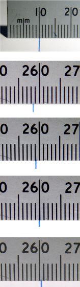
To verify I understood the problem and solution, I set $100 to a few integer values around the goal:
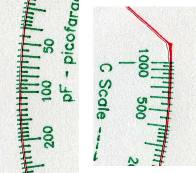
Cal Target – stacked – 399-402 step-mm
The top image shows the leftmost line at the 10 mm mark on the scale, because it’s easier for me to match the ink line with an engraved line, rather than the non-line at the end of the ruler.
The other images show the results for $100 set to 399, 400, 401, and 402 step/mm, respectively. The results last two results bracket the desired 250 mm outcome, with 401 step/mm being Close Enough™. GRBL accepts a floating point step/mm value, so I set $100 to 401.28, but I was unable to convince myself the result came out consistently different than 401.00.
Plotting both the tick marks (green) and the knife path (red) on the 3018XL, then cutting the bare paper on the MPCNC, showed the two machines now agree on where the knife should fall. The outer end of the tick marks extends 1 mm beyond the cut line to ensure small misalignments do not produce an obvious white gap around the edge of the deck.
The Y axis continues to match:
Tek CC – 2022-02-14 – Y detail
And now the X axis looks just as good:
Tek CC – 2022-02-14 – X detail
The drag knife corners are rounded, as you’d expect. The cut seems slightly offset from a small origin touch-off error, but the scales now match.
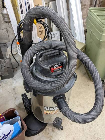
Shortly after acquiring the Greatest ShopVac, I zip-tied half a foot of cardboard tube to the handle to corral the nozzle and keep the ungainly hose from sprawling across the floor. While disembowling the Ottlite into a mini-lathe light, the plastic trim joining the baseplate to the vertical tube cried out to become a nozzle caddy:
ShopVac Nozzle Caddy – front view
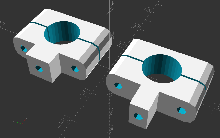
It was exactly the right size and shape (by my admittedly slack standards) to hold the nozzle, plus being destined for the trash, so all it needed was a pair of clamp brackets conjured from the vasty digital deep:
ShopVac Nozzle Caddy – solid model
The bosses fit into a tapered slot along what was the rear side, with a pair of 4 mm holes at each end for screws into threaded brass inserts epoxied into the brackets:
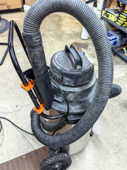
ShopVac Nozzle Caddy – clamps mounted
They obviously descend from the many clamp mounts I’ve made for everything from garden hoses to bike running lights. A pair of 4 mm SHCS squish the clamp around the handle, with a strip of electrical tape improving plastic-to-metal griptivity:
ShopVac Nozzle Caddy – side view
The clearance just barely allows a nylock nut atop a washer and you’ll want to trim those 40 mm screws to an exact fit, but it came out pretty well.
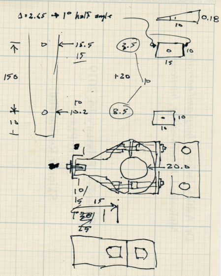
The original dimension doodle with some modeling ideas that didn’t survive more thinking:
ShopVac Nozzle Caddy – Dimension Doodle 1
A more detailed doodle with brass inserts instead of the nylock nuts and an aluminum spreader plate that was obviously not necessary:
ShopVac Nozzle Caddy – Dimension Doodle 2
In retrospect, the inserts would make more sense.
The angle doodles convinced me not to bother modeling either the slot’s taper along its length or its mold draft.
Kinda looks like it grew there and makes one wonder why they don’t include a caddy as a standard option.
This file contains hidden or bidirectional Unicode text that may be interpreted or compiled differently than what appears below. To review, open the file in an editor that reveals hidden Unicode characters.
Learn more about bidirectional Unicode characters
It’s one of the few Underwriter’s Knots I’ve ever seen in the wild. Many recent (i.e., built in the last half-century) lamps pass the cords through a plastic clamp or depend on simple bushings, with some just ignoring the problem.
This anonymous lamp sports the usual Made in China sticker, but also features a genuine-looking UL sticker complete with elaborate holograms, so it may well have been sold by a reputable company. IIRC, it came from a trash can in a Vassar College hallway, back when in-person meetings were a thing; perhaps Vassar required known-good electrical hardware.
A few months of inactivity left the CNC-3018XL table parked in its homed position where the gentle-but-inexorable pressure of the switch lever displaced the foam holding the plastic actuator tab on the X-axis bearing enough that it would no longer operate reliably:
3018 CNC – Y axis endstop
Putting foam tape in a highly leveraged position produces the same poor results as in finance.
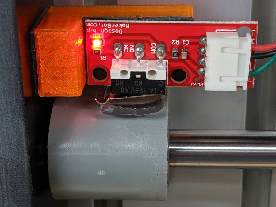
The fix requires reorienting the switch so a solid block on the bearing can push directly on the actuator lever:
CNC-3018 X Home Switch – bottom view
The block must curve around the bearing to give the tape enough surface area for a good grip:
CNC-3018 X Home Switch – oblique view
The solid model for the new X-axis mount looks about like you’d expect:
CNC-3018 X Home Switch Mount – solid model
I increased the home switch pulloff to 2 mm, although it’s not clear that will make any difference in the current orientation.
This file contains hidden or bidirectional Unicode text that may be interpreted or compiled differently than what appears below. To review, open the file in an editor that reveals hidden Unicode characters.
Learn more about bidirectional Unicode characters