After extending the CNC 3018-Pro platform to 340 mm along the Y axis, I tweaked the Spirograph demo to work with 8-1/2×11 paper:
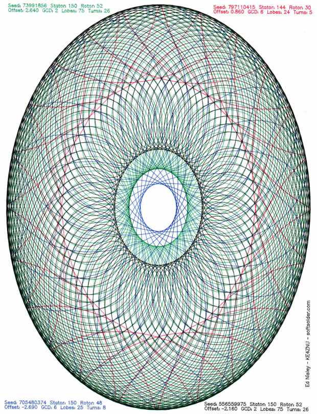
Yeah, a Portrait mode plot kinda squinches the annotations into the corners.
Rotating the coordinates to put the X axis along the length of the new platform is, of course, a simple matter of mathematics, but it’s just a whole lot easier to rearrange the hardware to make the answer come out right without fancy reprogramming.
The first step is to affix an MBI-style endstop switch to the left end of the gantry upright:
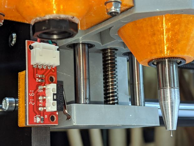
The gantry carriage sits at the 1 mm pulloff position, with the switch lever just kissing the (fixed) lower carriage plate. As before, good double-sticky foam tape holds everything in place.
The probe camera hovers just over the switch and the Pilot V5RT pen holder is ready for action.
Shut down the Raspberry Pi and turn off the power!
At the CAMtool V3.3 board:
- Swap the X and Y motor cables
- Move the former Y endstop switch to the X axis input
- Plug the new endstop switch into the Y axis input, routing its cable across the top of the gantry
- Abandon the former X axis switch and its cable in place
Modify the GRBL configuration:
$3=4– +Y home @ gantry left, +X home @ frame front$130=338– X axis travel along new frame$131=299– Y axis travel across gantry
Tweak the bCNC config similarly, if that’s what you’re into.
Verify the new home position!
I reset the G54 coordinate system to put XY = 0 at the (new!) center of the platform, redefined G28 as the “park” position at the (new!) home pulloff position, and set G30 as the “tool change” position at the -X -Y (front right) corner of the platform, with bCNC icons to simplify moving to those points.
And then It Just Worked™:
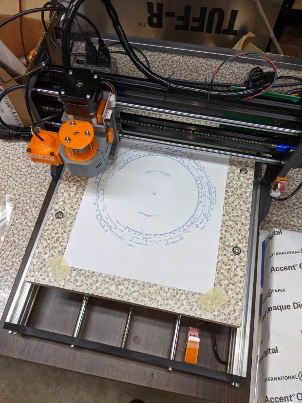
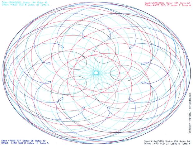
The Spirograph patterns definitely look better in landscape mode:
I eventually turned the whole machine 90° clockwise to align the axes with the monitor, because I couldn’t handle having the X axis move front-to-back on the table and left-to-right on the screen.
