Ed Nisley's Blog: Shop notes, electronics, firmware, machinery, 3D printing, laser cuttery, and curiosities. Contents: 100% human thinking, 0% AI slop.
Tag: Improvements
Making the world a better place, one piece at a time
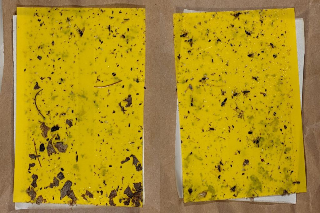
Mary decided the second round of sticky traps had collected enough Onion Maggot Flies (and other detritus) to warrant replacement, so this season will have three sets of cards.
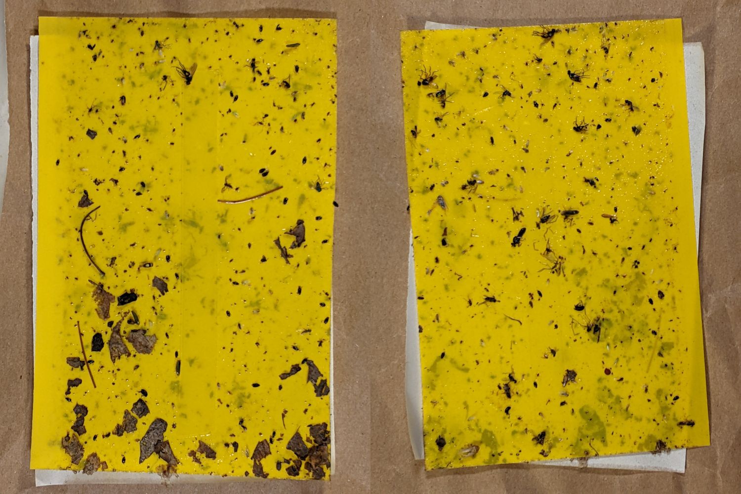
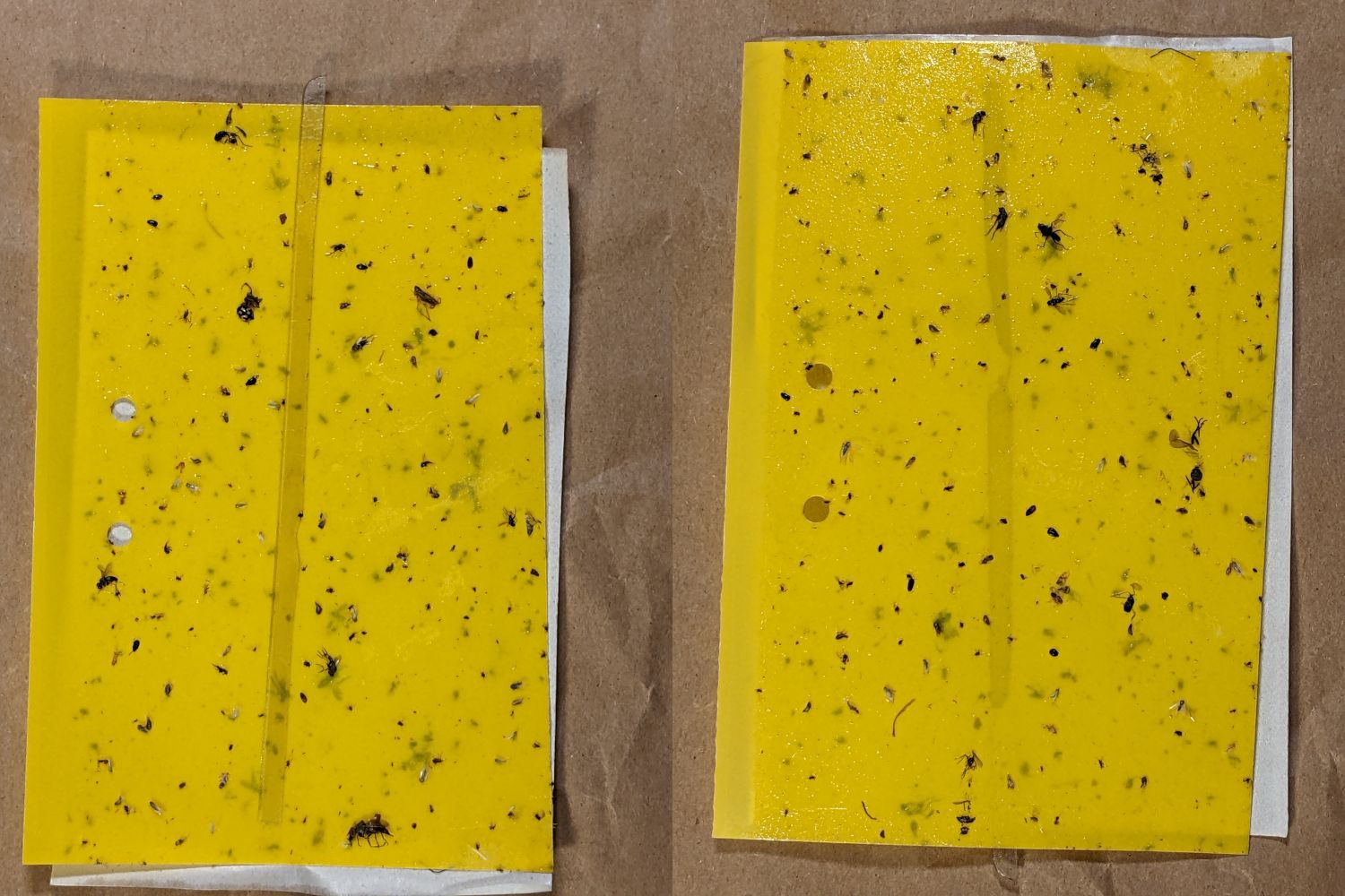
The two sides of each card after about a month in the garden:
VCCG Onion Card A – 2022-07-17
VCCG Onion Card B – 2022-07-17
VCCG Onion Card C – 2022-07-17
VCCG Onion Card D – 2022-07-17
VCCG Onion Card E – 2022-07-17
VCCG Onion Card F – 2022-07-17
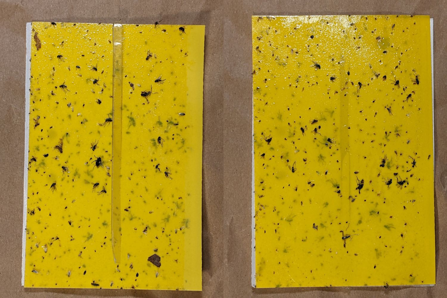
There are many flies that look (to me) like Onion Maggot Flies, in contrast with the first round of cards which had far fewer flies after about six weeks in the bed.
One of the frames screwed to a fence post suffered a non-fatal mishap, so I made and deployed a seventh trap. We’re pretty sure the garden has enough flies to go around.
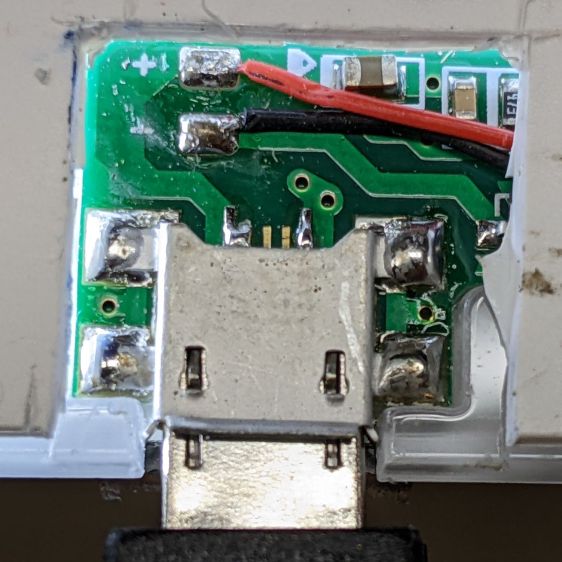
Unfortunately, reinforcing the USB Micro-B jack on the side of the LitUp LED Light Pad only delayed the inevitable: the light became erratic even without the slightest touch. The pad consists of three acrylic sheets glued together around the entire perimeter, so there’s no way to get access to the no-user-serviceable-parts within. Apparently, you’re supposed to just throw it out.
On the other paw, it’s already dead, so there’s nothing to lose:
LitUp LED Light Pad – failed USB jack
A little deft razor knife work chopped through the rear sheet without doing any (more) damage to the PCB within. The LEDs can still be convinced to light, but the USB jack is definitely wrecked.
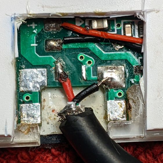
Applying some ChipQuik let me extract the jack without (too much) more damage. Rather than replace it, I just soldered a pigtail USB cable to the obvious PCB pads:
LitUp LED Light Pad – direct power wiring
If I’d noticed that little solder ball, I’d have removed it before filling the cavity with hot melt glue and squishing the cut-out piece of white acrylic in place.
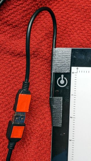
A little black duct tape should keep the wiring stable enough for the foreseeable future:
LitUp LED Light Pad – redirected cable
That was another (relatively) easy zero-dollar repair that should not be necessary.
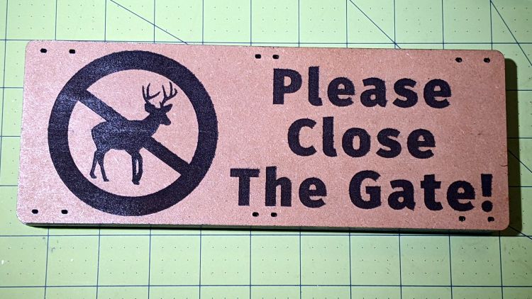
It seems two months of sunlight will fade laser charred MDF down to its original state:
Please Close The Gate – unpainted faded
That’s through a thick layer of indoor urethane sealant slathered over MDF without any surface prep. Obviously, not removing the char had no effect on the outcome. On the upside, the urethane did a great job of protecting the MDF from rainfall.
So. Back to the shop.
Lacking wider masking tape, two strips of tape laid along a cut-to-suit slab of fresh MDF will serve as a paint mask:
Please Close The Gate – masked engraving
Belatedly I Learned: cut the tape close to the edge, then fold it under so the autofocus pen can’t possibly snag it en passant.
Shoot the entire surface with a couple of black enamel rattlecan coats:
Please Close The Gate – masked paint
Yes, the engraved areas look reddish, most likely due to another complete lack of surface prep. Perhaps brushing / vacuuming / washing would remove some of the char, but let’s see how it behaves with no further attention.
Peel the tape, weed the letters / antlers, slather on a coat of urethane, and it looks downright bold:
Please Close The Gate – sealed
Of course, if those two tape strips don’t exactly abut, the paint produces a nasty line:
Please Close The Gate – mask gap
Should you overlap the strips a wee bit to ensure cleanliness, the engraved surface will then have a noticeable (in person, anyhow) discontinuity due to the laser losing energy in two tape layers, which wouldn’t matter in this application. We defined the few paint lines as Good Enough™ for the purpose; a strip of absurdly wide masking tape is now on hand in anticipation of future need.
Burnishing the tape might have prevented paint bleed around the engraved areas:
Please Close The Gate – paint creep
But, given that I was painting raw / unfinished MDF with an unsmooth surface, burnishing probably wouldn’t produce a significantly better outcome.
By popular request, the new signs sit a few grids lower on the gates:
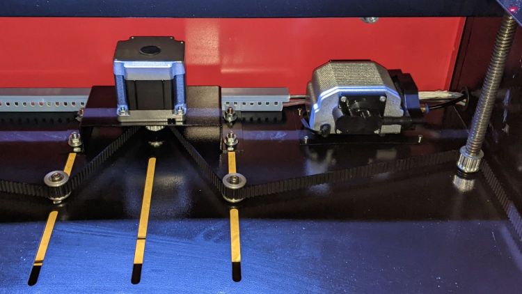
The air assist pump sits in the right rear of the OMTech laser’s main compartment:
OMTech 60W laser – Z motor – air pump
Where it is, of course, exposed to all the usual dust / fragments / fumes / smoke generated by laser cutting & engraving, enhanced by my attention to getting good air flow over the platform. The picture shows the base plate in as-delivered condition, which it will never resemble ever again.
The problem: any crud in the air can clog the pump or contaminate the laser focus lens.
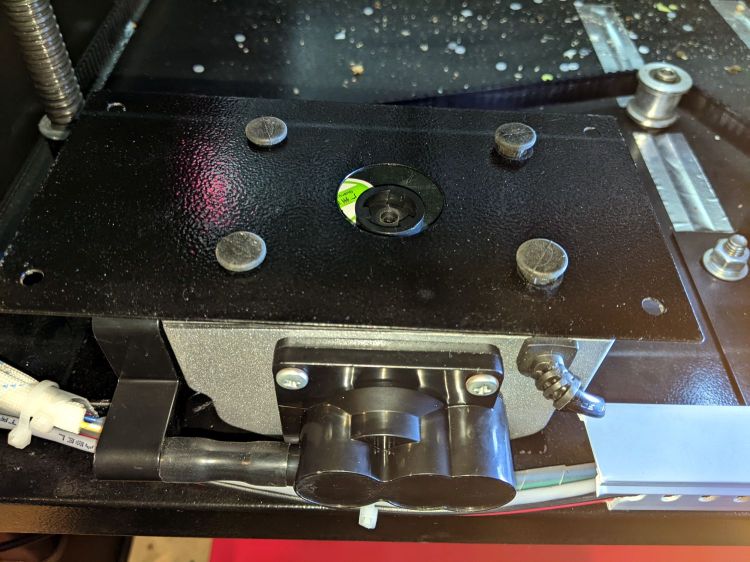
Four screws into threaded holes hold the pump to the base plate, secured with jam nuts on the outside.
The air inlet is a round fitting centered on the bottom of the pump housing:
OMTech 60 W Laser Air Assist – pump inlet
You’ll note the out-of-focus crud scattered on the base plate.
The general idea is to drill a hole through the base plate, put a snorkel on the inlet, and have it inhale fresh, relatively clean, basement air from outside the cabinet. The trick will be not touching the base plate with anything solid, because the pump vibrates like crazy; its four squishy standoffs do a great job of isolating the tremors from the base screwed to the laser cabinet.
Having a few other things going on at the moment, I just laid two generous wads of cheesecloth where they can filter the bigger chunks out of the air stream:
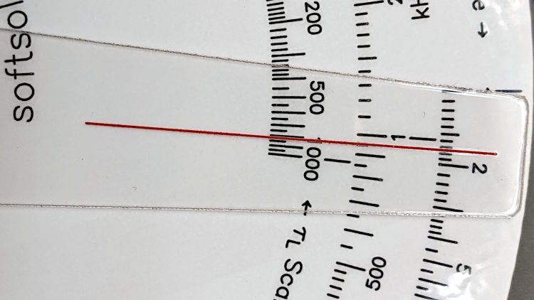
OMTech 60 W Laser Air Assist – cheesecloth filter installed
The air flow meter says the pump still delivers 12 l/m to the nozzle, so the cheesecloth has no effect compared to four or five feet of 4 mm ID tubing.
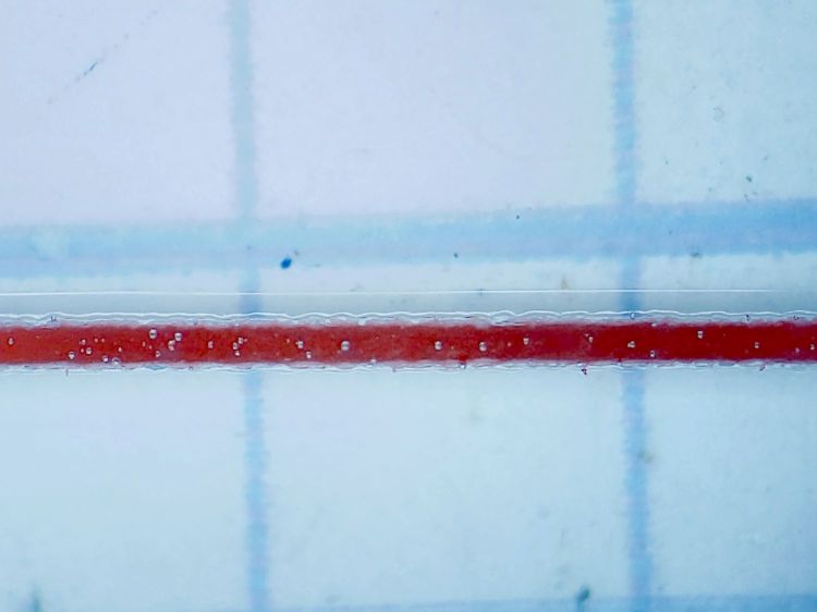
A doodle summarizes the inlet fitting dimensions:
OMTech 60 W Laser Air Assist – pump inlet fitting measurements
That looks like a 3D printed disk with a snout for a short air hose should do the trick, with a thin gasket sealing the disk to the fitting.
A rare trip to the Poughkeepsie Railroad Station provided an opportunity to check out the LED bulbs in the chandeliers:
The 108 bulbs had only one deader (lower left in chandelier C).
I have no way of knowing if they’re the same bulbs from six years ago, but the accumulation of bugs / dust / crud inside the (what I would expect to be) sealed envelopes suggests they’ve been hanging there for quite a while:
Pok RR Station – Chandelier B – detail
The dark cruciform patches might come from failed LED chip strings, although the bulbs all had the same eyeballometric brightness. The patches all seem to have a hard lower edge, so we may be seeing shadows from dust accumulating atop the chips on the PCB.
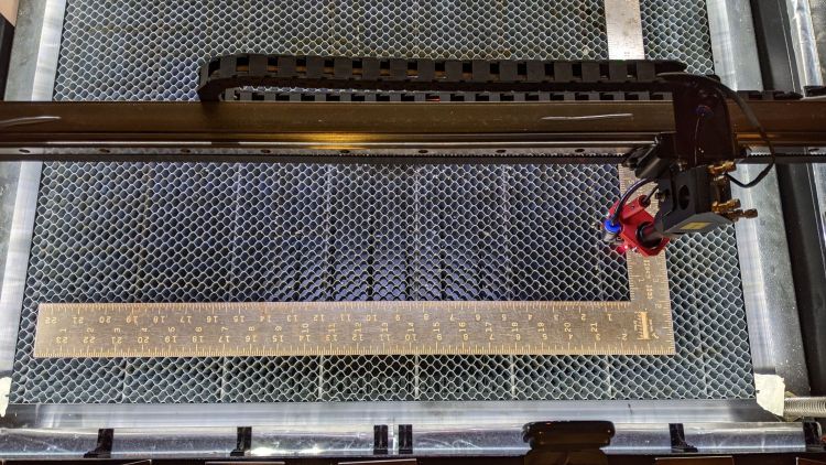
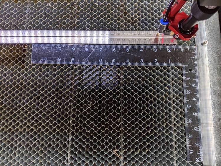
After tweaking the OMTech laser’s axis scale calibration, it seemed like a good idea to see whether the axes run perpendicular to each other:
OMTech Axis Cal – framing square
A carpenter’s framing square isn’t the most precise instrument, but the pair in my collection agree on their right-angularity to within my ability to measure the difference.
Aligning the short arm with the Y axis showed the X axis was off by 1.2 mm in 21 inches = 530 mm, an angle of 0.13°, which is just about as good as it’s ever going to be.
The honeycomb frame is definitely not a precisely aligned unit, but the front edge is parallel to the X axis within an astonishing 0.03°, measured along the rear edge of the long arm pushed against the front of the frame. The aluminum frame has a distinct outward bow in the middle averaged out by the long arm.
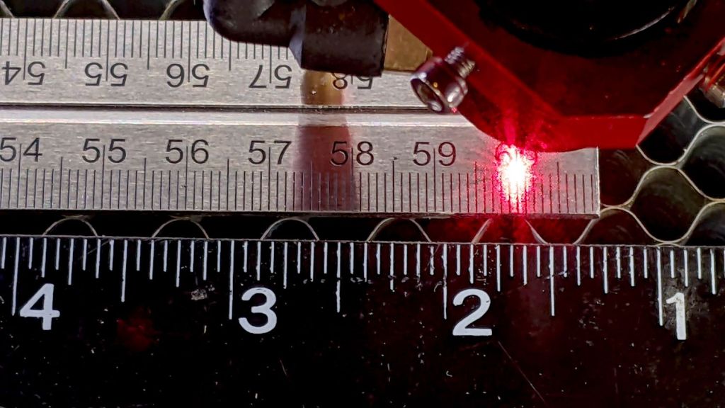
Unfortunately, the honeycomb frame on the right side is nowhere near that nice. While I had the long scale aligned with the X axis travel, I sleazed a smaller square up against it:
OMTech Axis Cal – honeycomb frame misalignment
It’s as bad as it looks:
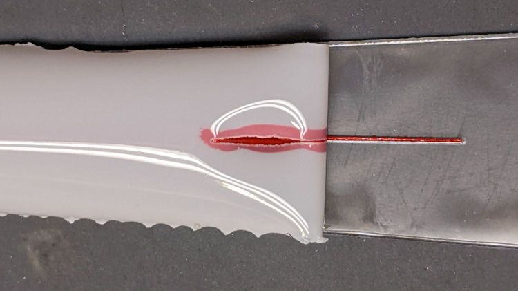
OMTech Axis Cal – honeycomb frame vs axis travel – detail
The scale departs from the black square’s arm by 4 mm over 260 mm, for a 0.88° misalignment.
I think the honeycomb frame is, at best, a parallelogram (and likely a trapezoid), and each side is also bowed by a few millimeters along its length, so any misalignment will depend on where you stand and which way you look.
In all fairness, it was never intended as an alignment fixture and nobody really cares about angular misalignment as long as the puppy portrait comes out pretty much in the middle of the coaster.
Angular Alignment meme
Yes, yes I am.
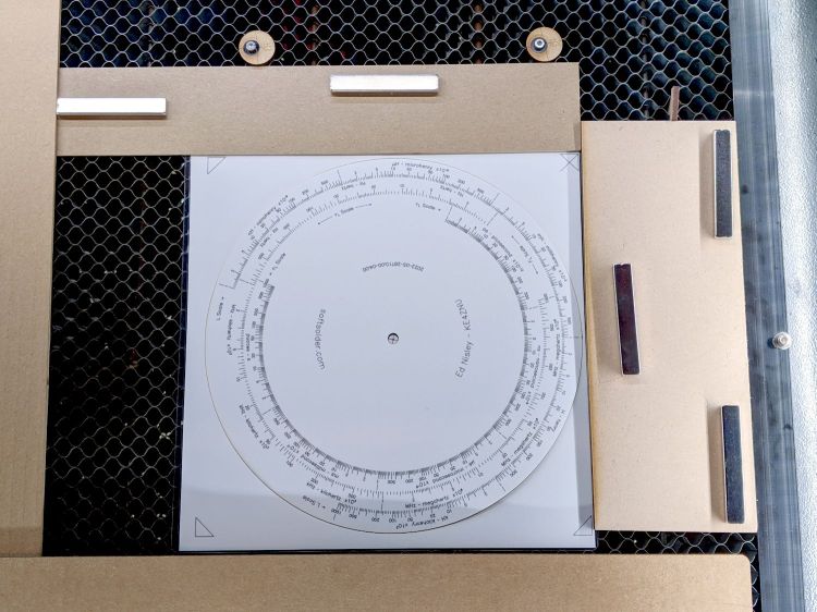
It’s easy enough to make an alignment fixture:
OMTech Axis Cal – honeycomb frame angle fixture
The cut along the left edge is, by definition, parallel to the Y axis, so the left edge of the larger slice serves to align flat things to be cut and hold them in place:
Laser cutter deck fixture
The upper sheet (a simple chipboard rectangle) sits perpendicular (set with the short square) to the edge, held to the honeycomb with magnets, and kept in alignment with two adjustable stops snugged against it. A few smaller magnets can hold the sheet flat against the honeycomb as needed.
The sliver cut off the MDF is 7.85 mm at the top and 9.70 mm at the bottom, for an angle of 0.53° over its 210 mm length, a bit less than the angle measured above. It now lives in the tooling pile against future need.