A Circuit Cellar reader asked for a better explanation of the parasitic capacitors inside a quartz crystal can than I provided in my April 2017 Circuit Cellar column. Here’s the schematic, with values for a 32 kHz tuning fork resonator and the original caption:

I wrote this about the caps:
The value of C0 in the model’s middle branch corresponds to the capacitance between the electrodes plated onto the quartz. The 3.57954 MHz crystal in the title photo, with two silver electrodes deposited on a flat insulating disk, closely resembles an ordinary capacitor. You can measure a crystal’s C0 using a capacitance meter.
However, each of those electrodes also has a capacitance to the resonator’s metal case. The top branch of the model shows two capacitors in series, with Cpar representing half the total parasitic capacitance measured between both leads and the case. Grounding the case, represented by the conductor between the capacitors, by soldering it to the ground plane of an RF circuit eliminates any signal transfer through those capacitors. They will appear as shunt capacitors between the pins and ground; in critical applications, you must add their capacitance to the external load capacitors.
And this about the measurement technique, using a fixture on my AADE LC meter:
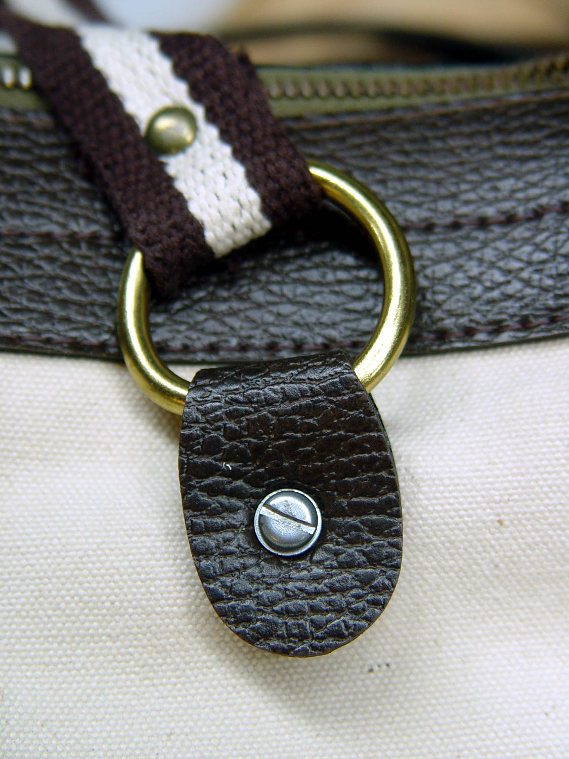
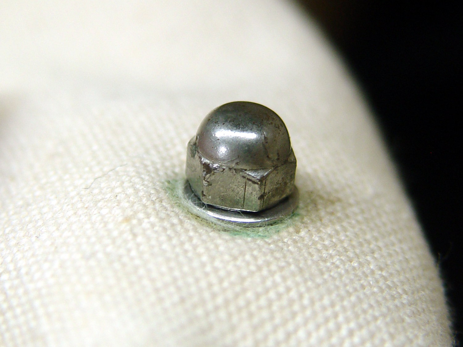
With the resonator case captured under the clip on the far right and both its leads held by the clip to the upper left, the meter measures Cpar, the lead-to-case parasitic capacitance. The meter will display twice the value of each parasitic capacitor, at least to a good approximation, because they are in parallel. The five resonators averaged 0.45 pF, with each lead having about 0.25 pF of capacitance to the case. Obviously, measuring half a picofarad requires careful zeroing and a stable fixture: a not-quite-tight banana jack nut caused baffling errors during my first few measurements.
With the resonator repositioned as shown in Photo 2, with one lead under each clip, the meter measures C0, the lead-to-lead capacitance. After careful zeroing, the resonators averaged 0.85 pF.
Although the parasitic lead-to-case capacitors are in parallel with C0, their equivalent capacitance is only Cpar/4 = 0.1 pF. That’s close enough to the measurement error for C0, so I ignored it by rounding C0 upward.
He quite correctly pointed out:
With both leads connected together on one side, then that essentially constitutes a single electrical element inside the case. And with the case being a single element, this configuration in the test fixture seems like a single capacitor with one lead being the case and the other lead being the pins, with a vacuum dielectric.
I would think the meter would display the total capacitance rather than twice the value … It makes sense to me to later say Cpar/2 when the leads are not connected together.
Here’s my second pass at the problem:
… the two-capacitor model comes from the common-case condition, where each lead displays a (nominally equal) parasitic capacitance to the case, because the crystal mounting is reasonably symmetric inside the can. It’s easiest to measure the total capacitance with the leads shorted together, because it’s in the low pF range, then divide by two to get the value of each lead-to-case cap.
[…]
For “real” RF circuits with larger (HC-49 -ish) crystals in parallel-resonance mode, you ground the case and subtract the parasitic capacitance at each lead from the external load capacitors. That’s the usual situation for microprocessor clock oscillators: the crystal sits across the clock amplifier pins, with two more-or-less equal caps from the pins to ground. You should subtract the internal parasitic caps from the clock’s specified load caps, but in practice the values are so small and the cap tolerance so large that it mostly doesn’t matter.
[…]
Un-grounding the case puts those two parasitic caps in series, just as with two discrete caps, so the lead-to-lead capacitance is (or should be!) half of each: 1/4 of the both-leads-to-case value.
Re-reading yet again says I glossed over the effect of having C0 in parallel with the Cpar/2 caps, but methinks dragging those complications into the model benefits only the theoreticians among us (or those working very close to the edge of the possible).
To make it worse, I also botched the QEX reference, which should be Jan/Feb 2016, not 2017. Verily, having a column go read-only makes the errors jump right off the page. [sigh]
At least I can point to this and amend as needed.