I let the DDS cool down overnight, turned it on, and recorded the frequency offset as a function of temperature as it heated up again:
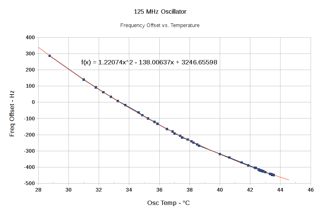
The reduced spacing between the points as the temperature increases shows how fast the oscillator heats up. I zero-beat the 10 MHz output, scribbled the temperature, noted the offset, and iterated as fast as I could. The clump of data over on the right end comes from the previous session with essentially stable temperatures.
I only had to throw out two data points to get such a beautiful fit; the gaps should be obvious.
The fit seems fine from room (well, basement) ambient up to hotter than you’d really like to treat the DDS, so using the quadratic equation should allow on-the-fly temperature compensation. Assuming, of course, the equation matches some version of reality close to the one prevailing in the Basement Laboratory, which remains to be seen.
In truth, it probably doesn’t, because the temperature was changing so rapidly the observations all run a bit behind reality. You’d want a temperature-controlled environment around the PCB to let the oscillator stabilize after each increment, then take the measurements. I am so not going to go there.
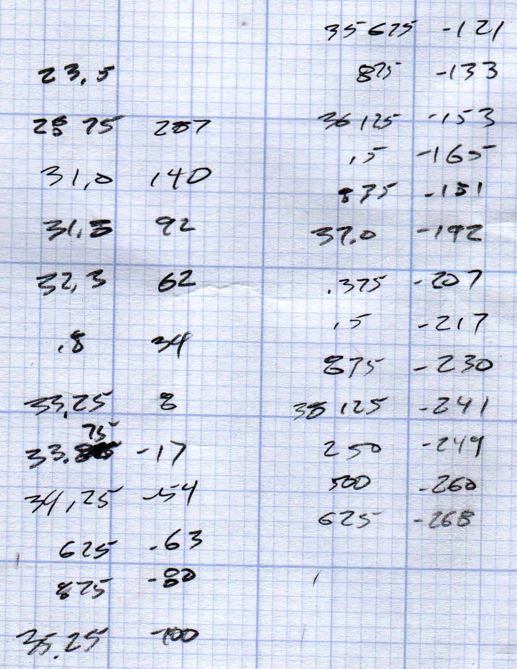
The original data:

Comments
One response to “AD9850 DDS Module: 125 MHz Oscillator vs. Temperature, Quadratic Edition”
[…] trust the AD9850 readout, because I just finished zero-beating it against the GPS-locked 10 MHz frequency reference: it’s dead on. The scope’s […]