Ed Nisley's Blog: Shop notes, electronics, firmware, machinery, 3D printing, laser cuttery, and curiosities. Contents: 100% human thinking, 0% AI slop.
Tag: Improvements
Making the world a better place, one piece at a time
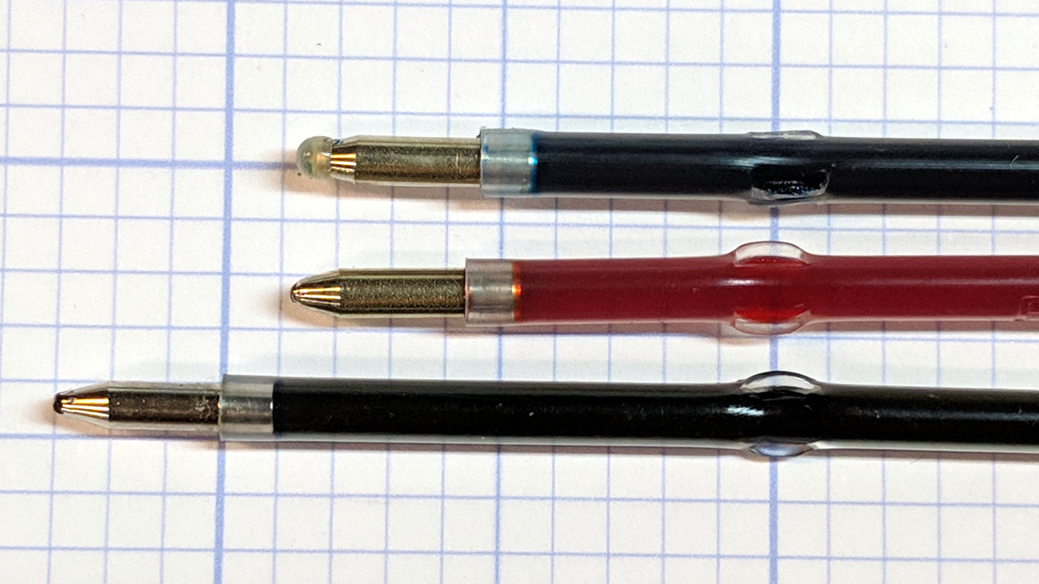
The three collet pen holders I got a while ago came with ink cartridges:
Collet pen holder
So I bought three bucks worth of a dozen pens to get pretty colors, whereupon I discovered they didn’t fit into the collet. Turns out the locating flanges aren’t in the same place along the cartridges:
The flanges on the top cartridge have been shaved down perilously close to the ink, but it now fits into the collet.
Bonus: a dozen fairly stiff springs that are sure to come in handy for something!
After nearly four years of dangling a bare millimeter above the nozzle, the lever on the relocated Z-Axis switch finally snagged a stray thread and got bent out of shape. I un-bent it, but finally decided it was time to get more air between the nozzle and the switch actuator.
Prying the ends outward with a thumbnail releases a pair of snaps and the cover pops off to reveal the innards:
M2 Z-Axis – microswitch interior
The spring-loaded innards will launch themselves into the far corners of your shop, so be gentle as you slide the lever out and reinstall the side plate with a pair of clicks.
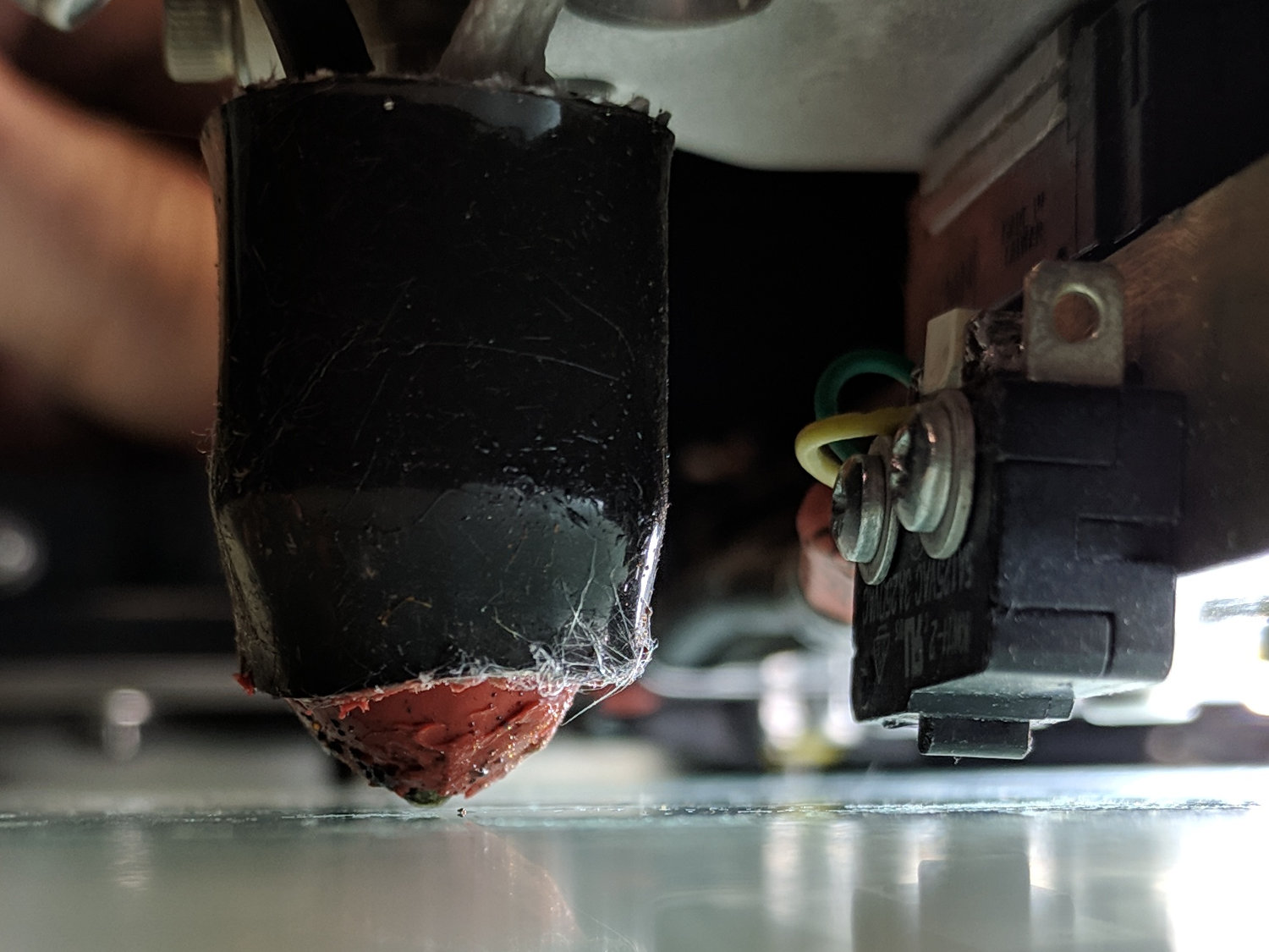
I filed the screw holes in my homebrew brass angle plate into slots, so as to get some adjustability, remounted the switch on the X-axis gantry, and tuned for best clearance:
M2 Z-Axis – bare microswitch vs nozzle
It looks a bit more canted than it really is.
There’s about 1.6 mm of Z-axis distance between the nozzle and the switch, which should suffice for another few years.
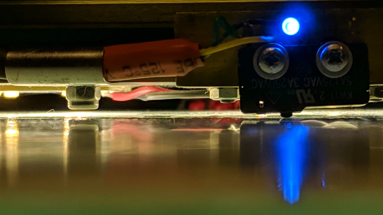
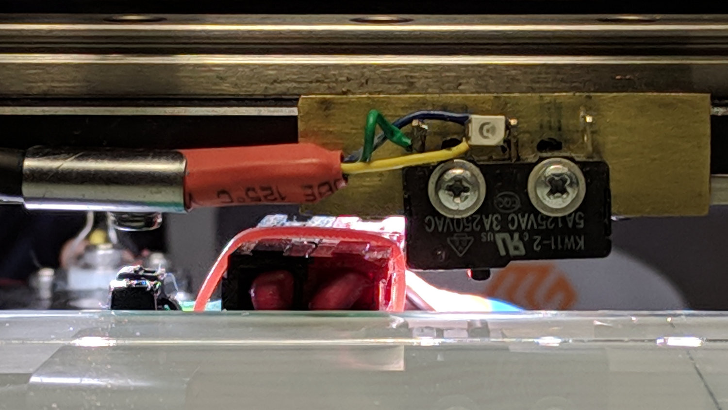
The view from the front shows a slight angle, too:
M2 Z-Axis – activated
There’s a millimeter or so below the nuts holding the X-axis linear slide in place, because the original 18 mm M3 SHCS are now 16 mm long (having shotgunned the metric SHCS and BHCS situation some time ago) and the washers are gone.
They’re all nylon lock nuts except for the one just to the left of the switch, providing barely enough clearance for the Powerpole connectors on the hotrod platform:
M2 Z-Axis – platform connector clearance
With the nozzle off the platform to the far right side, Z-axis homing proceeded normally. Manually jogging to Z=+5.0 mm left 2.6 mm of air under the nozzle, so I reset the offset in EEPROM to -2.4 = (2.6 – 5.0) mm:
M206 Z-2.4
M500
The first calibration square came out at 2.91 mm, so I changed the offset to -2.3 mm, got a 2.80 mm square with a firmly squished first layer, changed it to -2.5 mm, and got a 3.00 mm square for my efforts.
An array of five squares showed the platform remains level to within +0.05 / -0.07 mm:
M2 Platform Alignment Check – 2019-02-06
I defined it to be Good Enough™ and quit while I was ahead.
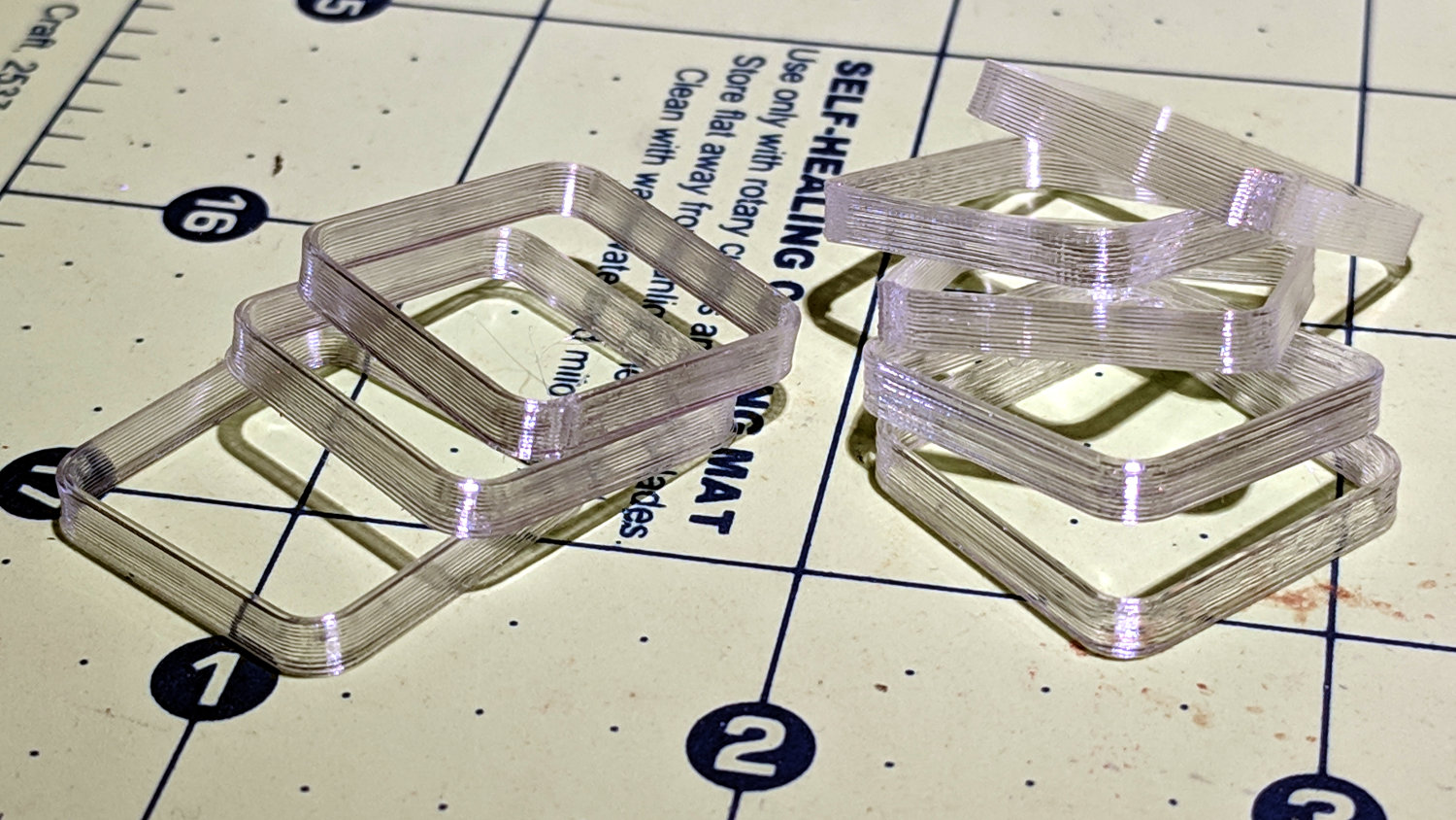
The bottom two squares in the left pile have squished first layers. The rest look just fine:
M2 Z-Axis – switch offset calibration squares
The whole set-and-test process required about 45 minutes, most of which was spent waiting for the platform to reach 90 °C in the 14 °C Basement Laboratory.
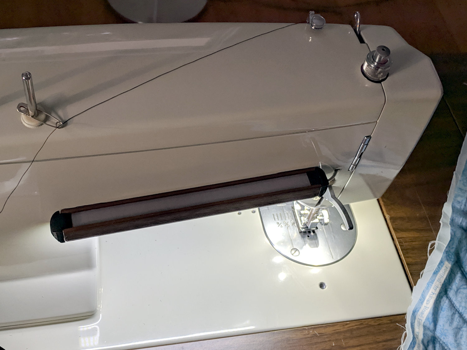
With the Juki TL-2010Q all lit up, it seemed reasonable to apply the same technique to the Kenmore 158 sewing machine a few feet away:
Kenmore 158 COB LED – installed
In an ideal world, I’d match the COB LED module to the opening under the machine’s arm, but module length isn’t a free variable, so it sticks out a bit on both sides.
The 1/4 inch QD connectors on the AC power are marginally OK in this situation, as they’re tucked under the sewing table out of harm’s way. The other end of the AC line cord burrows into the sewing machine’s guts and isn’t easily removed, so this was the least-awful place for a connection.
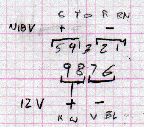
The LED connector pinout:
Kenmore 158 COB LED – Power supply DE-9 pinout
The black cable comes from my lifetime supply of lovely supple flexible 28-ish AWG 9-conductor serial cables with molded-on male connectors.
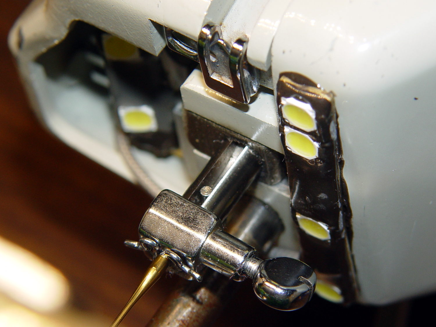
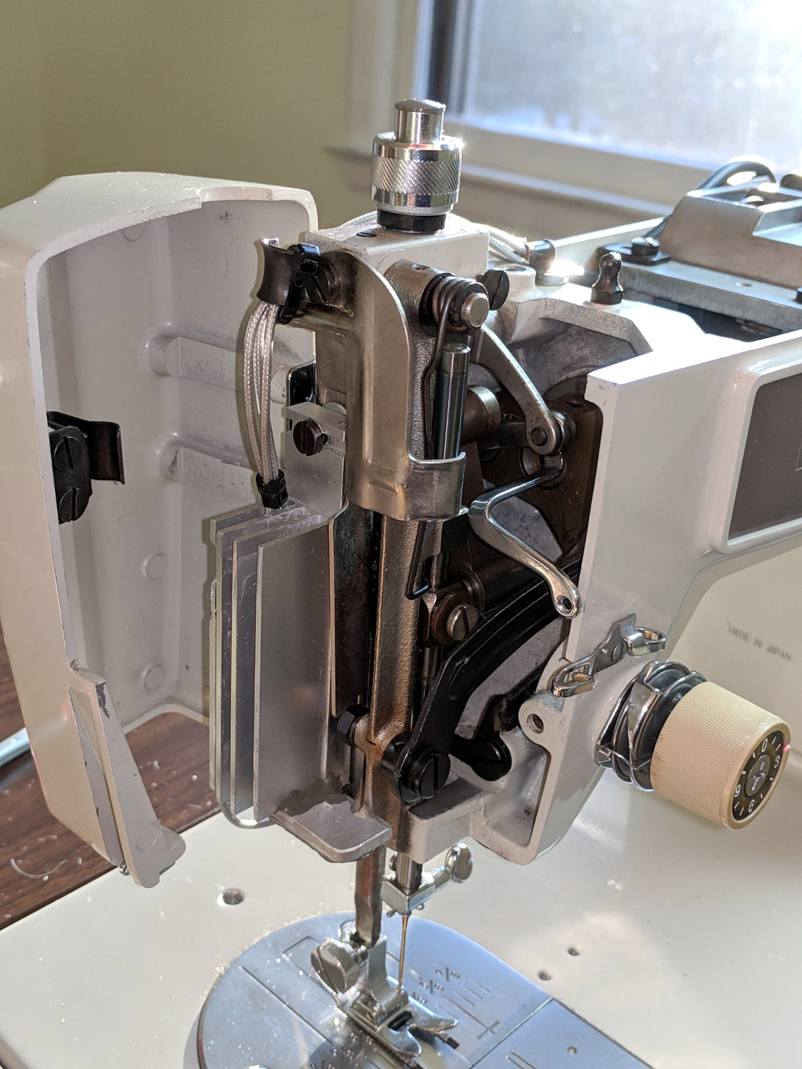
I used some silver-plated / Teflon-insulated coaxial cable for the COB LED wiring. It burrows into the guts of the machine through a gap above the presser foot lift lever, then joins up with similar cables from the other LEDs routed through the (grossly oversized) heatsink fins:
Kenmore 158 COB LED – endcap wire routing
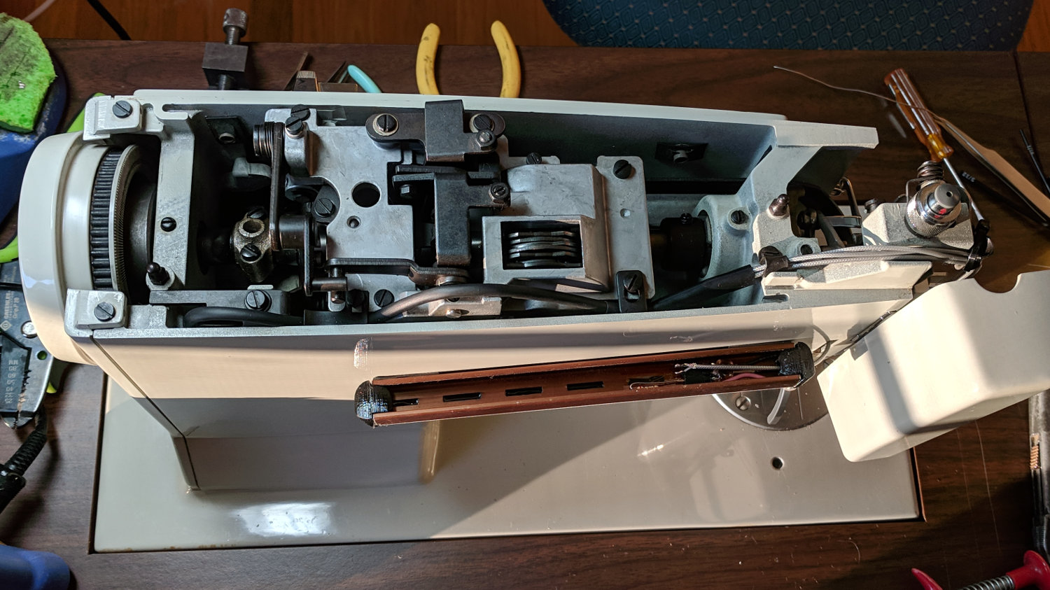
The cables meet the repurposed serial cable inside the arm, following the original route of the 120 VAC wires formerly lighting the glowworm incandescent bulb in the endcap:
Kenmore 158 COB LED – machine assembly
What’s not obvious in that picture: the cables pass under two stamped steel guides and through two stamped steel clamps, each secured to the frame by a cheese head screw in a tapped hole. They definitely don’t make ’em like they used to!
A 2.0 Ω ballast resistor produced the right amount of light, dropping 780 mV to run the LEDs at 390 mA and burning 300 mW. This supply produces 12.0 V at that current, so the COB LEDs run at 11.2 V and dissipate only 4.4 W.
The lower output voltage (compared to the supply on the Juki) is probably the result of the higher load from the SMD LEDs lighting up the area around the needle. We cranked up their voltage to match the COB LEDs, so they’re surely conducting more than the original (guesstimated) 50 mA apiece = 300 mA total. I have no convenient (pronounced “easy”) way to measure either their current or voltage; when the light’s good, it’s all good.
The other Kenmore 158 machines will eventually get the same treatment, but not right now.
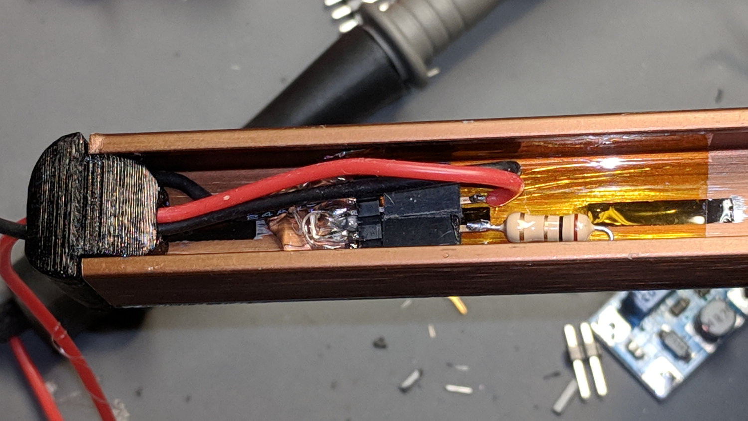
The COB LED module claims to run at 12 V and 6 W, so it expects to draw 500 mA. First pass measurements showed 500 mA happened at 11.6 V:
Juki TL-2010Q COB LED – ballast resistor test
The 12 VDC supply actually produced 12.1 V at 500 mA, so a 1 Ω 1/2 W resistor should produce the right current:
Juki TL-2010Q COB LED – heatsink endcap – internal connections
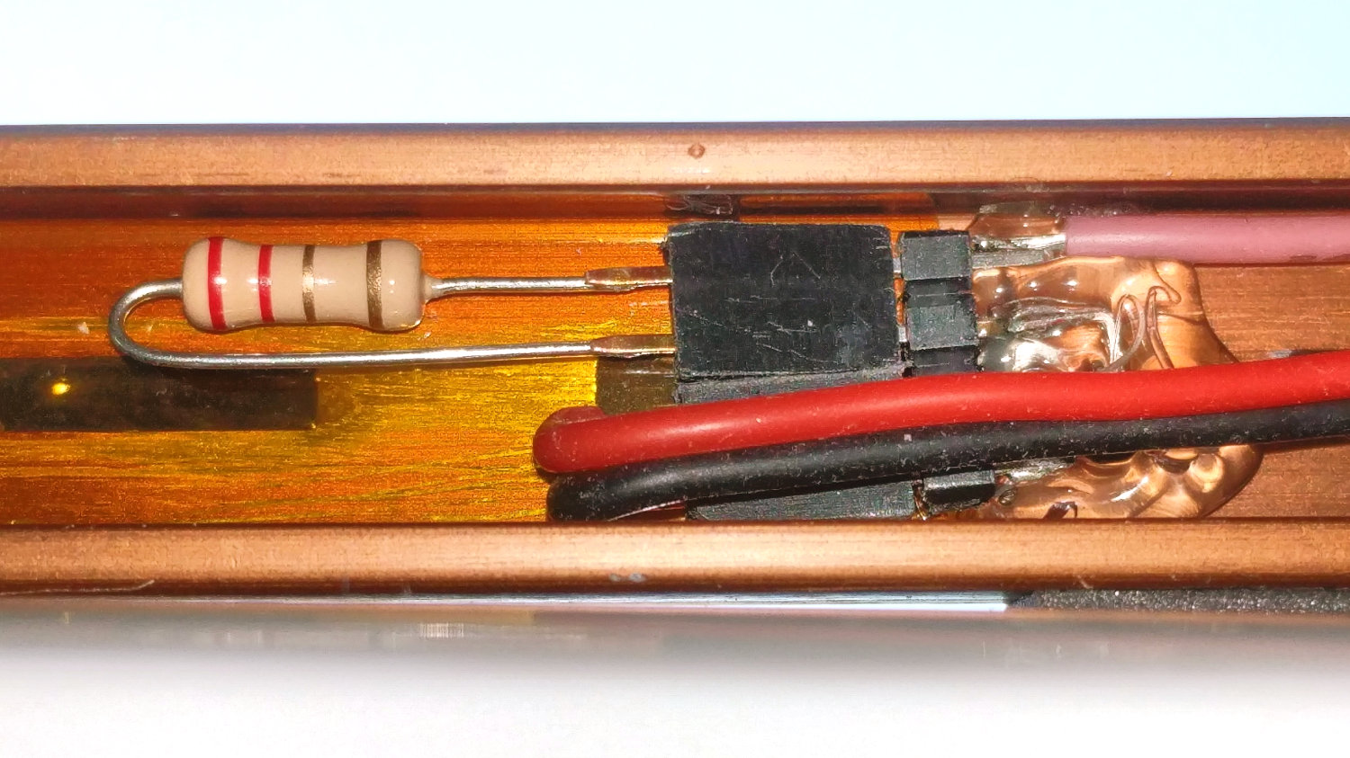
Which it did, but the Customer Base judged 6 W to be far too much light. A 2.7 Ω resistor seemed too dim, so we settled on 2.2 Ω:
Juki TL-2010Q COB LED – 2.2 ohm header
For the record, a 2.2 Ω resistor drops 980 mV and dissipates 440 mW, probably too close to its 500 mW rating. The supply produces 12.2 VDC at 450 mA, so the LEDs run at 11.2 V and dissipate 5 W; the heatsink remains pleasantly warm to the touch.
The hot melt glue anchoring the pin header won’t win any prizes, but it sticks like glue to the Kapton tape and, in any event, there’s not much to go wrong in there.
A cardboard cover hides the ugly details:
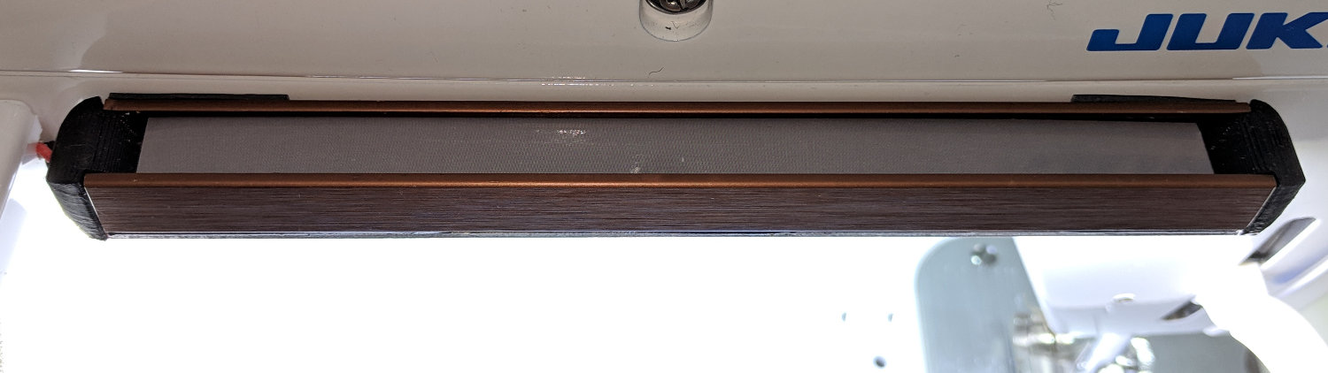
Juki TL-2010Q COB LED – installed
And then It Just Works™:
Juki TL-2010Q COB LED – installed – rear view
As evidenced by the glove fingertips, she does a lot of sewing and I’m glad I can shed some light on the subject …
The wires to my earlier LED lights on Mary’s Kenmore 158 produced one absolute requirement: the Juki TL-2010Q lights must not have any external wiring. Some experimentation showed putting the COB LED module across the rear of the arm, just over the opening, would spill enough light to the front:
Juki TL-2010Q COB LED – installed – rear view
Juki’s teeny OEM SMD LED in the endcap, just above the far side of the needle, casts a dim glow over her left hand. Although they deem it sufficient, I’ll fix that in the near future.
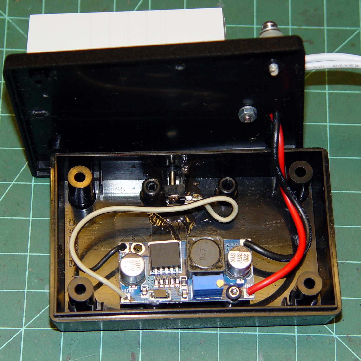
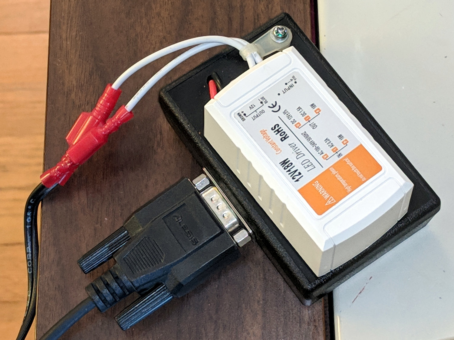
The machine’s power supply and drive motor live inside a plastic cover on the rear of the machine, just to the left of where the LED lights will attach to the arm:
Juki TL-2010Q COB LED – machine power supply
For future reference, a detailed look at the PCB:
Juki TL-2010Q COB LED – machine power supply PCB detail
The yellow-and-blue pair come from the AC power line switch. The brown-and-blue pair carry +120 VDC from the bridge rectifier (left of their connector) to the motor driver. The white-and-blue pair carry filtered 120 VAC from the PCB to the bulky transformer below the motor.
I snipped the white-and-blue pair, added Y connections, and threaded the wires through the vent slots to the 12 VDC power supply:
Juki TL-2010Q COB LED – 12 V supply wiring
If I had to do it again, I’d cut the white-and-blue pair an inch further away from the transformer, so as to move the butt splice connectors around the corner of the frame, rather than across the back of the transformer frame. The flanged screw boss pretty well fills the space left of the transformer and made it difficult to arrange the new connectors.
The 12 VDC 18 W LED supply attaches to the 120 VAC lines with 1/4 inch quick-disconnects, making it possible, if not easy, to completely remove the cover and LED power supply. You’d install dummy plugs in the vacant QD sockets to keep the AC out of harm’s way.
There’s just enough space to the right of the PCB enclosure to route the LED wires around-and-down to meet the wire nuts. They’re not the most elegant connectors you’ve ever seen, but wire nuts are impossible to confuse with the QD connectors on the AC line.
With that in hand, the power supply almost looks like it grew under the spool flange:
Juki TL-2010Q COB LED – 12 V supply installed
In an ideal world, the label would be right-side-up, but ya can’t have everything. The wires had to be where they are, primarily to avoid snagging on fabric passing through the machine.
The green-and-black PET braid covers the AC wires to make them a little less exposed, but it’s surely unnecessary. I gently singed the braid ends to prevent unraveling.
The COB LED supply wires emerge through a slot filed in the cover:
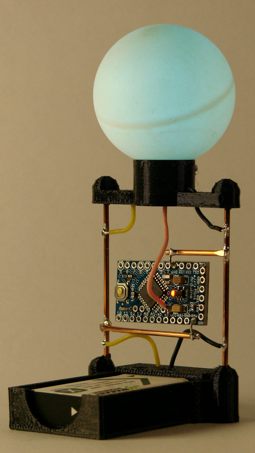
A two-legged spider radome base definitely looks better than the four-legged version:
Arduino Pro Mini – NP-BX1 – radome
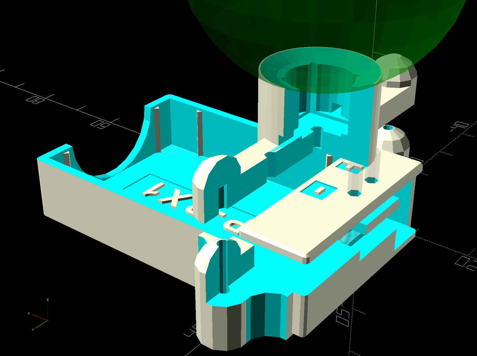
The radome base now has a hole punched in its bottom for the data lead, with the two power wires going out the sides as before:
Arduino Pro Mini Battery Holder – SK6812 radome base
The alert reader will notice the vertical strut on the far side doesn’t go directly into the center of its base fitting. I attempted a bit of cosmetic repair on the horizontal wire below the Pro Mini and discovered, not at all to my surprise, (re)soldering a connection to a 14 AWG copper wire an inch away from a 3D printed base doesn’t work well at all.
Doesn’t affect the function and, as nobody will ever notice, I’ll leave it be.