Homeostasis is a thing:

On the other paw, the eyeballometric trend line since mid-April slopes at -1 lb/month and arrives at just over 150 lb in December, so progress continues apace.
The Smell of Molten Projects in the Morning
Ed Nisley's Blog: Shop notes, electronics, firmware, machinery, 3D printing, laser cuttery, and curiosities. Contents: 100% human thinking, 0% AI slop.
Making the world a better place, one piece at a time
Homeostasis is a thing:
On the other paw, the eyeballometric trend line since mid-April slopes at -1 lb/month and arrives at just over 150 lb in December, so progress continues apace.
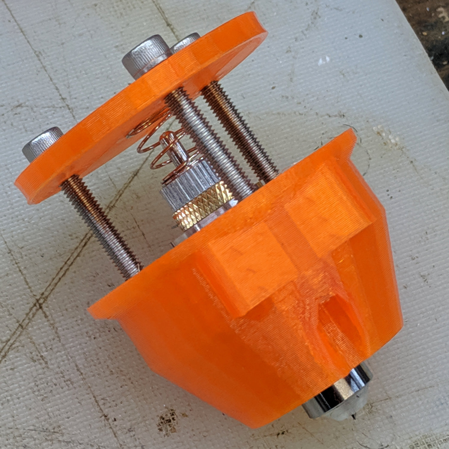
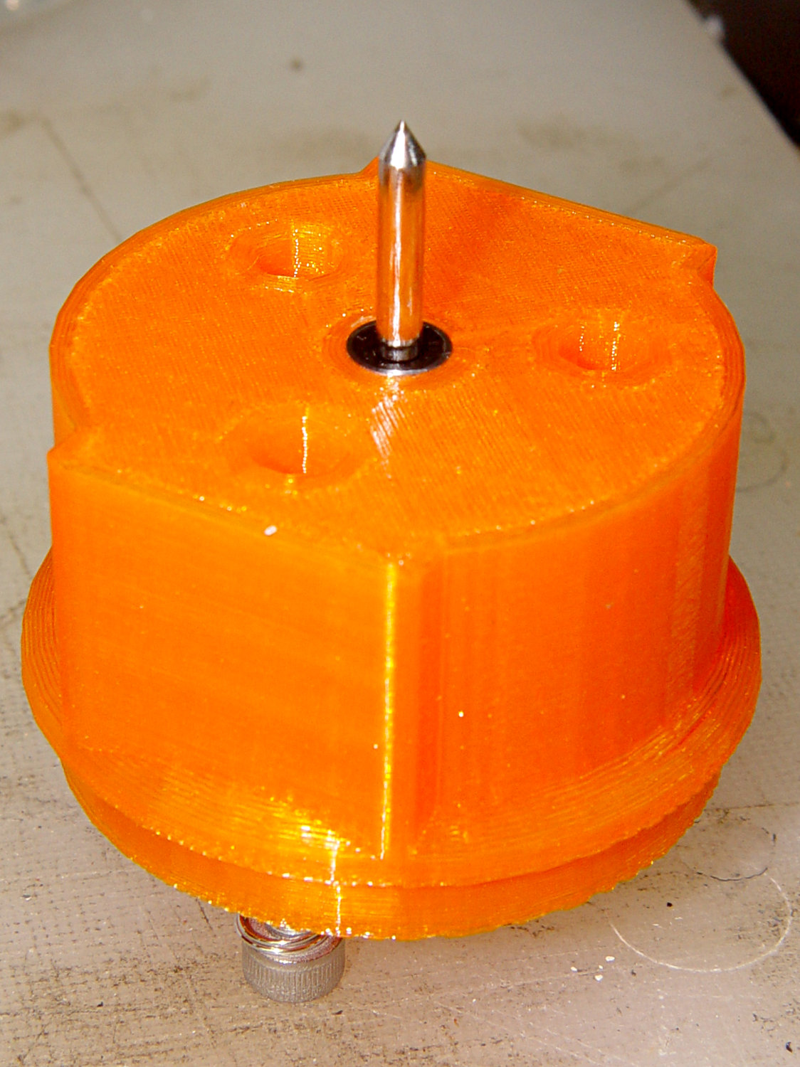
Having a single spring and a fixed upper plate works much better than the first version:

The (lubricated!) nyloc nuts under the plate provide a little friction and stabilize the whole affair.
The solid model has the same stylin’ tapered snout as the LM12UU drag knife mount:
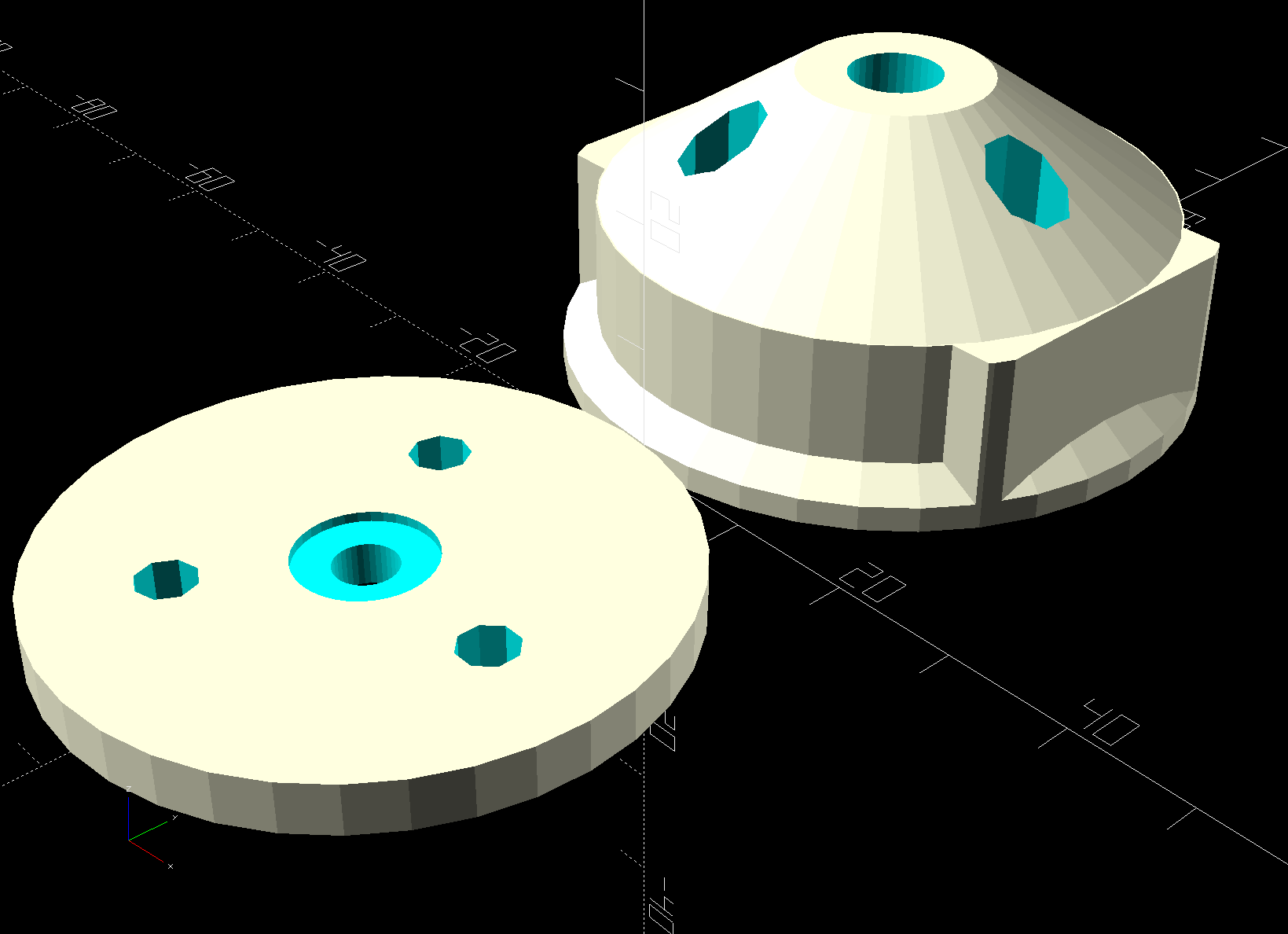
The spring seats in the plate recess, with the 3 mm shank passing through the hole as the tool holder presses the tip against the workpiece.
I diamond-filed a broken carbide end mill to make a slotting tool:
Lacking any better method (“a tiny clip spreader tool”), I rammed the Jesus clip the length of the shank with a (loose-fitting) chuck in the tailstock:

Even without nyloc nuts, the first test worked fine:
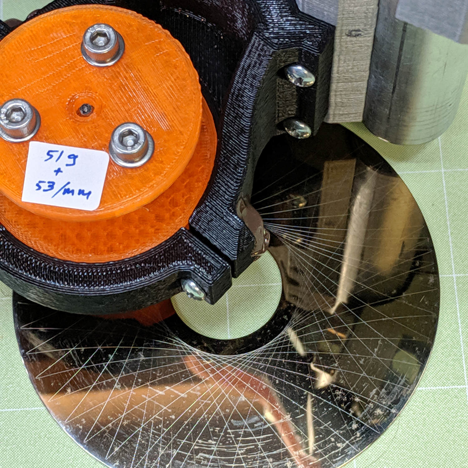
The 53 g/mm spring rate may be too low for serious engraving, but it suffices for subtle Guilloché patterns on scrap platters.
The OpenSCAD source code as a GitHub Gist:
| // Drag Knife Holder using LM12UU linear bearing | |
| // Ed Nisley KE4ZNU – 2019-04-26 | |
| // 2019-05-09 LM3UU for diamond scribe | |
| // 2019-05-28 taper end, single spring around shaft | |
| Layout = "Build"; // [Build, Show, Puck, Mount, Plate] | |
| /* [Extrusion] */ | |
| ThreadThick = 0.25; // [0.20, 0.25] | |
| ThreadWidth = 0.40; // [0.40, 0.40] | |
| /* [Hidden] */ | |
| Protrusion = 0.1; // [0.01, 0.1] | |
| HoleWindage = 0.2; | |
| inch = 25.4; | |
| function IntegerMultiple(Size,Unit) = Unit * ceil(Size / Unit); | |
| ID = 0; | |
| OD = 1; | |
| LENGTH = 2; | |
| //- Adjust hole diameter to make the size come out right | |
| module PolyCyl(Dia,Height,ForceSides=0) { // based on nophead's polyholes | |
| Sides = (ForceSides != 0) ? ForceSides : (ceil(Dia) + 2); | |
| FixDia = Dia / cos(180/Sides); | |
| cylinder(r=(FixDia + HoleWindage)/2,h=Height,$fn=Sides); | |
| } | |
| //- Dimensions | |
| // Knife holder & suchlike | |
| KnifeBody = [3.0,9.0,2.0]; // washer epoxied to diamond shaft, with epoxy fillet | |
| Spring = [9.5,10.0,3*ThreadThick]; // compression spring around shaft, LENGTH = socket depth | |
| WallThick = 4.0; // minimum thickness / width | |
| Screw = [4.0,8.5,8.0]; // holding it all together, OD = washer | |
| Insert = [4.0,6.0,10.0]; // brass insert | |
| Bearing = [3.0,7.0,2*10.0 + WallThick]; // linear bearing body (pair + small gap) | |
| // Basic shape of DW660 snout fitting into the holder | |
| // Lip goes upward to lock into MPCNC mount | |
| Snout = [44.6,50.0,9.6]; // LENGTH = ID height | |
| Lip = 4.0; // height of lip at end of snout | |
| Plate = [KnifeBody[ID],Snout[OD] – WallThick,WallThick]; // spring reaction plate | |
| PuckOAL = max(Bearing[LENGTH],(Snout[LENGTH] + Lip)); // total height of DW660 fitting | |
| echo(str("PuckOAL: ",PuckOAL)); | |
| Key = [Snout[ID],25.7,(Snout[LENGTH] + Lip)]; // rectangular key | |
| NumScrews = 3; | |
| ScrewBCD = 2.5*(Bearing[OD]/2 + Insert[OD]/2 + WallThick); | |
| NumSides = 9*4; // cylinder facets (multiple of 3 for lathe trimming) | |
| module DW660Puck() { | |
| translate([0,0,PuckOAL]) | |
| rotate([180,0,0]) { | |
| cylinder(d=Snout[OD],h=Lip/2,$fn=NumSides); | |
| translate([0,0,Lip/2]) | |
| cylinder(d1=Snout[OD],d2=Snout[ID],h=Lip/2,$fn=NumSides); | |
| cylinder(d=Snout[ID],h=(Snout[LENGTH] + Lip),$fn=NumSides); | |
| translate([0,0,(Snout[LENGTH] + Lip) – Protrusion]) | |
| cylinder(d1=Snout[ID],d2=2*WallThick + Bearing[OD],h=PuckOAL – (Snout[LENGTH] + Lip),$fn=NumSides); | |
| intersection() { | |
| translate([0,0,0*Lip + Key.z/2]) | |
| cube(Key,center=true); | |
| cylinder(d=Snout[OD],h=Lip + Key.z,$fn=NumSides); | |
| } | |
| } | |
| } | |
| module MountBase() { | |
| difference() { | |
| DW660Puck(); | |
| translate([0,0,-Protrusion]) // bearing | |
| PolyCyl(Bearing[OD],2*PuckOAL,NumSides); | |
| for (i=[0:NumScrews – 1]) // clamp screws | |
| rotate(i*360/NumScrews) | |
| translate([ScrewBCD/2,0,-Protrusion]) | |
| rotate(180/8) | |
| PolyCyl(Insert[OD],2*PuckOAL,8); | |
| } | |
| } | |
| module SpringPlate() { | |
| difference() { | |
| cylinder(d=Plate[OD],h=Plate[LENGTH],$fn=NumSides); | |
| translate([0,0,-Protrusion]) // ample shaft clearance | |
| PolyCyl(1.5*KnifeBody[ID],2*PuckOAL,NumSides); | |
| // translate([0,0,Plate[LENGTH] – KnifeBody[LENGTH]]) // flange, snug fit | |
| // PolyCyl(KnifeBody[OD],KnifeBody[LENGTH] + Protrusion,NumSides); | |
| translate([0,0,Plate[LENGTH] – Spring[LENGTH]]) // spring retainer | |
| PolyCyl(Spring[OD],Spring[LENGTH] + Protrusion,NumSides); | |
| for (i=[0:NumScrews – 1]) // clamp screws | |
| rotate(i*360/NumScrews) | |
| translate([ScrewBCD/2,0,-Protrusion]) | |
| rotate(180/8) | |
| PolyCyl(Screw[ID],2*PuckOAL,8); | |
| } | |
| } | |
| //—– | |
| // Build it | |
| if (Layout == "Puck") | |
| DW660Puck(); | |
| if (Layout == "Plate") | |
| SpringPlate(); | |
| if (Layout == "Mount") | |
| MountBase(); | |
| if (Layout == "Show") { | |
| MountBase(); | |
| translate([0,0,1.5*PuckOAL]) | |
| rotate([180,0,0]) | |
| SpringPlate(); | |
| } | |
| if (Layout == "Build") { | |
| translate([0,Snout[OD]/2,PuckOAL]) | |
| rotate([180,0,0]) | |
| MountBase(); | |
| translate([0,-Snout[OD]/2,0]) | |
| SpringPlate(); | |
| } |
The tiny voice inside our Ooma Telo 2 box died, although the VOIP phone service continued to work fine. A bit of searching showed the speaker seems to be the weak link.
Well, I can fix that.
Start by prying the recessed top panel off the case:
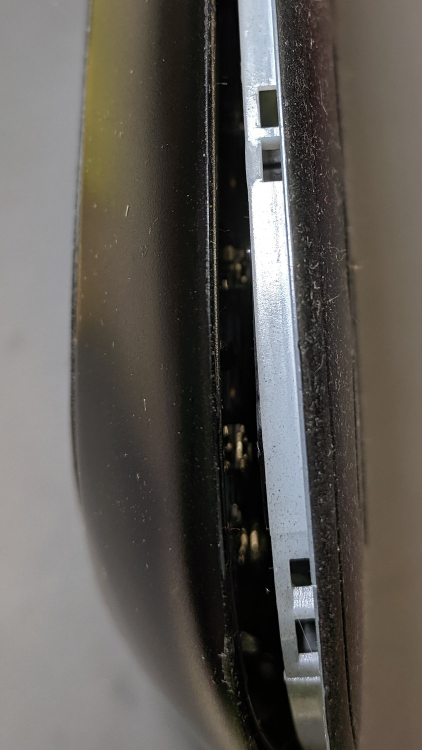
Remove the circuit board to expose the tiny speaker, taking care not to rip the tiny wires out of the tiny connector:

You can’t measure a dead speaker, but it seems to be an 8 Ω unit.
The speaker sits in a rubber surround, with a foam rubber cushion against the PCB, tucked into a walled garden stiffening the case:

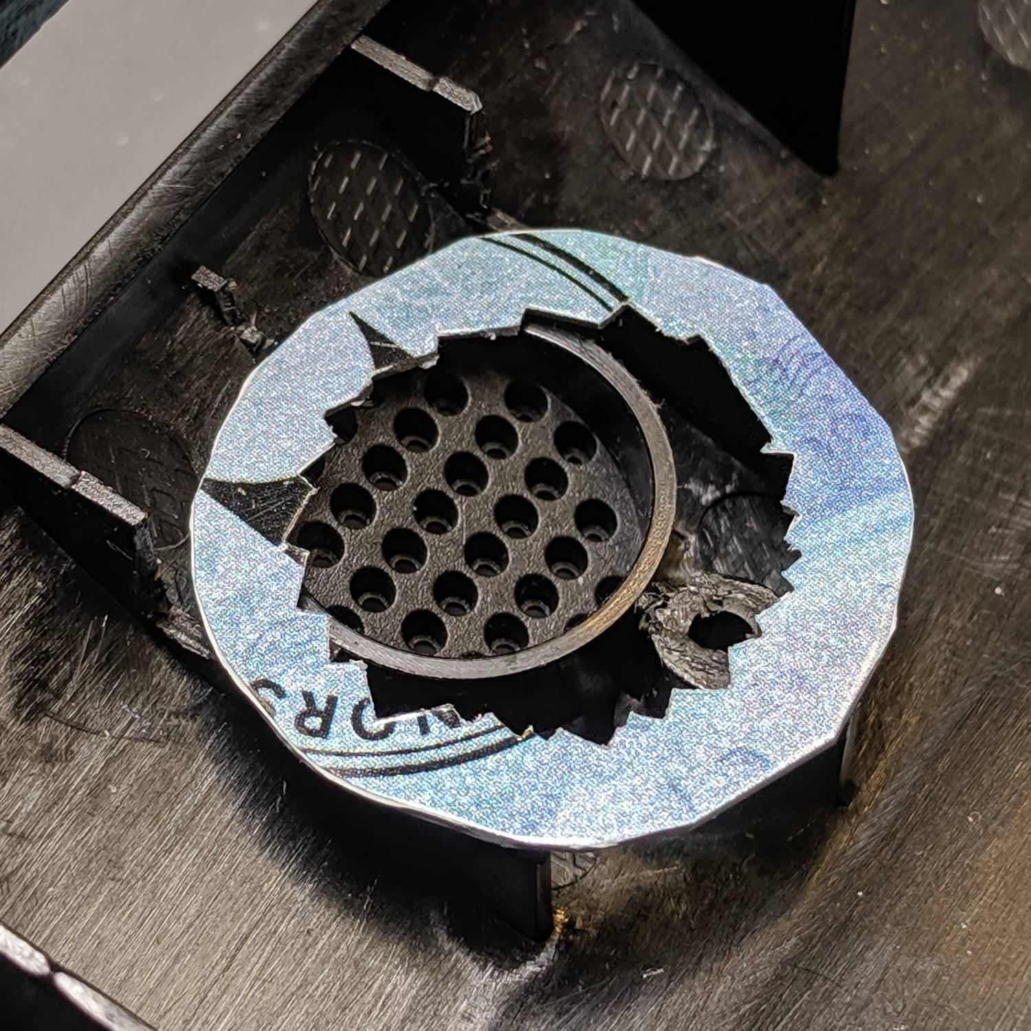
I don’t happen to have a tiny 8 Ω speaker, but I do have a bunch of small speakers (Update: 28 mm OD), so I bulldozed those walls with a flush cutting pliers and a bit of cussing to make room:
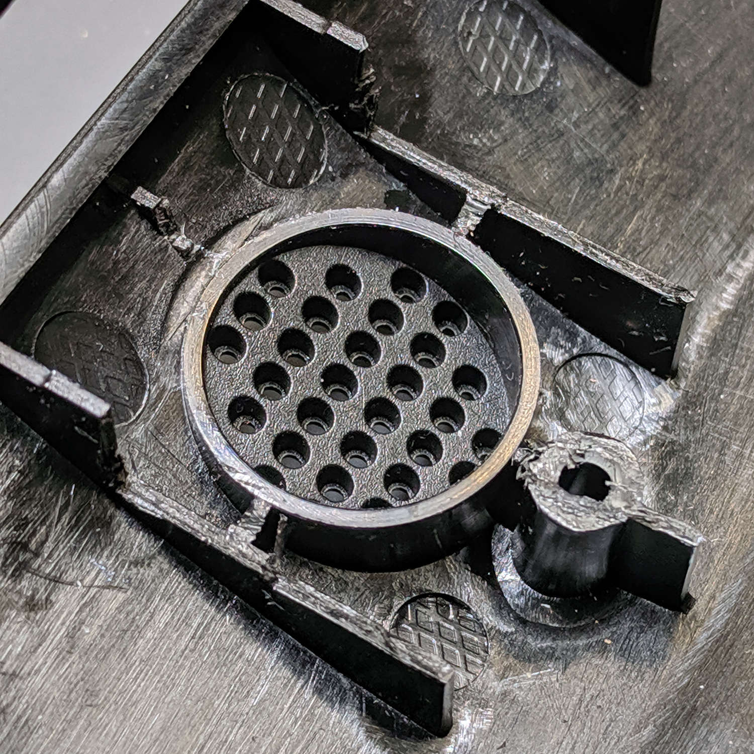
Nibble an adapter ring to match the rim of the new speaker, thereby routing the sound out those little holes, and hot-melt glue it in place:
Hot-melt glue the new speaker in place atop the adapter, taking care to fill all the edges / cracks / crevices below it with an impenetrable wall of glop:
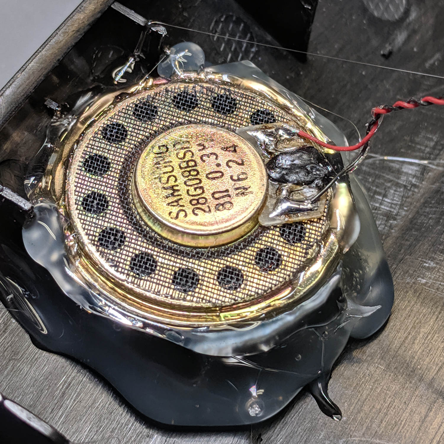
The sealing part turns out to be critical with these little speakers, because a leak from front to back will pretty much cancel all the sound from the cone.
Cut the wires off the old speaker, affix to the new one, replace the PCB, snap the case lid in place, and it sounds better than new.
Millions of transistors in those ICs, but Ooma can’t spec a good speaker? Maybe they should have used a bigger speaker to begin with; ya never know.
Mostly, the Tiny Bandsaw™ cuts thin sheets, where having the blade at a slight angle off perpendicular doesn’t make much difference. I recently started to cut a thicker block and thought the blade looked a bit slanted, so I deployed the Tiny Square™ to set it properly:
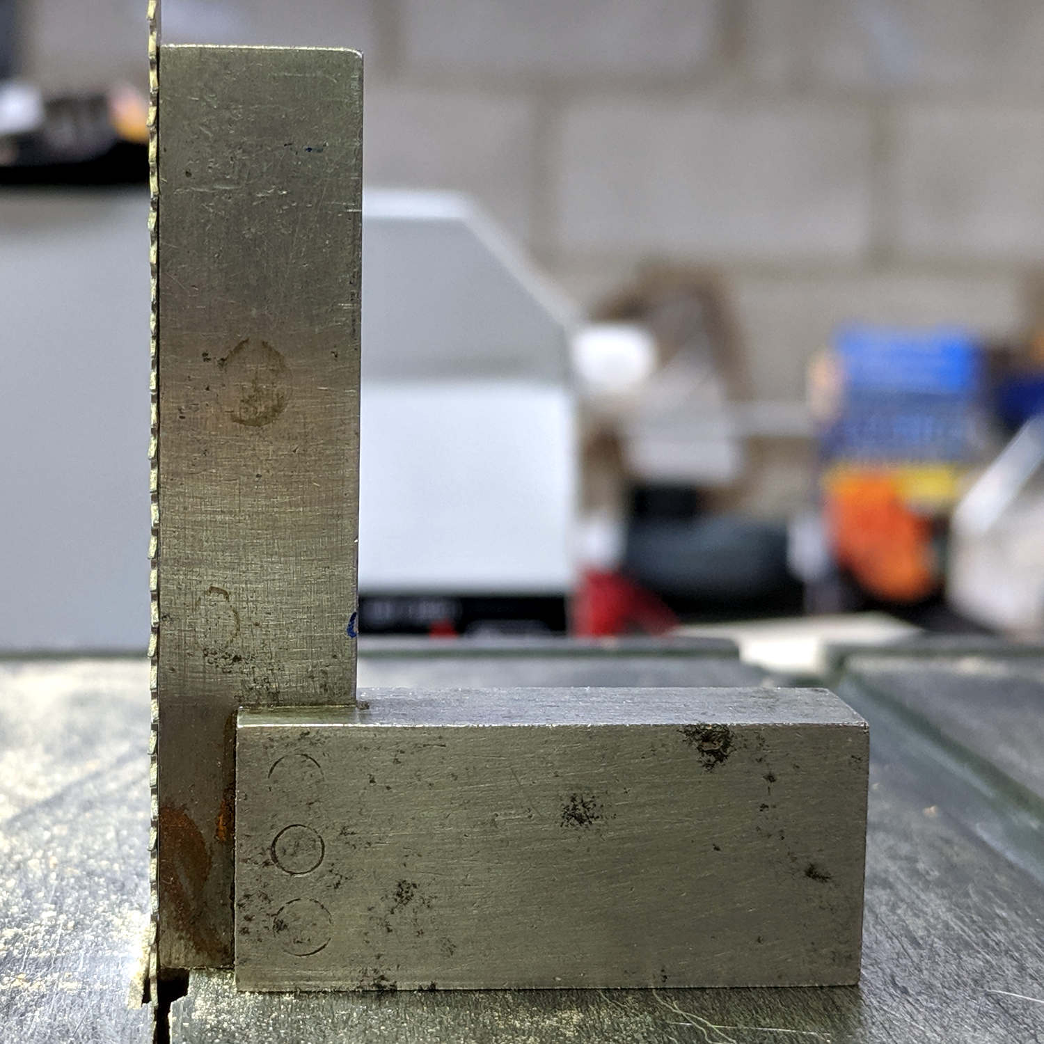
Which produced this result on the blade angle gauge under the table:
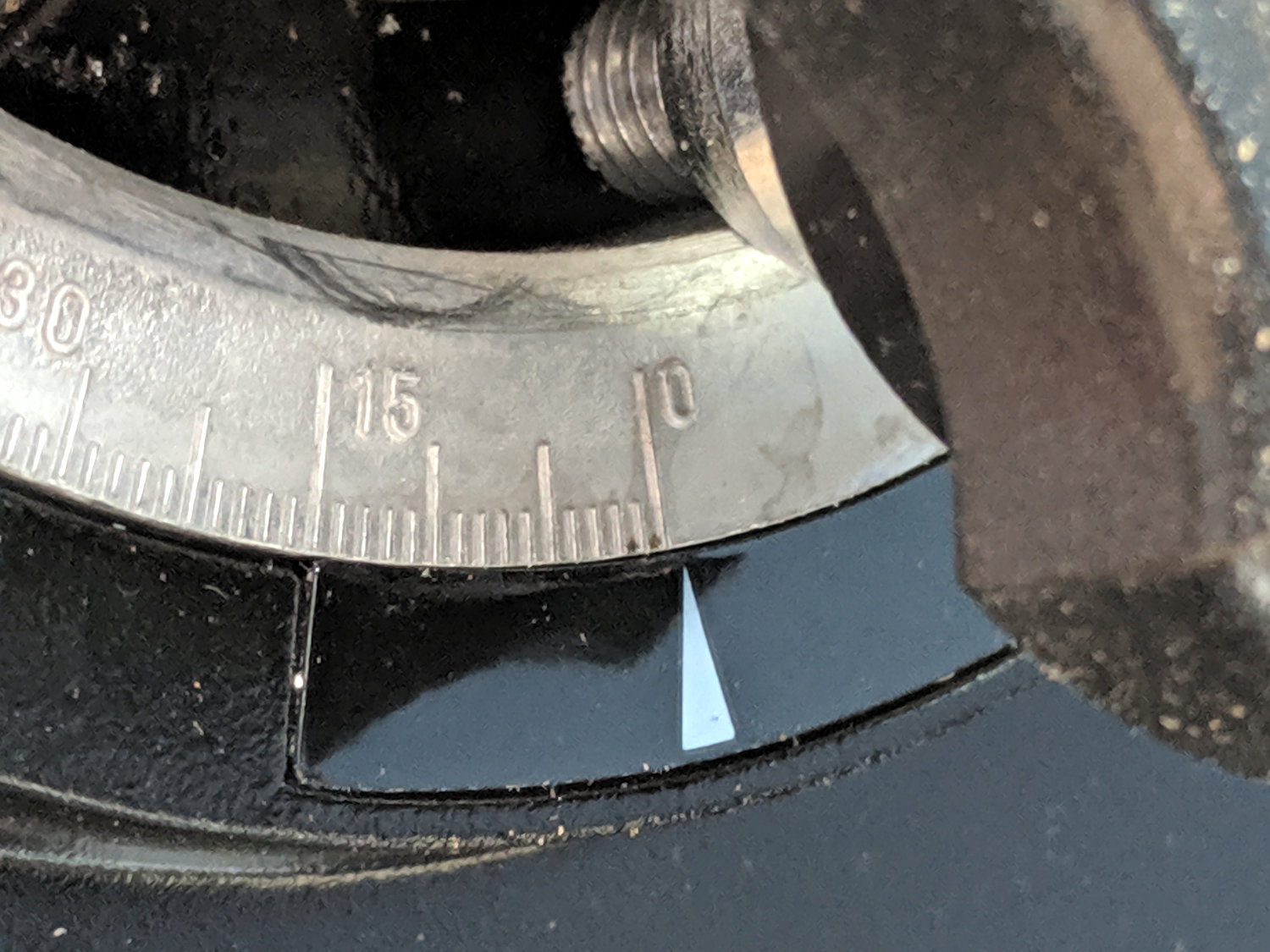
Huh.
The scale pointer is printed on what’s basically a sticker. The QC regime for the bandsaw apparently doesn’t ensure the pointer appears at the proper place on the sticker, nor does it verify the overall alignment.
I peeled the sticker off off, trimmed the near edge, and re-stuck it with the pointer aimed properly:

It makes me feel better, anyway …
Now, as why they put the scale pointer behind the table clamp knob, where it can’t be seen directly, that remains a mystery.
When we bought this house, it had its original clothes dryer, which was vented directly through the wall with a few inches of 3×10 inch square duct. Alas, contemporary dryers use 4 inch round hoses, so I conjured a round-to-square adapter from a length of air handler duct:

I’d used … wait for it … duct tape to hold the end caps on, because I knew I’d be taking it apart to clean out the fuzz every now & again. The most recent cleanout occurred when I noticed the end cap had eased its way out of the adapter, releasing warm fuzzy air behind the dryer.
The solution, which I should have done decades ago, holds the end caps in place with sheet metal screws:

A pair of small clamps held everything in the proper location while I applied a suitable step drill and installed the screw:

Now the duct tape just seals the gaps, rather than holding against the minimal pressure in the box, and it should be all good until the next cleanout.
So simple I should’a done it decades ago. Right?
The 12 mm drag knife holder on the left slides nicely in an LM12UU bearing:
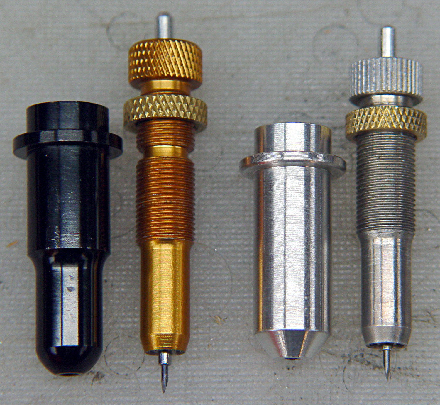
However, its aluminum body isn’t really intended as a bearing surface and it extends only halfway through the LM12UU, so I finally got around to modifying the 11.5 mm body on the right to fit into a section of 12 mm ground shaft:

The general idea is to turn the body down to 10 mm OD; the picture shows the first pass over the nose after turning the far end down and removing the flange in the process. Exact concentricity of both ends isn’t important (it gets epoxied into a 10 mm hole through the 12 mm ground shaft), but it came out rather pretty:

The ground shaft started as a pen holder:
I knocked off the ring and bored the interior to fit the 10 mm knife body. The large end of the existing bore came from a 25/64 inch = 9.92 mm drill, so it was just shy of 10.0 mm, and I drilled the small end upward from 0.33 inch = 8.4 mm.
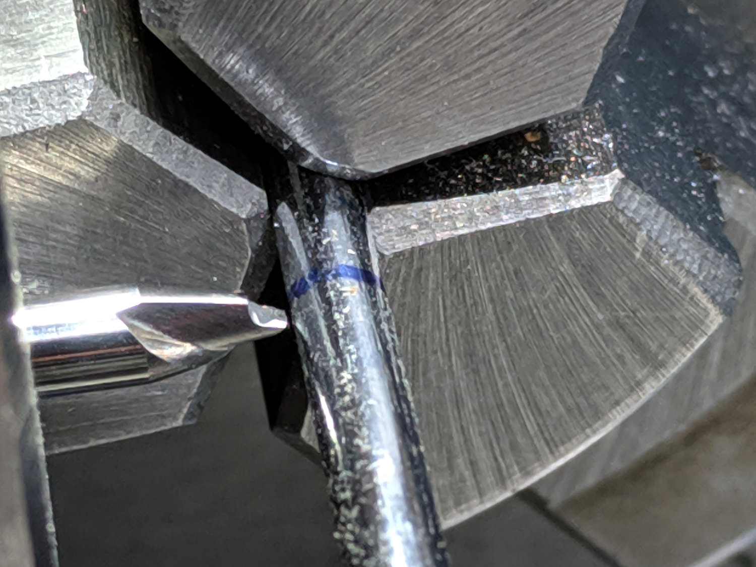
The smallest trio of a new set of cheap carbide boring bars allegedly went into a 5/16 inch = 7.9 mm bore, but I had to file the bar body down and diamond-file more end relief into the carbide for clearance inside the drilled hole:

I blued the bit, kissed it against the drilled bore, filed off whatever wasn’t blued, and iterated until the carbide edge started cutting. Sissy cuts all the way, with no pix to show for all the flailing around.
Epoxying the turned-down drag knife body into the shaft: anticlimactic.
The solid model features a stylin’ tapered snout:

Which gets an LM12UU bearing rammed into place:

The steel block leaves the bearing flush with the plastic surface, rather than having it continue onward and indent itself into the wood; I can learn from my mistakes.
The new idea: a single spring pressing the knife holder downward, reacting against a fixed plastic plate:
Unlike the previous design, the upper plate doesn’t move, so there’s no problem caused by sliding along the screw threads. I should run nylock nuts up against the plate to keep it in place, stiffen the structure, and provide some friction to keep the screws from loosening.
The top of the knife holder now has a boss anchoring the spring:

As you’d expect, the ground shaft slides wonderfully in the bearing, because that’s what it’s designed to do, and the knife has essentially zero stiction and friction at any point along the bearing, which is exactly what I wanted.
The spring, from the same assortment as all the others, has a 48 g/mm rate.
The OpenSCAD source code as a GitHub Gist:
| // Drag Knife Holder using LM12UU linear bearing | |
| // Ed Nisley KE4ZNU – 2019-04-26 | |
| // 2019-06-01 Taper the nose | |
| Layout = "Build"; // [Build, Show, Puck, Mount, Plate] | |
| /* [Extrusion] */ | |
| ThreadThick = 0.25; // [0.20, 0.25] | |
| ThreadWidth = 0.40; // [0.40] | |
| /* [Hidden] */ | |
| Protrusion = 0.1; // [0.01, 0.1] | |
| HoleWindage = 0.2; | |
| inch = 25.4; | |
| function IntegerMultiple(Size,Unit) = Unit * ceil(Size / Unit); | |
| ID = 0; | |
| OD = 1; | |
| LENGTH = 2; | |
| //- Adjust hole diameter to make the size come out right | |
| module PolyCyl(Dia,Height,ForceSides=0) { // based on nophead's polyholes | |
| Sides = (ForceSides != 0) ? ForceSides : (ceil(Dia) + 2); | |
| FixDia = Dia / cos(180/Sides); | |
| cylinder(r=(FixDia + HoleWindage)/2,h=Height,$fn=Sides); | |
| } | |
| //- Dimensions | |
| // Basic shape of DW660 snout fitting into the holder | |
| // Lip goes upward to lock into MPCNC mount | |
| Snout = [44.6,50.0,9.6]; // LENGTH = ID height | |
| Lip = 4.0; // height of lip at end of snout | |
| // Knife holder & suchlike | |
| KnifeBody = [12.0,18.0,2.0]; // body OD, flange OD, flange thickness | |
| Spring = [9.5,10.0,3*ThreadThick]; // compression spring loading knife blade | |
| PinAccess = 4.0; // hole to reach knife ejection pin | |
| WallThick = 4.0; // minimum thickness / width | |
| Screw = [4.0,8.5,25.0]; // thread ID, washer OD, length | |
| Insert = [4.0,6.0,10.0]; // brass insert | |
| Bearing = [12.0,21.0,30.0]; // linear bearing body | |
| Plate = [PinAccess,Snout[OD] – WallThick,WallThick]; // spring reaction plate | |
| echo(str("Plate: ",Plate)); | |
| SpringSeat = [0.56,7.2,2*ThreadThick]; // wire = ID, coil = OD, seat depth = length | |
| PuckOAL = max(Bearing[LENGTH],(Snout[LENGTH] + Lip)); // total height of DW660 fitting | |
| echo(str("PuckOAL: ",PuckOAL)); | |
| Key = [Snout[ID],25.7,(Snout[LENGTH] + Lip)]; // rectangular key | |
| NumScrews = 3; | |
| //ScrewBCD = 2.0*(Bearing[OD]/2 + Insert[OD]/2 + WallThick); | |
| ScrewBCD = (Snout[ID] + Bearing[OD])/2; | |
| NumSides = 9*4; // cylinder facets (multiple of 3 for lathe trimming) | |
| module DW660Puck() { | |
| translate([0,0,PuckOAL]) | |
| rotate([180,0,0]) { | |
| cylinder(d=Snout[OD],h=Lip/2,$fn=NumSides); | |
| translate([0,0,Lip/2]) | |
| cylinder(d1=Snout[OD],d2=Snout[ID],h=Lip/2,$fn=NumSides); | |
| cylinder(d=Snout[ID],h=(Snout[LENGTH] + Lip),$fn=NumSides); | |
| translate([0,0,(Snout[LENGTH] + Lip) – Protrusion]) | |
| cylinder(d1=Snout[ID],d2=2*WallThick + Bearing[OD],h=PuckOAL – (Snout[LENGTH] + Lip),$fn=NumSides); | |
| intersection() { | |
| translate([0,0,0*Lip + Key.z/2]) | |
| cube(Key,center=true); | |
| cylinder(d=Snout[OD],h=Lip + Key.z,$fn=NumSides); | |
| } | |
| } | |
| } | |
| module MountBase() { | |
| difference() { | |
| DW660Puck(); | |
| translate([0,0,-Protrusion]) // bearing | |
| PolyCyl(Bearing[OD],2*PuckOAL,NumSides); | |
| for (i=[0:NumScrews – 1]) // clamp screws | |
| rotate(i*360/NumScrews) | |
| translate([ScrewBCD/2,0,-Protrusion]) | |
| rotate(180/8) | |
| PolyCyl(Insert[OD],2*PuckOAL,8); | |
| } | |
| } | |
| module SpringPlate() { | |
| difference() { | |
| cylinder(d=Plate[OD],h=Plate[LENGTH],$fn=NumSides); | |
| translate([0,0,-Protrusion]) // ejection pin hole | |
| PolyCyl(PinAccess,2*Plate[LENGTH],NumSides); | |
| translate([0,0,Plate[LENGTH] – Spring[LENGTH]]) // spring retaining recess | |
| PolyCyl(Spring[OD],Spring[LENGTH] + Protrusion,NumSides); | |
| for (i=[0:NumScrews – 1]) // clamp screws | |
| rotate(i*360/NumScrews) | |
| translate([ScrewBCD/2,0,-Protrusion]) | |
| rotate(180/8) | |
| PolyCyl(Screw[ID],2*PuckOAL,8); | |
| if (false) | |
| for (i=[0:NumScrews – 1]) // coil positioning recess | |
| rotate(i*360/NumScrews) | |
| translate([ScrewBCD/2,0,-Protrusion]) | |
| rotate(180/8) | |
| PolyCyl(SpringSeat[OD],SpringSeat[LENGTH] + Protrusion,8); | |
| } | |
| } | |
| //—– | |
| // Build it | |
| if (Layout == "Puck") | |
| DW660Puck(); | |
| if (Layout == "Plate") | |
| SpringPlate(); | |
| if (Layout == "Mount") | |
| MountBase(); | |
| if (Layout == "Show") { | |
| MountBase(); | |
| translate([0,0,1.6*PuckOAL]) | |
| rotate([180,0,0]) | |
| SpringPlate(); | |
| } | |
| if (Layout == "Build") { | |
| translate([0,Snout[OD]/2,PuckOAL]) | |
| rotate([180,0,0]) | |
| MountBase(); | |
| translate([0,-Snout[OD]/2,0]) | |
| SpringPlate(); | |
| } |
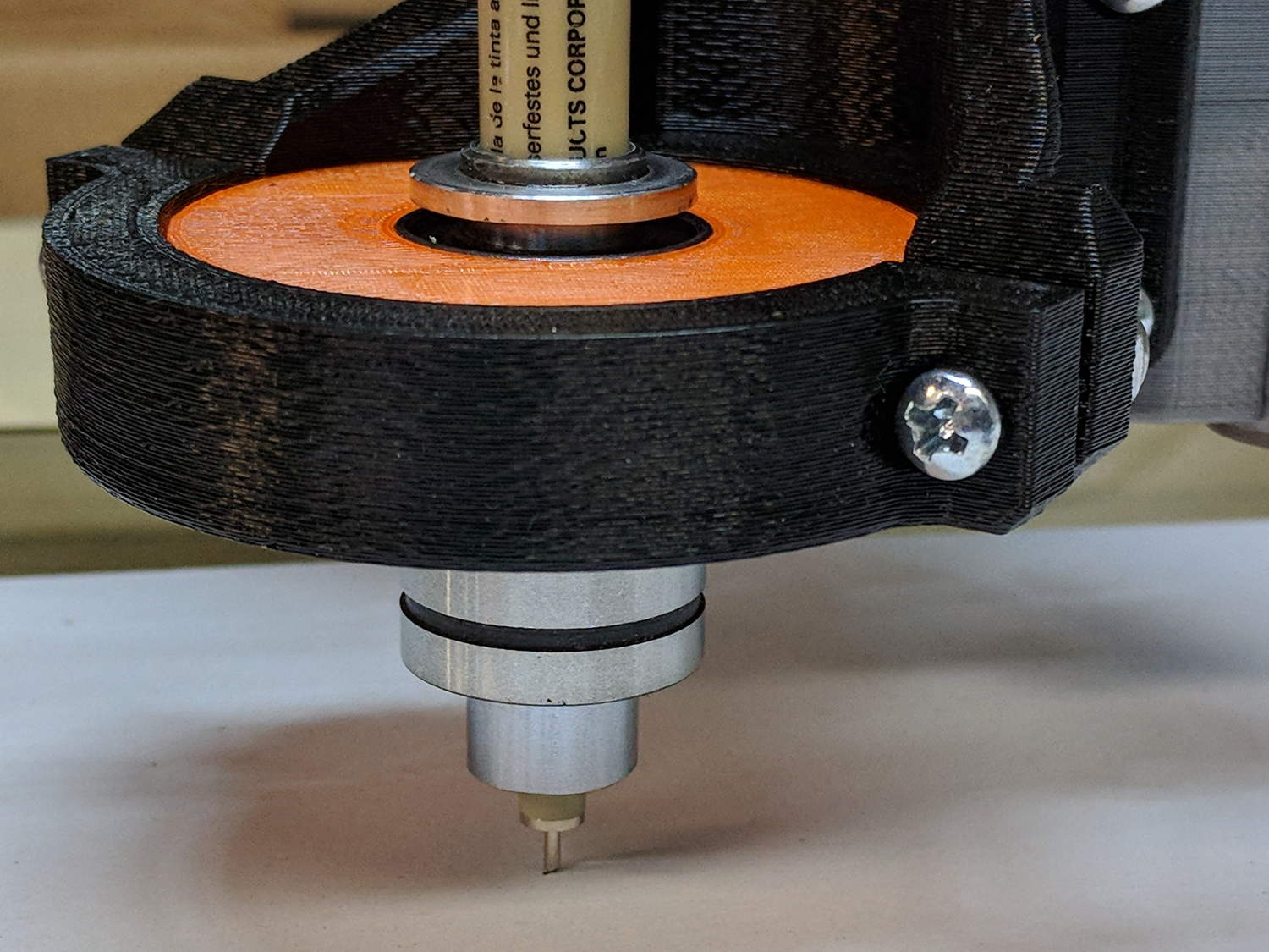
Gripping a diamond engraver in a collet chuck worked well enough, but the MPCNC’s pen holder lacks sufficient downforce and lateral stiffness. The bit has a chrome-ish plated 3 mm shank, so I tinkered up a mount for a pair of LM3UU linear bearings from the LM12UU drag knife holder:
The shank isn’t exactly a precision part, but a few licks with a diamond file knocked off enough of the high spots so it slides reasonably well through the bearings. The bearing alignment is more critical than a simple 3D printed plastic part can provide, so a real version may need bearings in a metal shaft press-fit into the plastic; brute-forcing the bearings into alignment sufficed for now.
The butt end of the shank press-fits into a disk held down with three springs, similar to the LM12UU mount:

It draws Guilloché patterns just fine:

I don’t like how the spring-around-screw motion works, even if it’s OK for small excursions.
