For reasons not relevant here, I recently conjured a pair of tables to support an injured arm (ours are OK!) in the bathroom: one table fitting in the narrow space adjacent to a toilet and the other across the threshold of a walk-in / sit-down shower.
The raw material came from a plastic side table intended for outdoor use:

That’s the Patriotic Blue version, which seemed the least offensive of the colors on offer at the local store.
The plastic pieces unsnap easily enough:
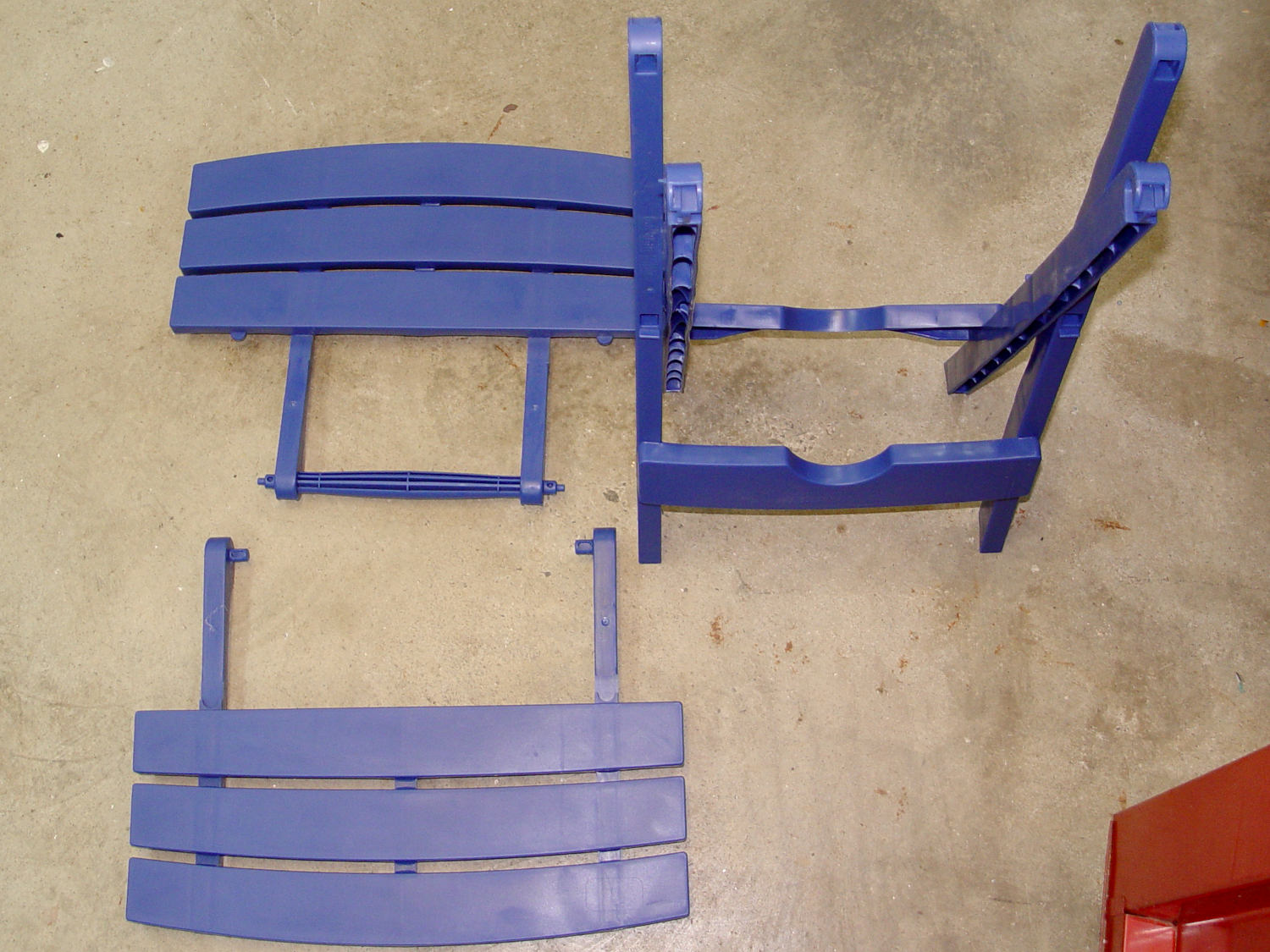
The legs also come apart by pulling outward at the crossover points. You may need to clean the flashing from all the joints, as they’re only as finished as absolutely necessary.
A table about half the width seemed about right, so I sawed the two top plates off their struts, then angled the strut ends to match the new leg angle:
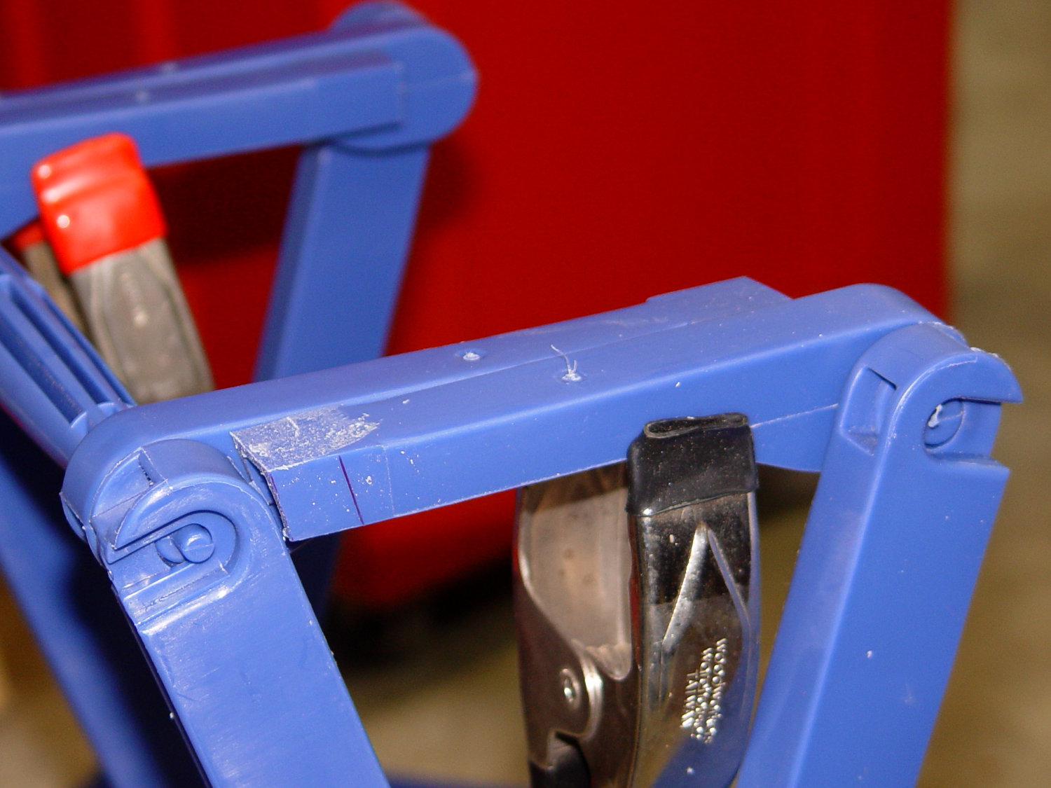
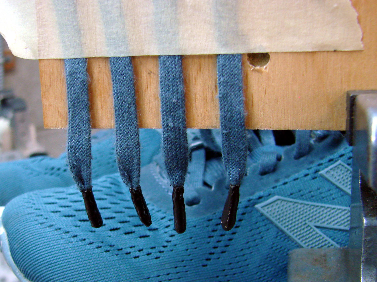
Because it’s now completely floppy, I drilled holes for 5 mm screws through the struts:

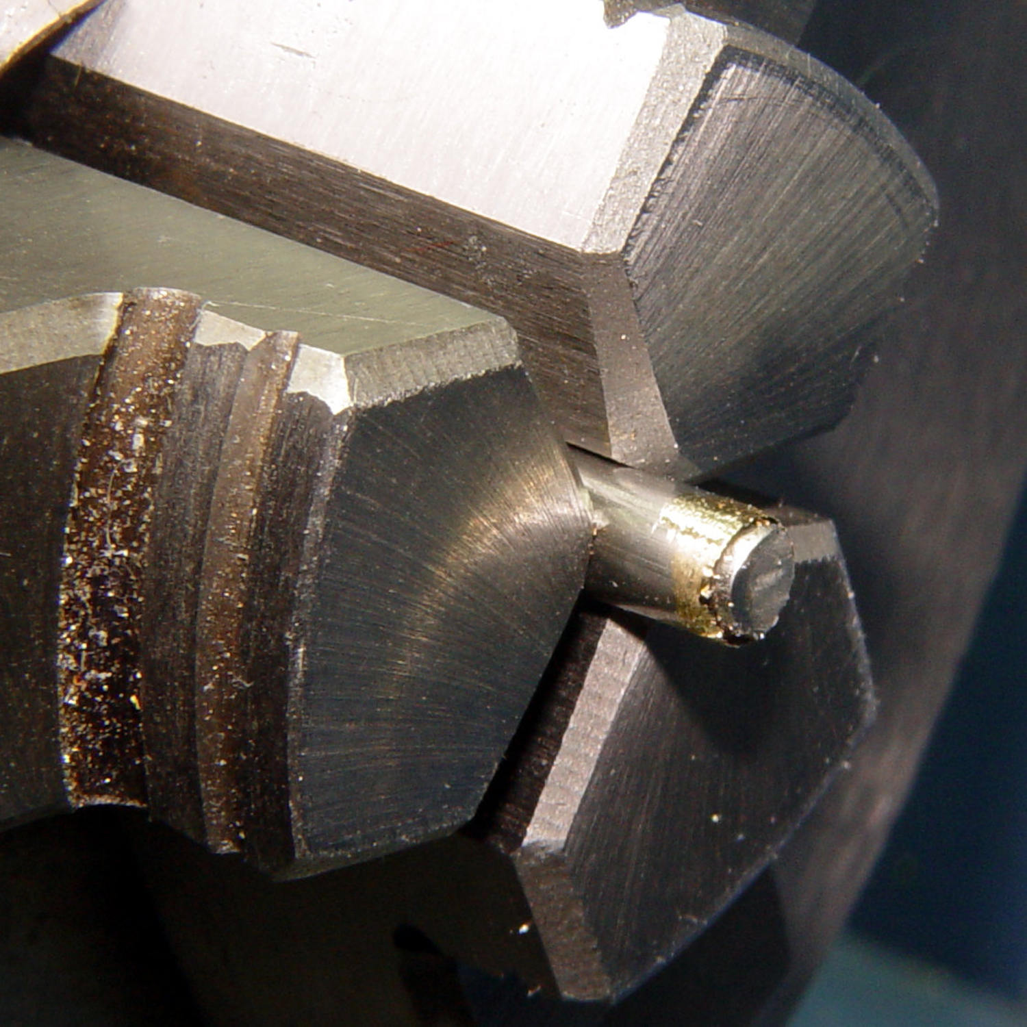
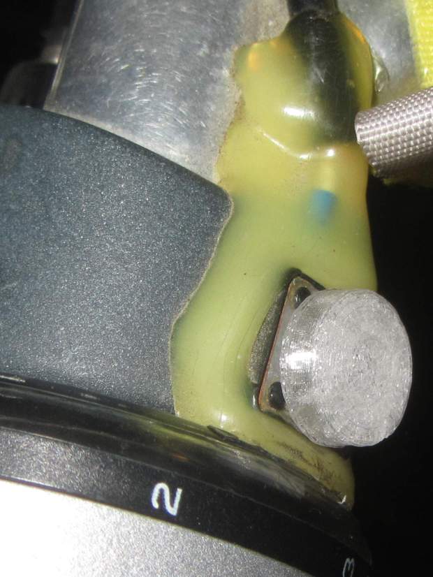
In the process, I discovered stainless steel nyloc nuts tend to gall on stainless steel screws:
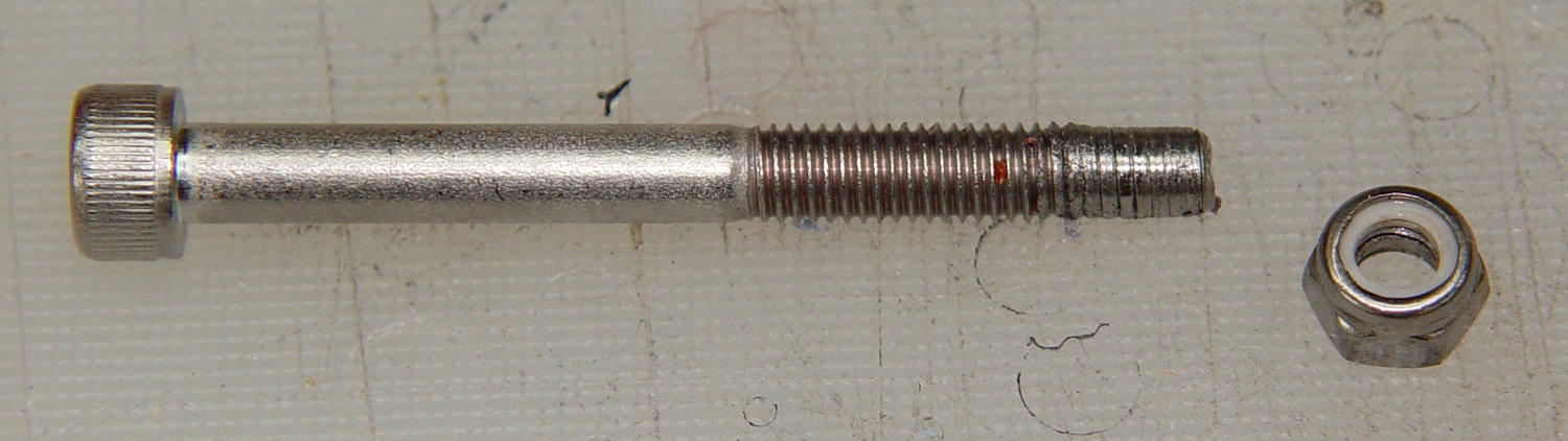
I lost a pair of screws + nuts before I got a clue and began adding a drop of machine oil to each screw before tightening the nuts. Haven’t had that problem with the 3 mm SS screws, so there’s always something new to learn.
With all the screws in place, the half-table becomes a rigid contraption:

The top looks like it’s suffering from severe barrel distortion, but it really started out looking that way:

The slat sides are all curved, except the far edge that was once in the middle of the table and now fits against the wall.
It may be slightly too short, but we can stack foam slabs on the top, probably held in place with cable ties.
Memo to Self: lube all the stainless steel screws!