Ed Nisley's Blog: Shop notes, electronics, firmware, machinery, 3D printing, laser cuttery, and curiosities. Contents: 100% human thinking, 0% AI slop.
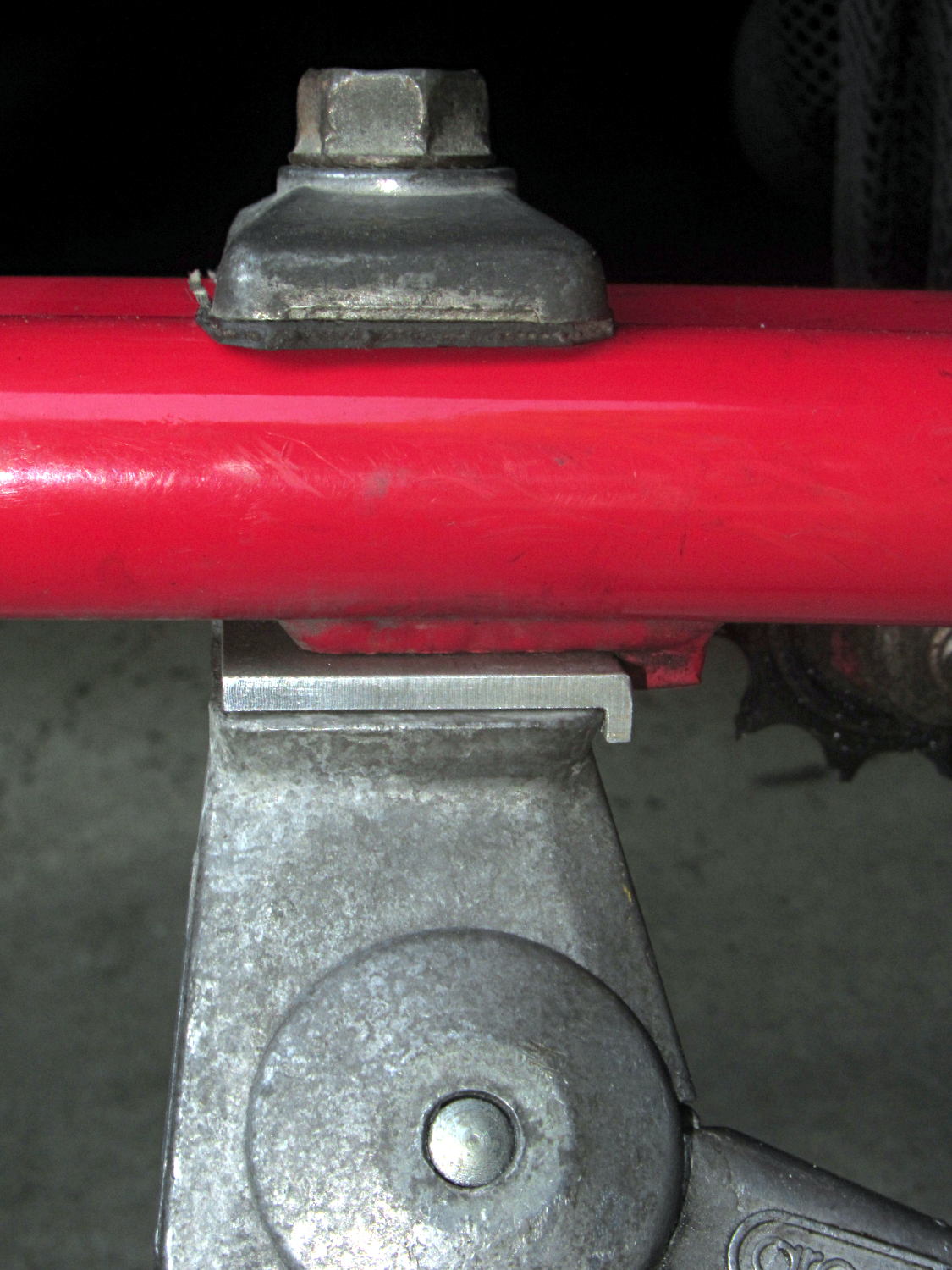
The venerable Greenfield kickstand on my Tour Easy doesn’t quite match the mounting plate under the frame, with the result that it can pivot just enough to make the bike tippy with a moderate load in the rear panniers. I’ve carried a small block to compensate for sloping ground, but I finally got around to fixing the real problem.
The solution turned out to be a spacer plate that fills the gap between the back of the kickstand casting and the transverse block brazed to the mounting plate:
Tour Easy kickstand adapter plate
That little lip is 2 mm wide, so it’s not off by much.
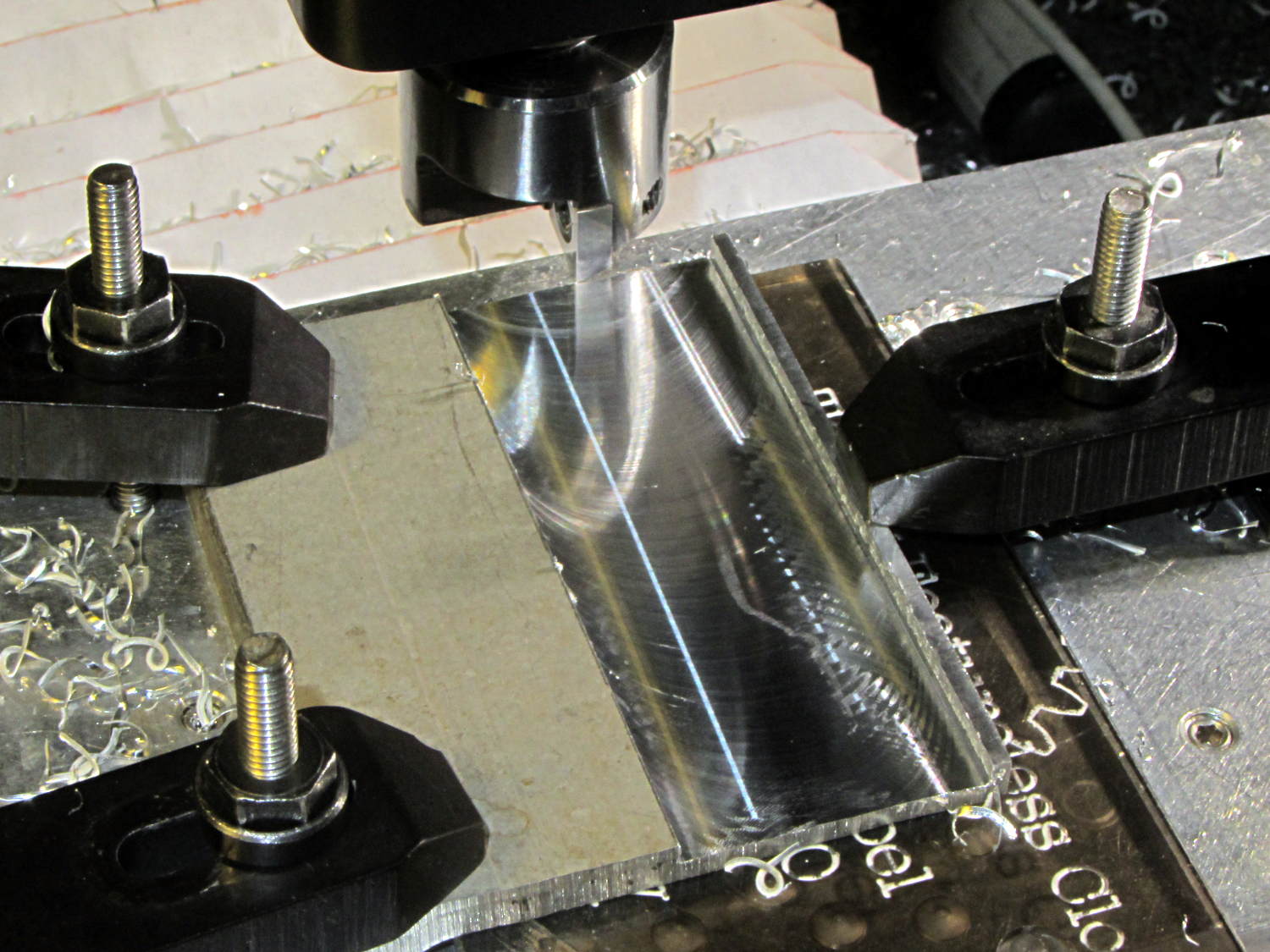
The aluminum came from a Z-shaped post that contributed its legs to a previous project. I flycut the stub of one leg flush with the surface, then flycut a slot 2 mm from the edge:
Tour Easy kickstand adapter – flycutting recess
For no reason whatsoever, the width of that slot turned out exactly right.
Bandsaw along the left edge of the slot, bandsaw the plate to length, square the sides, break the edges, mark the actual location of the mounting plate hole, drill, and it’s done!
An identical Greenfield kickstand on Mary’s identical (albeit smaller) Tour Easy (the bikes have consecutive serial numbers) fits perfectly, so I think this is a classic case of tolerance mismatch.
This doesn’t happen very often, but, after a few road trips and some jostling around, the M2’s platform was definitely out of alignment: the first layer came out generally too thin, with the X-Y+ quadrant very much too thin.
I tried a quick and dirty adjustment that didn’t produce meaningful results, then broke out the Starrett Taper Gauge and did it right.
Jog around measuring the height of the nozzle above the platform
Adjust screws to reduce variation
Change Z offset in startup G-Code
Run off a few test patterns to get the platform heated
Measure actual thickness
Change Z offset to get the right answer
Done!
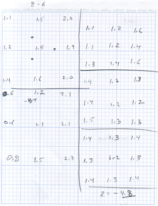
This progression of cold measurements, read top-to-bottom, left column first, shows the observed nozzle height above the platform around the edges and at the center:
M2 Platform Leveling Progression – 2014-06-30
The final measurements seem to indicate the glass plate is 0.2 mm convex in the center, but I wouldn’t trust the measurements to that level of accuracy. It’s probably bowed upward, but it’s certainly close enough.
The cold measurements suggest that the Z offset should be -4.80 mm, but the measurements on the hot platform with actual extrusion threads showed that -4.50 mm produced the correct thicknesses.
It’s not clear automating the movements would produce better or faster results than just manually jogging the nozzle around the platform, particularly since it happens only every few months.
This would be easier with the Z offset stored in the EEPROM and some modified startup G-Code to retrieve it.
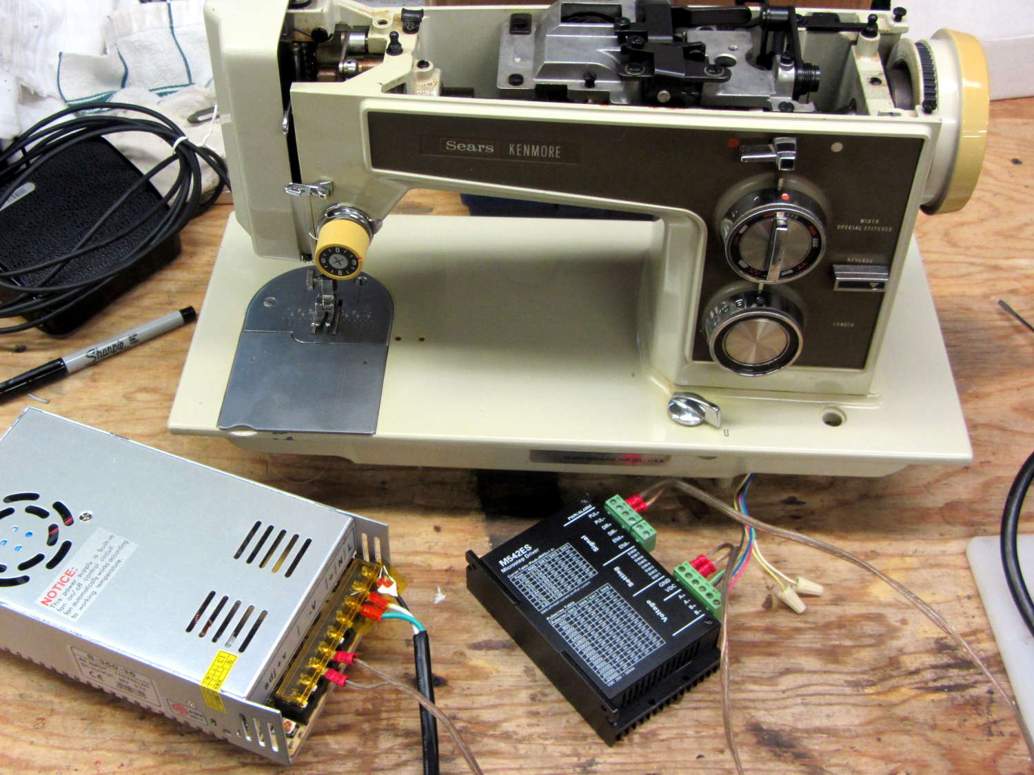
Having a NEMA 23 stepper fit almost exactly into the spot vacated by the sewing machine’s AC motor was too good to pass up:
Kenmore 158 – NEMA 23 stepper – on adapter
So I wired a power supply to an M542 stepper driver brick, connected the pulse output of a function generator to the brick’s STEP inputs, swapped motor leads until it turned the proper direction (CCW as seen from the shaft end), and turned the function generator knob:
Kenmore 158 – NEMA 23 stepper test
The object was to find the step frequency where the motor stalls, for various winding currents and supply voltages. The motor won’t have enough torque to actually stitch anything near the dropout speed, but this will give an indication of what’s possible.
With a 24 V DC supply and 1/8 microstepping (40 k step/s = 1470 RPM):
1.00 A = 11 k step/s
1.91 A = 44 k/s
2.37 A = 66 k/s
3.31 A = 15 k/s
With a 36 V DC supply and 1/8 microstepping:
1.91 A = 70 k/s
3.31 A = 90 k/s
With a 36 V DC supply and 1/4 microstepping (40 k step/s = 2900 RPM):
1.91 A = 34 k/s
2.37 A = 47 k/s
2.84 A = 47 k/s
3.31 A = 48 k/s
The motor runs faster with a higher voltage supply, which is no surprise: V = L di/dt. A higher voltage across the winding drives a faster current change, so each step can be faster.
The top speed is about 3500 RPM; just under that speed, the motor stalls at the slightest touch. That’s less than half the AC motor’s top speed under a similarly light load and the AC motor still has plenty of torque to spare.
90 k step/s at 1/8 microstepping = 11 k full step/s = crazy fast. Crosscheck: 48 k step/s at 1/4 microstepping = 12 k full step/s. The usual dropout speed for NEMA 23 steppers seems to be well under 10 k full step/s, but I don’t have a datasheet for these motors and, in any event, the sewing machine shaft provides enough momentum to keep the motor cruising along.
One thing I didn’t expect: the stepper excites howling mechanical resonances throughout its entire speed range, because the adapter plate mounts firmly to the cast aluminum frame with absolutely no damping anywhere. Mary ventured into the Basement Laboratory to find out what I was doing, having heard the howls upstairs across the house.
She can also hear near-ultrasonic stepper current chopper subharmonics that lie far above my audible range, so even if the stepper could handle the speed and I could damp the mechanics, it’s a non-starter for this task.
Given that the AC motor runs on DC, perhaps a brute-force MOSFET “resistive” control would suffice as a replacement for the carbon disk rheostat in the foot pedal. It’d take some serious heatsinking, but 100 V (or less?) at something under 1 A and intermittent duty doesn’t pose much of a problem for even cheap surplus MOSFETs these days.
That would avoid all the electrical and acoustic noise associated with PWM speed control, which counts as a major win in this situation. Wrapping a speed control feedback loop around the motor should stiffen up its low end torque.
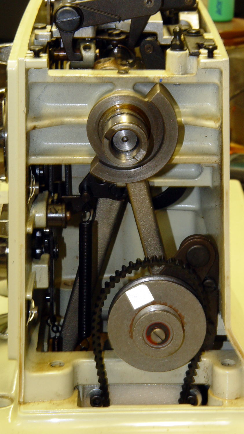
Fancy new sewing machines can stop with the needle either up (so you can remove the fabric) or down (to nail it in place while you rotate it). This requires sensing the needle position, which prompted me to spend far too long contemplating all the mechanical gadgetry driven by the motor.
As nearly as I can tell, the crank counterweight behind the handwheel produces the most unambiguous position reports. Here’s what it looks like with the needle down:
Kenmore 158 – main shaft counterweight
As you’d expect, with the shaft rotated exactly 180° from that point, the needle is up.
The inviting space just above the shaft provides room for the bobbin winder that engages a knurled ring on the back of the handwheel, but the lower space seems to be available. The counterweight sits about halfway into the back of the handwheel, so the sensors must look at the frame side of the counterweight.
Two adjacent sensors could detect the edge of the counterweight, which would be enough to uniquely identify both positions. If they were spaced across the lower-left edge in that picture:
01 = trailing edge = bottom dead center = needle down (as shown)
00 = open air = needle rising
10 = leading edge = top dead center = needle up
11 = solid steel = needle falling
Either sensor gives you one pulse per handwheel revolution and the combination gives you a quadrature output of both position and direction. The top speed of 1000 RPM produces 17 Hz square waves.
An additional pulse/rev sensor on the motor shaft would give better control over the motor speed, as the handwheel runs at 1/10 the motor speed with belt slip built right in. Figure 10 kRPM → 170 Hz pulses.
From a cold start, you know the shaft angle to within a bit under 180°. If the motor can turn in both directions (as would a stepper or DC motor), you can always move the needle upward. If it turns only forward (as does the AC motor) and the needle is falling, then you probably don’t want to move the motor until you get a button push indicating that all fingers are clear.
A pair of Hall effect sensors might suffice to detect that big hunk of steel, perhaps with a pair of teeny magnets glued to the face or a magnetic circuit closed by the counterweight.
During one of my recent presentations, somebody asked about the accuracy of 3D printed parts, which reminded me of another member of Coasterman’s Essential Calibration Set: the perimeter width/thickness test block. Back in the day, calibrating the extruder meant getting the actual ratio of the thread width to its thickness to match the ideal value you told Skeinforge to use; being a bit off meant that the final dimensions weren’t quite right.
But when I got it right, the Thing-O-Matic printed a test block with considerable success, despite the horrible retraction zittage:
Perimeter Calibration Block – yellow 1.10 rpm 0.33 0.66 mm
Alas, feeding the STL to Slic3r showed that it was grossly non-manifold, and none of the automated repair programs produced good results. Turns out it’s an STL created from a Sketchup model, no surprise there, and the newer slicers seem less tolerant of crappy models.
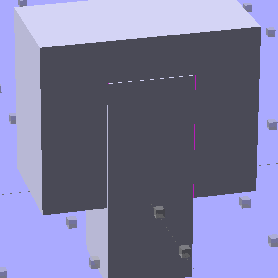
Sooo, here’s a new version built with OpenSCAD:
Fit Test Blocks – build view
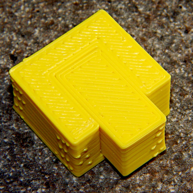
You get three blocks-and-plugs at once, arranged in all the useful orientations, so you can test all the fits at the same time. They come off the platform about like you’d expect:
Fit test blocks
I tweaked the code to make the plugs longer than you see there; the short ones were mighty tough to pry out of those slots.
I ran the plugs across a fine file to clean the sides, without removing any base material, and the plugs fit into the slots with a firm push. I’d do exactly the same thing for a CNC milled part from the Sherline, plus breaking the edges & corners.
The plugs doesn’t fit exactly flush in the recesses for the two models on the right side of that first image, because the edges and corners aren’t beveled to match each other. It’s pretty close and, if it had to fit exactly, you could make it work with a few more licks of the file. The left one, printed with the slot on the top surface, fits exactly as flush as the one from the Thing-O-Matic.
Of course, there’s a cheat: the model allows 0.1 mm of internal clearance on all sides of the plug:
Fit Test Block – show view
The outside dimensions of all the blocks and plugs are dead on, within ±0.1 mm of nominal. You’d want to knock off the slight flange at the base and bevel the corners a bit, but unless it must fit inside something else, each object comes off the platform ready to use.
Feel free to dial that clearance up or down to suit your printer’s tolerances.
The OpenSCAD source code:
// Fit test block based on Coasterman's perimeter-wt.stl
//	http://www.thingiverse.com/thing:5573
//	http://www.thingiverse.com/download:17277
// Ed Nisley - KE4ZNU - May 2014

Layout = "Show";

//- Extrusion parameters must match reality!
//  Print with 2 shells and 3 solid layers

ThreadThick = 0.20;
ThreadWidth = 0.40;

Protrusion = 0.1;			// make holes end cleanly

function IntegerMultiple(Size,Unit) = Unit * ceil(Size / Unit);

//----------------------
// Dimensions

Clearance = 0.1;

PlugSize = [10.0,10.0,25.0];
BlockSize = [25.0,13.0,20.0];

PlugOffset = 10.0;

//----------------------
// Useful routines

module ShowPegGrid(Space = 10.0,Size = 1.0) {

  RangeX = floor(100 / Space);
  RangeY = floor(125 / Space);

	for (x=[-RangeX:RangeX])
	  for (y=[-RangeY:RangeY])
		translate([x*Space,y*Space,Size/2])
		  %cube(Size,center=true);

}

module Block() {
	difference() {
		translate([0,0,BlockSize[2]/2])
			cube(BlockSize,center=true);
		translate([0,PlugSize[1] - PlugSize[1]/2 - BlockSize[1]/2,-PlugOffset])
			Plug(Clearance);
	}
}

module Plug(Clear = 0.0) {
	minkowski() {
		translate([0,0,PlugSize[2]/2])
			cube(PlugSize,center=true);
		if (Clear > 0.0)
			cube(Clear,center=true);
	}
}

//----------------------
// Build it

ShowPegGrid();

if (Layout == "Block")
	Block();

if (Layout == "Plug")
	Plug();

if (Layout == "Show") {
	Block();
	translate([0,PlugSize[1] - PlugSize[1]/2 - BlockSize[1]/2,-PlugOffset])
		Plug();
}

if (Layout == "Build") {
	Block();
	translate([0,-15,0])
		Plug();

	translate([-30,0,0]) {
		translate([0,-BlockSize[1]/2,BlockSize[1]/2])
			rotate([-90,0,0])
				Block();
		translate([-PlugSize[2]/2,-15,PlugSize[0]/2])
			rotate([0,90,0])
				Plug();
	}

	translate([30,0,0]) {
		translate([0,0,BlockSize[2]])
			rotate([180,0,180])
				Block();
		translate([-PlugSize[2]/2,-15,PlugSize[1]/2])
			rotate([90,0,90])
				Plug();
	}

}
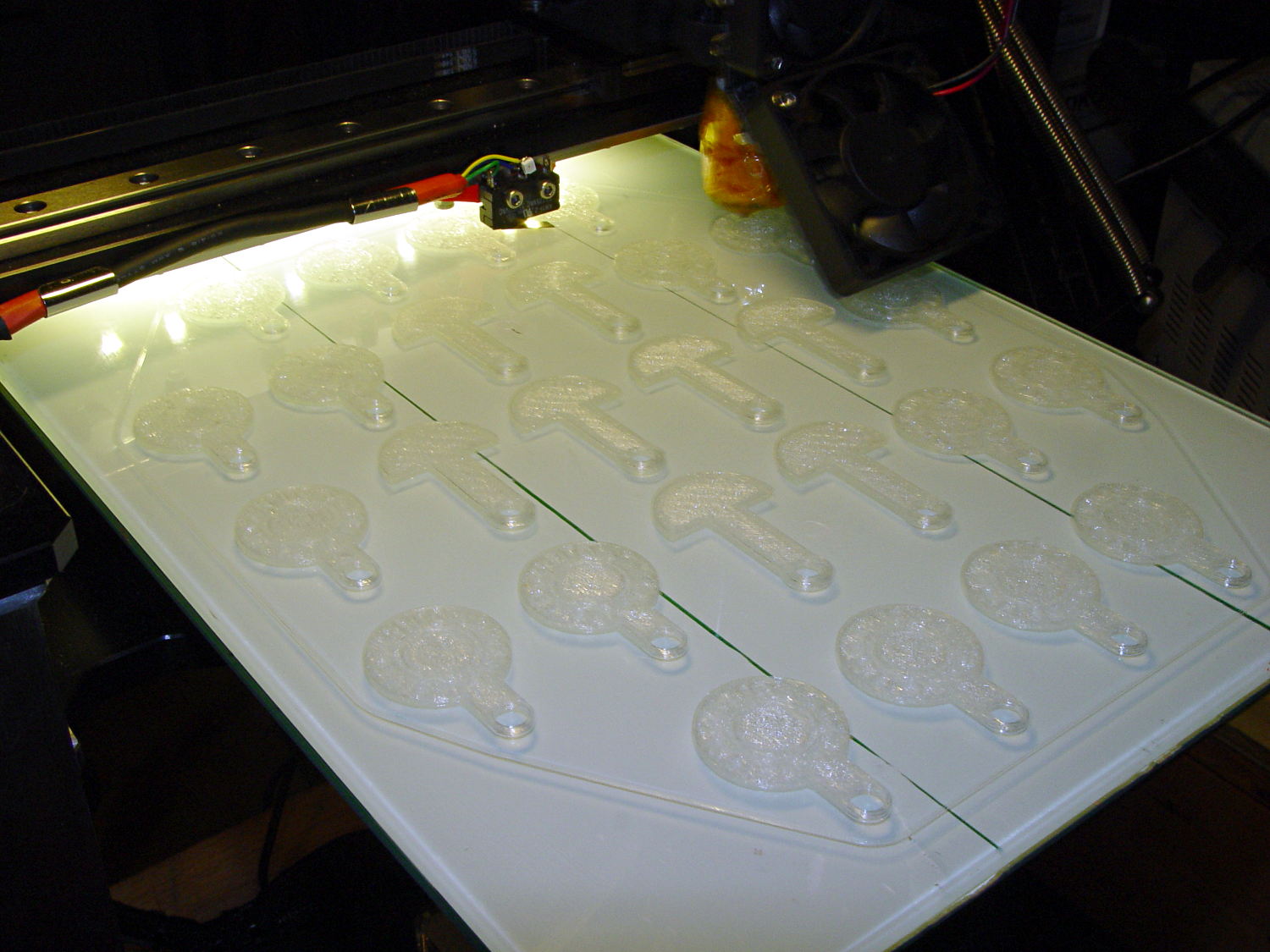
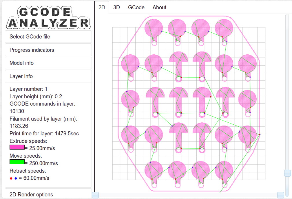
It turns out that an array of Cart Coins and Cart Releasers make a fine thickness test pattern and become useful tchotchkes when you’re done:
Cart Coins – printing
They’re a bit easier to see in the digital realm:
Cart Coins – platform layout – layer 1
The trick is that they’re both eight layers thick at 0.20 mm/layer. With the platform aligned exactly right, all the objects should measure exactly 1.60 mm thick.
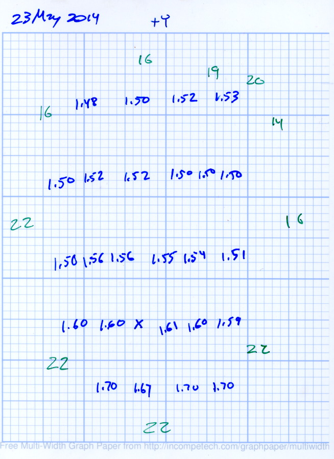
The blue numbers give the thickness measured across the stem, just above the hole, on each object:
Platform Leveling – Initial
The green numbers are the skirt thickness: 22 = 0.22 mm.
The platform has a tilt of 0.20 mm from +Y to -Y and is just about perfect from -X to +X.
The M3x0.5 adjusting screws under the (improved) platform, seen from the front (-Y) end of the platform:
M2 – Improved HBP – bottom view
The silicone plugs inside the springs are slightly compressed, so the springs are only decorative. The platform is rigidly mounted on the plugs, with only very slight compliance, and I haven’t leveled the platform in a few months.
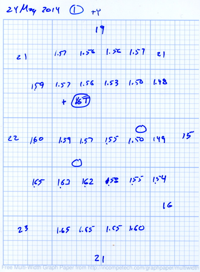
Tightening the “north” adjusting screw by 1/6 turn lowered the +Y end of the plate by about 0.05 mm and tilted the +X side slightly higher:
Platform Leveling – Adjustment 1
The skirt thicknesses are now in blue, too.
Tightening the “north” screw an additional 1/6 turn and tightening the “east” screw 1/6 turn produced an almost perfect result:
Platform Leveling – Adjustment 2
The thicknesses don’t vary quite randomly, but I think further adjustments won’t make much difference: the total range is only 0.12 mm = 1.53 to 1.65 mm. That’s pretty close to the limit of my measurement ability on the plastic pieces.
Notice that the skirt thread, which should be exactly 0.2 mm thick all around, really isn’t. I’m going to see whether a two-layer-thick skirt measures a more consistent 0.40 mm.
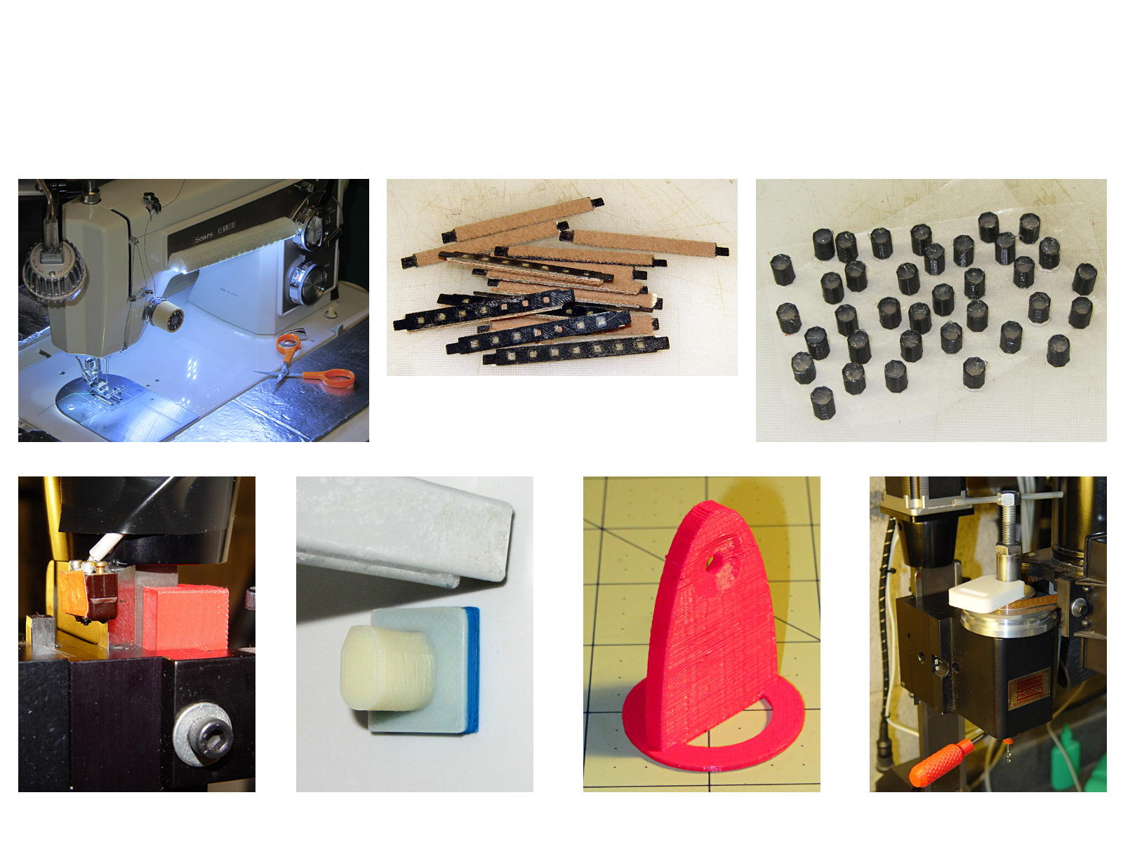
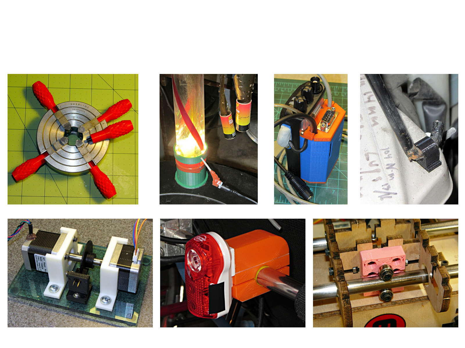
The whole reason I got a 3D printer in the first place was to make things that would otherwise be too difficult or tedious by hand or on a CNC mill. Most of the things I make look like brackets and I don’t do sculptures … this stuff solves problems!
Being able to go from “I need a part shaped like that” to holding the thing in my hand a few hours (or, for complex designs, days) later is empowering. Being able to adjust a dimension by changing the source code and “recompiling” to get a new part is wonderful.
These five slides from the presentation show my answers to the question “Why would anyone want a 3D printer?” Clicky for more dots.
Things I Designed – 1Things I Designed – 2Things I Designed – 3Things I Designed – 4Things I Designed – 5