The Smell of Molten Projects in the Morning

Ed Nisley's Blog: Shop notes, electronics, firmware, machinery, 3D printing, laser cuttery, and curiosities. Contents: 100% human thinking, 0% AI slop.

Category: Electronics Workbench

Electrical & Electronic gadgets

  • Juki TL-2010Q Needle LEDs: Installed!

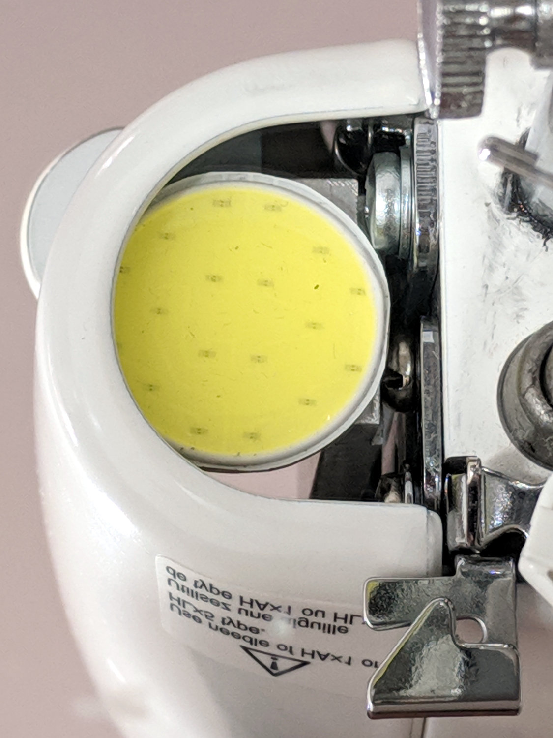
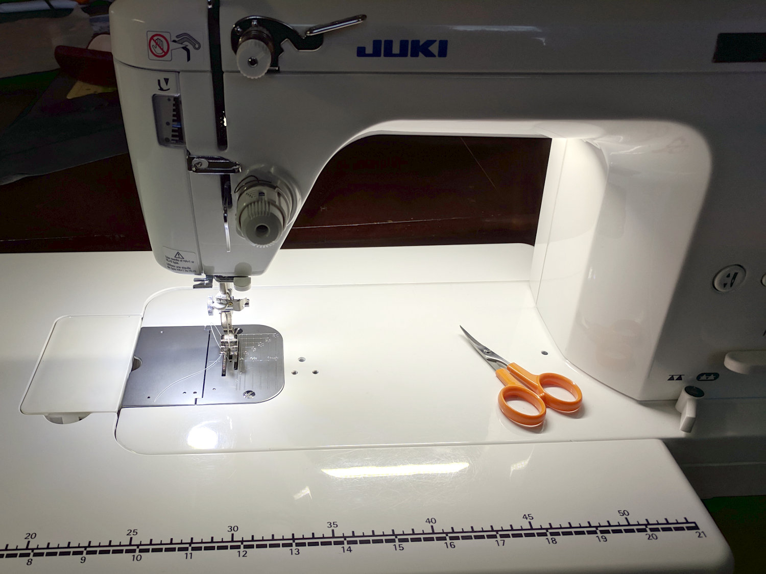
    The combined illumination from the COB LED bar on the rear of the arm and the (renewed) COB LEDs over the needle does a pretty good job of lighting up the work area:

    Juki TL-2010Q Needle LEDs - cloth illumination
    Juki TL-2010Q Needle LEDs – cloth illumination

    That’s a staged shot with a quilt square from the top of the pile. You’d (well, Mary’d) sew along the lines, not across a finished square.

    The remaining deep shadows under the foot require an LED with an imaging lens on a gooseneck; precise piecing requires feeding fabric into the needle with alignment exactly where those shadows fall.

    The light levels look harsh and shadowy on the bare base:

    Juki TL-2010Q Needle LEDs - front
    Juki TL-2010Q Needle LEDs – front

    The shadow extending leftward from the needle comes from the arm’s shadow of the rear LED bar. The hotspot specular reflections of both LED arrays aren’t quite as glaring in real life, but a matte surface finish would be better.

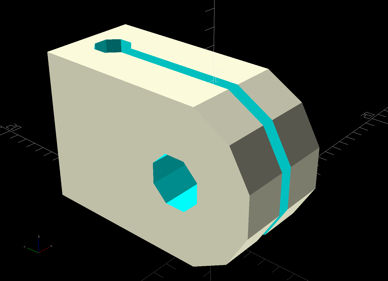
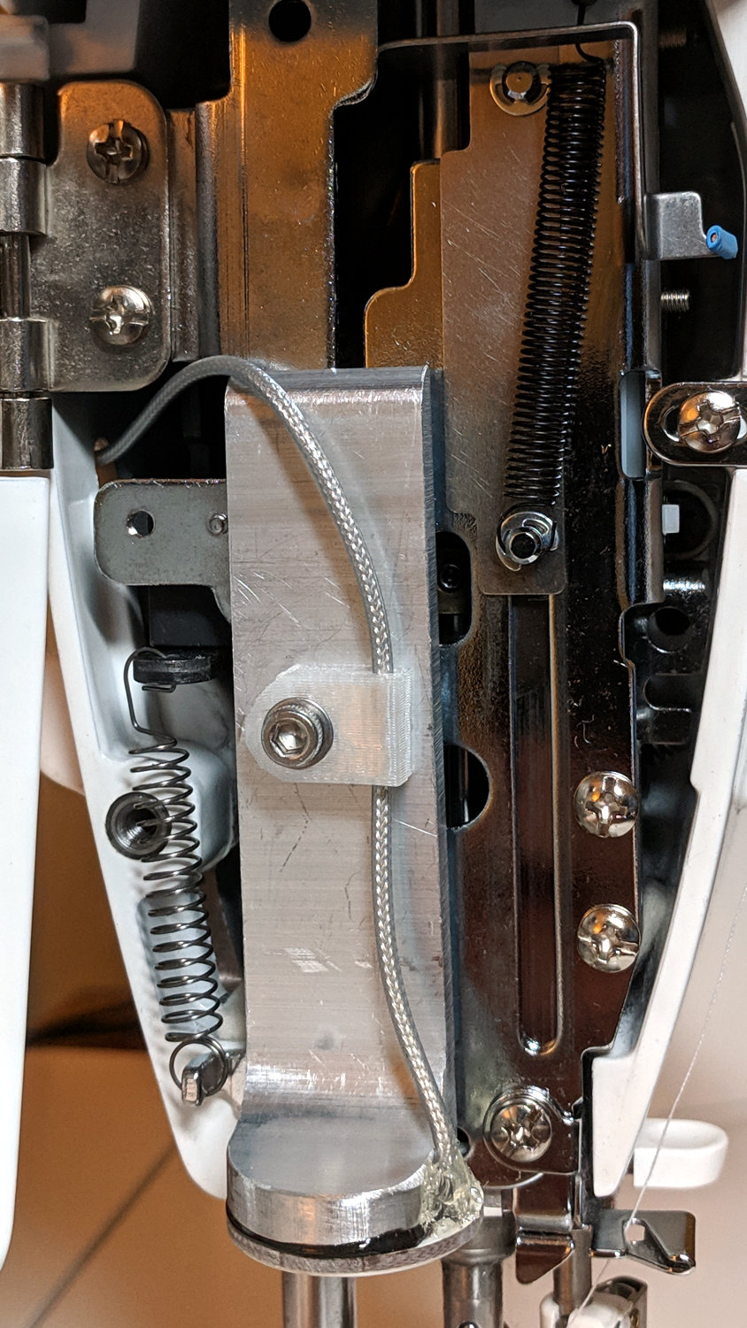
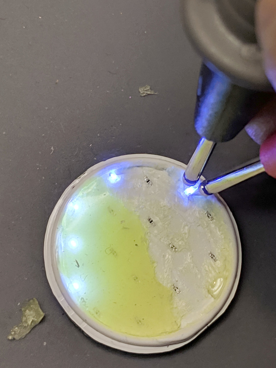
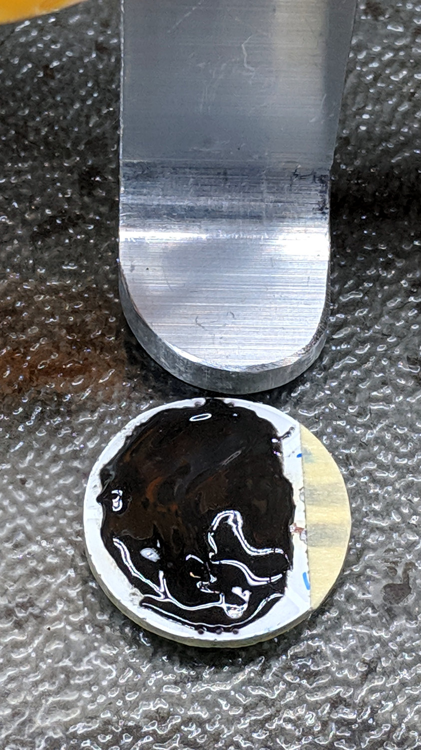
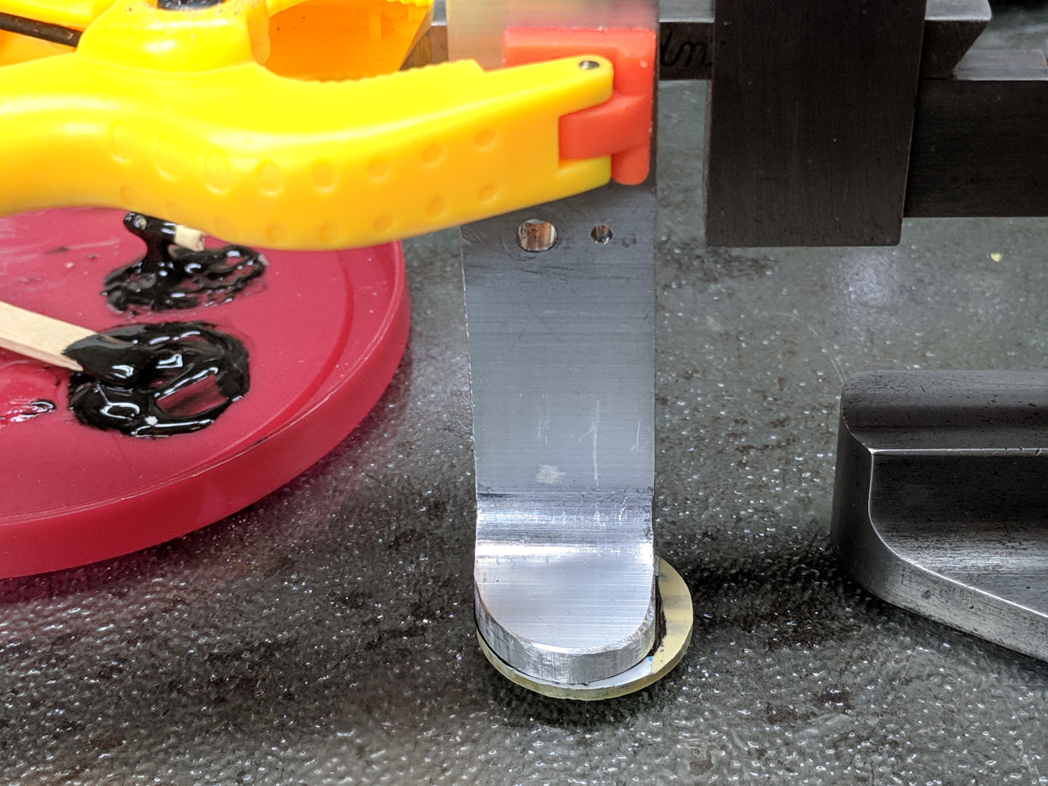
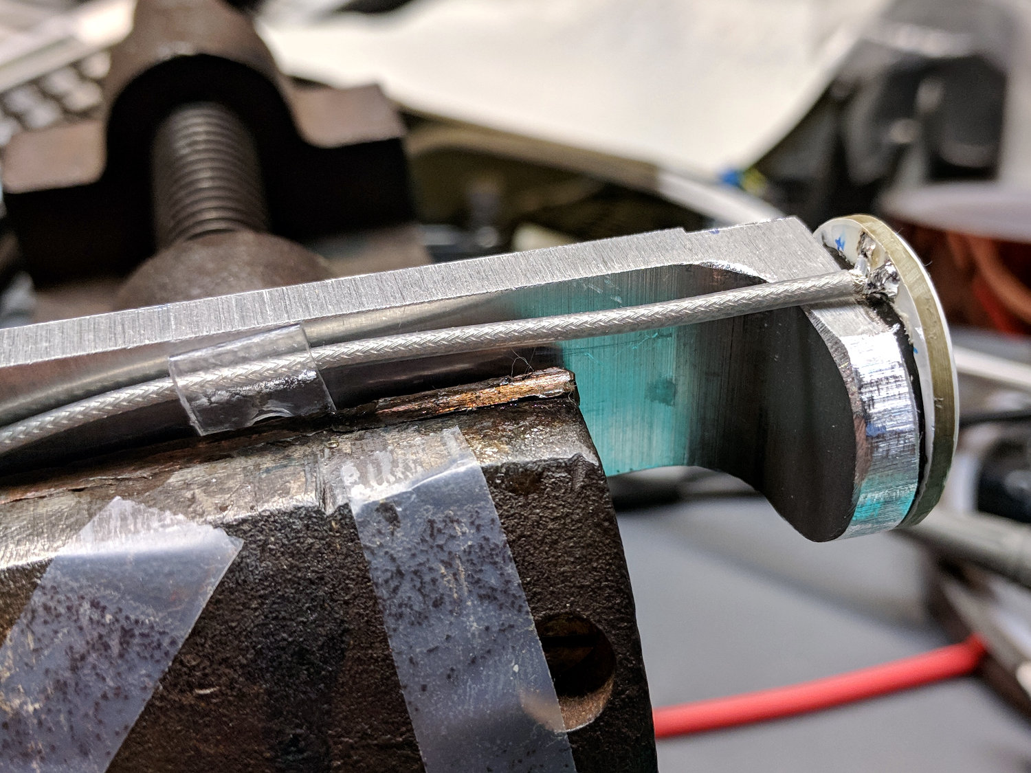
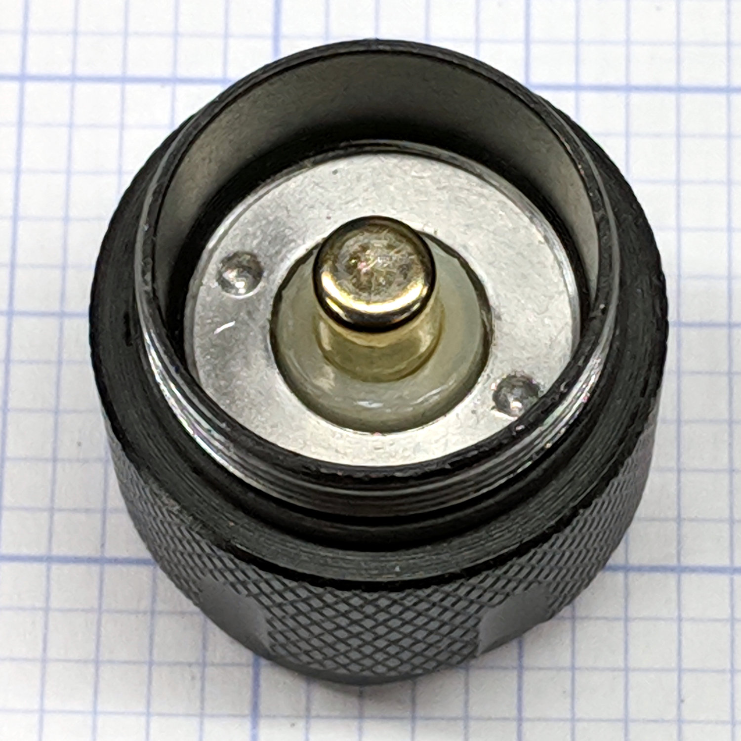
    The needle LEDs sit on the bottom of the heatsink inside the endcap:

    Juki TL-2010Q Needle LEDs - installed
    Juki TL-2010Q Needle LEDs – installed

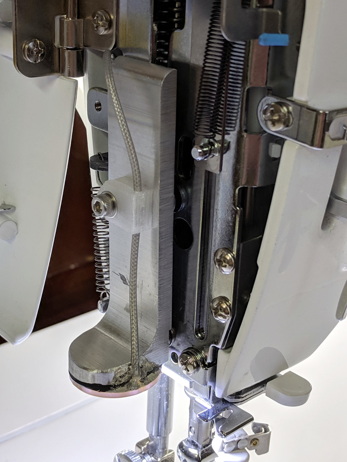
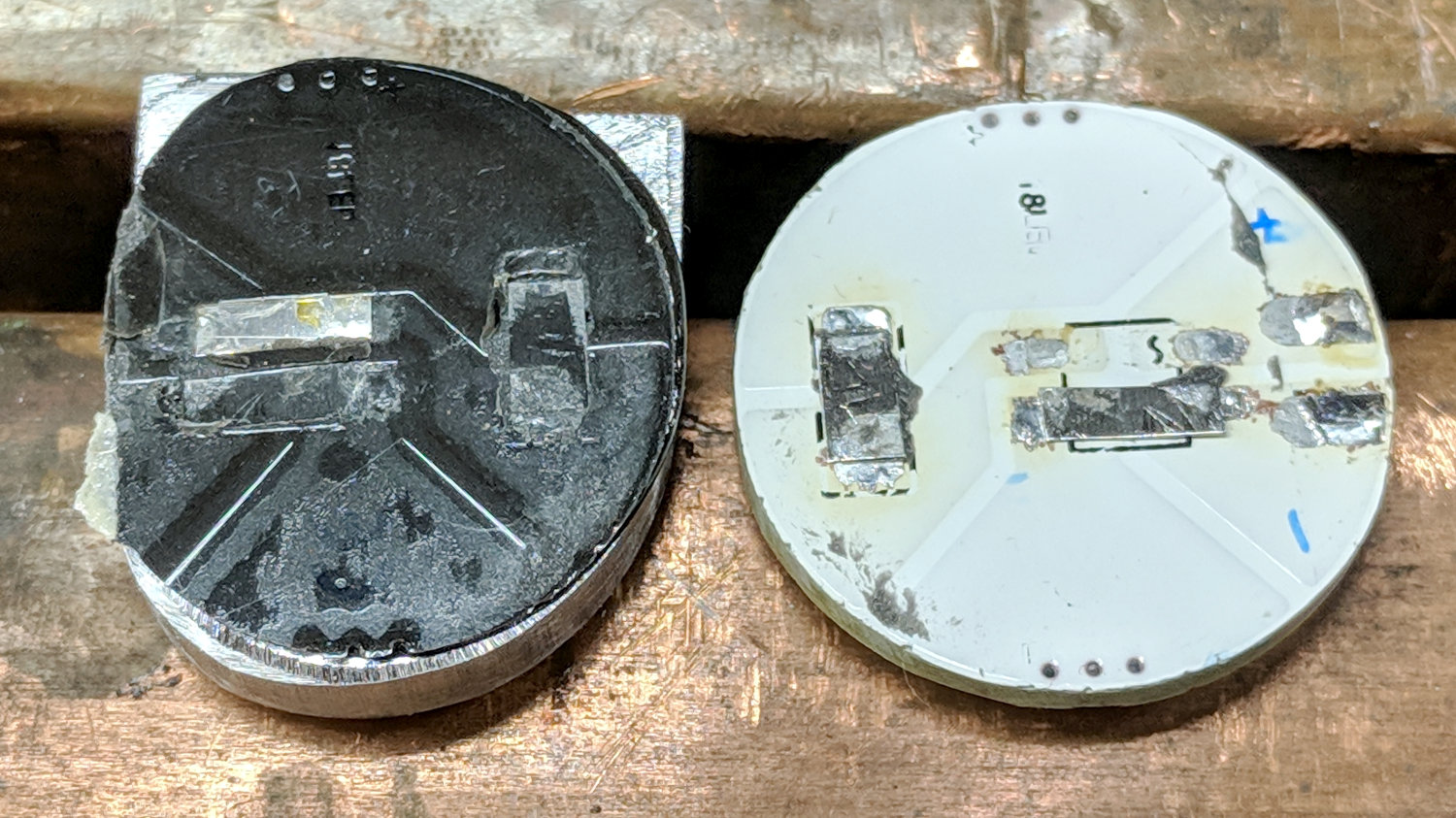
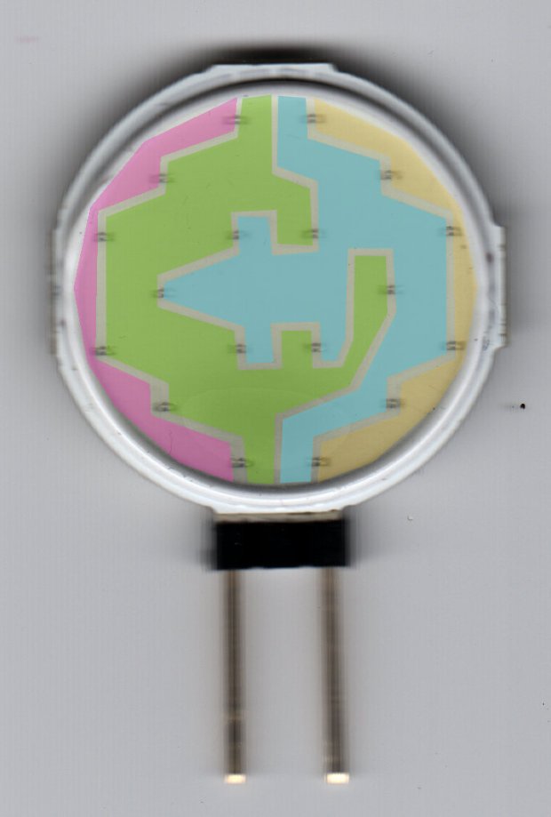
    The COB LED PCB has a weird pink tint, perhaps due to the silicone filter passing all the yellow and blue light downward, with red light reflected into the PCB.

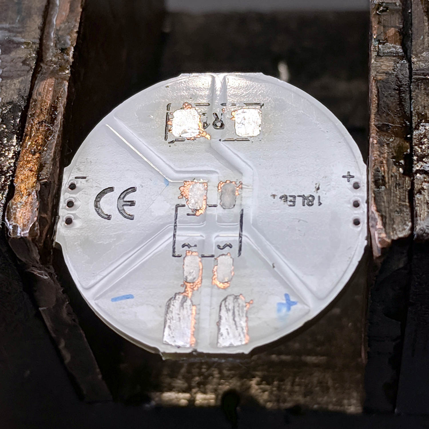
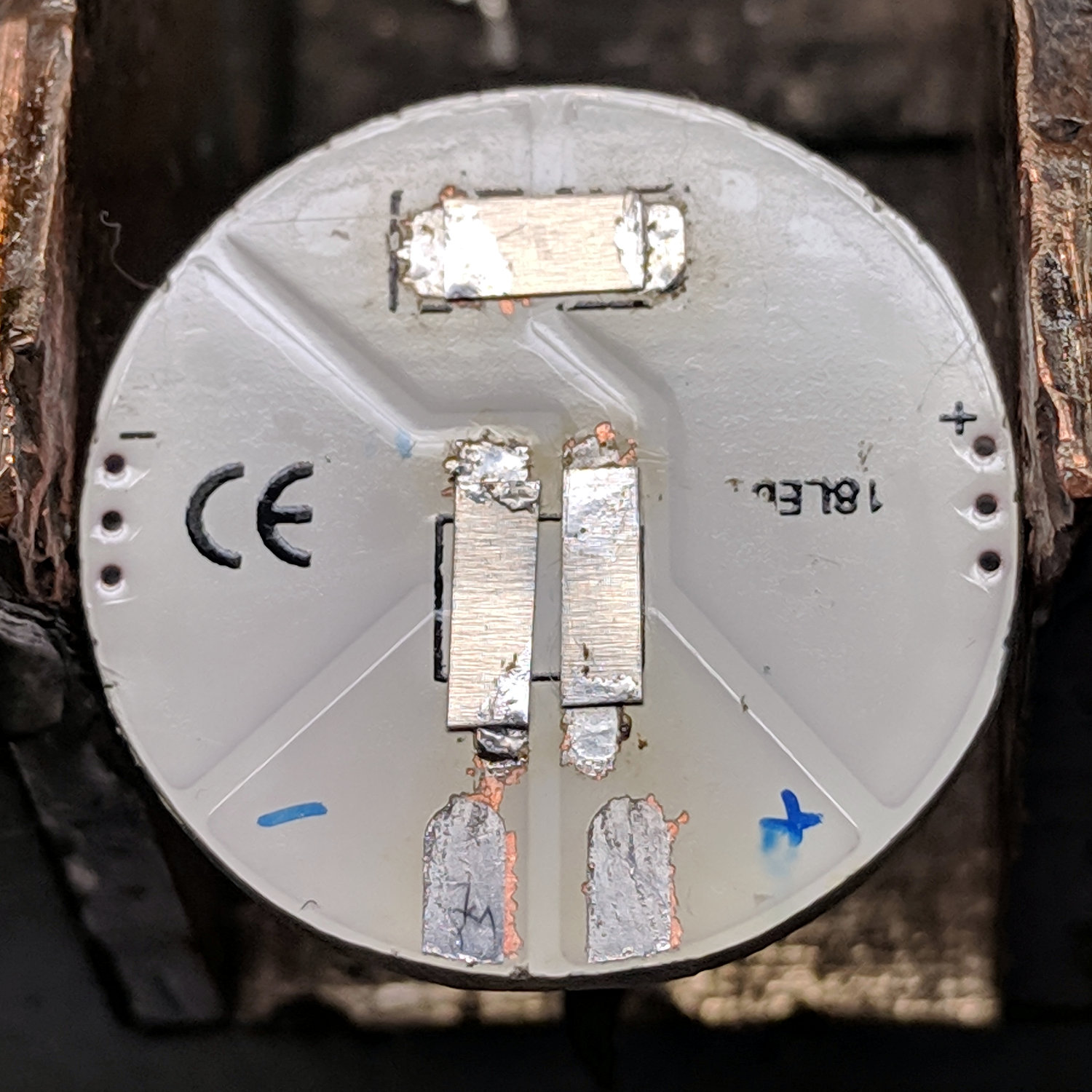
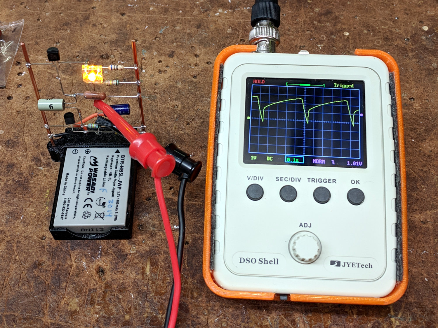
    After one iteration, I settled on a 20 Ω 1 W ballast resistor:

    Juki TL-2010Q Needle LEDs - ballast resistor
    Juki TL-2010Q Needle LEDs – ballast resistor

    It drops 3.6 V to provide 180 mA of needle LED current and dissipates 640 mW, with the LEDs burning about 1.5 W to raise the heatsink just above room temperature. The extrusion on the rear arm is pleasantly warm and the resistors seem happy enough.

    Looks good to us and it’s much much much better than the feeble Juki needle LED.

  • Juki TL-2010Q Needle LEDs: Simple Cable Clip

    A straightforward cable clip:

    TL-2010Q Needled COB LED - cable clip
    TL-2010Q Needled COB LED – cable clip

    It looks better than the previous hack bent from a snippet of PET clamshell:

    Juki TL-2010Q Needle LEDs - cable clip
    Juki TL-2010Q Needle LEDs – cable clip

    Ream out the holes with suitable drills, clean out the slot using Tiny Bandsaw™, and it’s all good.

    In retrospect, the slot isn’t worth the effort, because it doesn’t open wide enough to admit the cable and doesn’t provide any clamping force; a simple block with two holes would do as well. If the heatsink didn’t already have a 3 mm screw in play, I’d use an adhesive-backed clip from the early Kenmore LEDs.

    The OpenSCAD source code isn’t much to look at:

    //-----
    // Cable clip
    // Reoriented into build position, because we only need one
    
    ClipWall = 3*ThreadWidth;
    Clip = [15.0,10.0,CableOD + 2*ClipWall];
    
    module CableClip(CableOD = 2.0) {
    
    ClipSides = 4*3;
    ClipRadius = Clip.y/2;
    ScrewOD = 3.0;
    ClipOC = Clip.x - ClipRadius - CableOD/2 - ClipWall;
    
      translate([0,0,Clip.y/2])
        rotate([90,0,90])
          translate([0,0,0*Clip.z/2])
            difference() {
              union() {
                rotate(180/ClipSides)
                  cylinder(d=Clip.y/cos(180/ClipSides),h=Clip.z,$fn=ClipSides,center=true);
                translate([ClipRadius,0,0])
                  cube([Clip.x - ClipRadius,Clip.y,Clip.z],center=true);
              }
              translate([0,0,-(Clip.z/2 + Protrusion)])
                rotate(180/8)
                  PolyCyl(ScrewOD,Clip.z + 2*Protrusion,8);
              rotate([90,0,0])
                translate([ClipOC,0,-Clip.y])
                  rotate(180/8)
                  PolyCyl(CableOD,2*Clip.y,8);
              translate([ClipOC - Clip.x/2,0,0])
                cube([Clip.x,2*Clip.y,2*ThreadWidth],center=true);
            }
    }
    

  • COB LED Autopsy

    The intent was to wire the “5 W” COB LED to the 12 VDC supply grafted on the Juki TL-2010Q, through a suitable resistor around 18 Ω. Unfortunately, the next morning I managed to run 12 V directly to the LEDs, which produced an astonishingly bright flash of blue-white light and an opportunity for some post-mortem analysis.

    A sharp tap with a chisel popped the COB LED PCB off its heatsink:

    Destroyed COB LED - epoxy bond
    Destroyed COB LED – epoxy bond

    That’s a pretty nice thermal joint and ought to transfer as much heat as reaches the back surface. Mechanically, it yanked one of the nickel tabs right off the solder pads; obviously, I must now level up my soldering game.

    Scraping the yellow silicone filter off the PCB reveals the minuscule LEDs:

    Destroyed COB LED - excavated yellow silicone
    Destroyed COB LED – excavated yellow silicone

    You’ll recall they’re arranged in three series sets of six:

    Circular 12V COB 18 LED panel - copper layout
    Circular 12V COB 18 LED panel – copper layout

    Some probing revealed five of six LEDs in one set was still functional:

    Although a few other LEDs across the PCB survived, that’s not the way to bet when you run so much current through the poor things.

    Ah, well, that’s why I always buy a few more parts than I really need …

  • Juki TL-2010Q Needle LEDs: Trial Fit

    Stripping the components from the back of a “5 W” COB LED gets it ready for action:

    G4 COB LED PCB - stripped
    G4 COB LED PCB – stripped

    Jumpering the pads with nickel strips harvested from various NiMH and lithium cells restores the original contact pads to service:

    Juki TL-2010Q Needle LEDs - COB LED jumpers
    Juki TL-2010Q Needle LEDs – COB LED jumpers

    A bit of bandsaw artistry produced a replacement for the OEM LED bracket:

    Juki TL-2010Q Needle LEDs - trial installation
    Juki TL-2010Q Needle LEDs – trial installation

    The epxoy bonding the LED to the heatsink happens a few paragraphs ahead in this story, but the view justifies it. The 2 mm hole just to the right of the 3 mm SHCS aligns the heatsink to a pin in the machine’s frame, ensuring it doesn’t twist around under vibration.

    The view from below (in a mirror on the machine’s bed) shows the COB LED just barely fits in the opening:

    Juki TL-2010Q Needle LEDs - trial fit
    Juki TL-2010Q Needle LEDs – trial fit

    I screwed the bare heatsink into the Juki, applied double-stick tape to the COB LED, aligned LED with opening, and stuck it in place. Back in the shop, I traced around the LED to figure out what part of the heatsink needed removing, introduced it to Mr Disk Sander, and contoured it to match the LED.

    Clean everything with denatured alcohol, put the heatsink on a glass plate, and clamp it to the height gauge:

    Juki TL-2010Q Needle LEDs - heatsink alignment
    Juki TL-2010Q Needle LEDs – heatsink alignment

    Butter up the LED PCB with JB Kwik epoxy, having previously masked the contact pads (with masking tape!) to prevent oopsies:

    Juki TL-2010Q Needle LEDs - epoxy on COB LED
    Juki TL-2010Q Needle LEDs – epoxy on COB LED

    Raise the height gauge, align LED & heatsink, lower height gauge to squish epoxy into an even layer, raise slightly to ensure the aluminum heatsink doesn’t short the nickel strips, and fast forward a few hours:

    Juki TL-2010Q Needle LEDs - heatsink curing
    Juki TL-2010Q Needle LEDs – heatsink curing

    Peel off the masking tape and solder a cable in place:

    Juki TL-2010Q Needle LEDs - cable installation
    Juki TL-2010Q Needle LEDs – cable installation

    The transparent doodad around the cable is a PET clamp snipped from a consumer electronics clamshell package, then punched and folded to suit. It didn’t work particularly well, so more rummaging will be required.

    Foreshadowing: all this went swimmingly and looks pretty good (in a techie sort of way), but I’ve been running a nasty cold (stipulated: there being no pleasant colds). Building While Stupid is never a good idea, as the part of your brain in charge of telling you you’re about to do something catastrophically wrong is the first thing to go.

    More to come …

  • Astable Multivibrator: DSO150 vs. Fast Blinky

    A bipolar transistor version of the astable multivibrator with a yellow Pirhana LED required absurdly large capacitors for a reasonable blink rate and, seeing as how I need a demo circuit for Show-n-Tells, it seemed a good candidate for a faster blink. I replaced a 100 µF cap with the 22 µF electrolytic cap from the other side, installed a 2 µF cap (which, judging from the lack of polarity indicators, may be a film cap) from the Squidwrench junk heap parts bin in its place, and hitched up the DSO150 because I brought it along:

    DSO150 with fast LED blinky
    DSO150 with fast LED blinky

    Worked the first time and caught it in mid-blink! [grin]

    The DSO150’s triggering remains a mystery, as it seems difficult to get a stable trace from a perfectly reasonable waveform. The scope didn’t trigger well on the astable’s original seconds-long pulses, perhaps due to a DC blocking cap in the triggering circuitry (whatever it may look like), but this waveform should be dead simple.

    Having gained a visceral understanding of why MOSFET astables produce better battery life, this bipolar transistor design is just a milestone along the way.

  • J5 Tactical Flashlight: Tailcap Switch

    Mashing the LED PCB into place didn’t entirely solve the weak beam problem, so I unscrewed the tailcap holding the switch on the other end of the body:

    J5 Tactical Flashlight - tailcap
    J5 Tactical Flashlight – tailcap

    Unscrewing the lock ring releases the switch assembly:

    J5 Tactical Flashlight - tailcap parts
    J5 Tactical Flashlight – tailcap parts

    I suspect the tab sticking out from the side of the switch doesn’t make / never made good contact with the aluminum tailcap body, but having gone this far there’s no reason to stop. The plastic housing around the spring-loaded brass battery contact pops off to reveal the actual switch:

    J5 Tactical Flashlight - switch contacts
    J5 Tactical Flashlight – switch contacts

    The long tab on the front of the switch sits under the spring, so that’s the negative battery contact. The LED current goes through:

    • battery negative to contact + spring
    • switch tab + moving contact + tab
    • tab to tailcap pressure fit
    • tailcap threads
    • front tube threads
    • LED pill to PCB
    • spring to battery positive

    So. Many. Aluminum. Joints.

    The switch body snaps apart to disgorge a remarkable number of parts:

    J5 Tactical Flashlight - tailcap switch parts
    J5 Tactical Flashlight – tailcap switch parts

    Nothing looked out of order, so I applied a thin layer of DeoxIT Red to all the contacting parts and reassembled everything.

    For the record, the switch’s internal parts have many plausible assembly sequences; the workable one goes a little something like this:

    J5 Tactical Flashlight - tailcap switch contacts
    J5 Tactical Flashlight – tailcap switch contacts

    Contrary to what you (well, I) might think, the switch is off when the central contact is pushed forward, away from the side contacts.

    I bent a slight angle into the tailcap contact (on the right in the picture) to make better / firmer contact with the tailcap body, cleaned all the threads with a cotton swab carrying a dab of DeoxIT, and screwed it all together.

    With everything back together, the beam seems bright and steady again. We’ll see how long it lasts.

  • J5 Tactical Flashlight: Loose PCB

    I’ve been using the J5 Tactical flashlight as a “walking light” on our walks around the neighborhood, because its bright white spot has definitely caused a few drivers to look up from their phones at the last moment and swerve away.

    Of late, however, it turned on with a weak light and operated erratically. Removing the lens and unscrewing the front end revealed one mmmm potential problem:

    J5 Tactical Flashlight - loose LED PCB
    J5 Tactical Flashlight – loose LED PCB

    It looks like they’re depending on the “gold” in cutaway plated-through holes to make electrical contact with the aluminum mount, then through the threads to the case. The PCB joint would work much better with consistent pressure all the way around its perimeter.

    I mashed the PCB into place with a machinists vise, but, given the number of problems I’ve had with J5 flashlights (one a QC reject), they’re on my Non-Preferred Vendor list; if I’m going to get junk, I may as well pay bottom dollar.