Ed Nisley's Blog: Shop notes, electronics, firmware, machinery, 3D printing, laser cuttery, and curiosities. Contents: 100% human thinking, 0% AI slop.
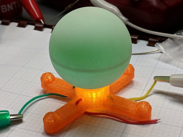
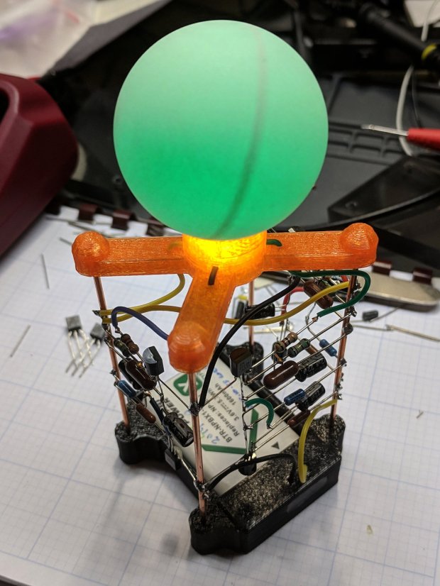
Because I planned to take my collection along to HV Open’s Mad Science Fair, I finally used a Round Tuit for some adhesive action.
The general plan was to punch a ring from double-sided tape, thusly:
Astable – Radome adhesive – poor surface
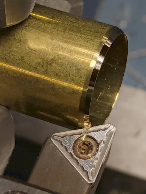
The OD required touching up the edge of a brass tube punch I’d made a while ago:
Astable – Radome adhesive – punch sharpening
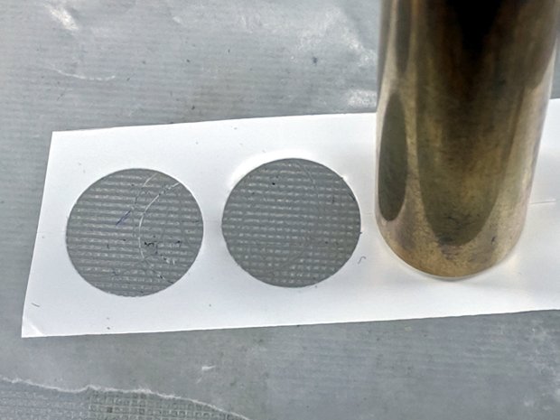
It worked exactly as expected:
Astable – Radome adhesive – punching
Unfortunately, the 3D printed spider’s “spherical” socket has such a rough surface that the adhesive had too few contact points to hold the ball in place.
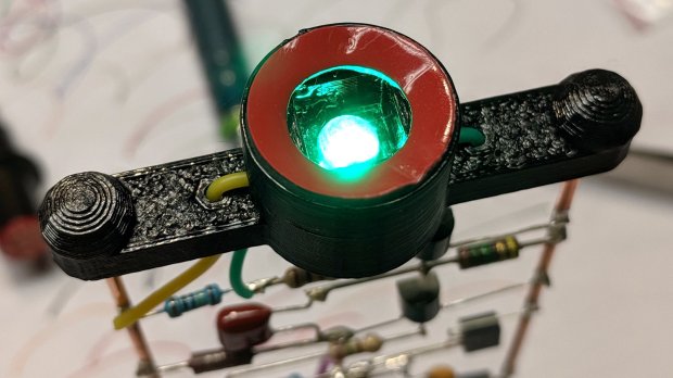
My fallback has become 3M outdoor-rated double-stick foam tape, so:
Astable – Radome adhesive – 3M foam tape
This leaves a small black ring visible between ball and socket. Recessing the foam tape by half its thickness should improve its ahem optics, although it’s probably not worth the effort with black PETG.
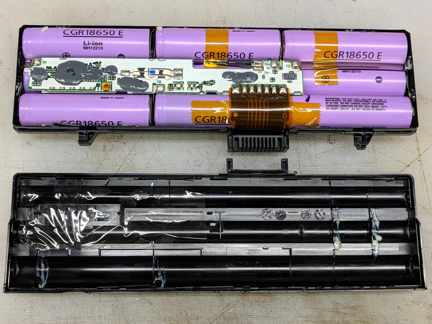
The battery pack on my ancient Dell E1405 laptop finally died, so I tore it apart to see what horrors might lurk within:
Dell UG679 Lithium Battery – teardown
The case snaps apart without too much effort, although the delicate single-use latches won’t survive the operation. These certainly didn’t, which didn’t bother me at all, as I already had a replacement battery on order.
One of the cells (in the front) seems to have leaked ever so slightly inside its wrapper:
Dell UG679 Lithium Battery – leaky cell
The three cells in that 3P section seem to have failed open: they pass no current at all.
The other pair of 3P slices, charged at 4.2 V with a 700 mA current limit until the current dropped under 10 mA, still have some life:
Dell UG679 3P sections
Perhaps recycling individual cells into LED glowies would be nice, as they have enough capacity remaining to run an Arduino for quite a while, and a 1S USB charger would make for a self-contained package.
As the basement’s fluorescent fixtures and lamps gradually die, I’ve been rewiring the fixtures for LED tubes, all bought from KEDSUM through Amazon. The first few batches looked like this:
Kedsum – good LED lamp
The most recent two batches seem cheapnified:
Kedsum – poor LED lamp
The tubes show similar changes, going from a stylin’ version to a simple cylindrical cap:
Kedsum vs Kedsun – tube end caps
The most recent carton label might lead you to think they’re counterfeits, but it could just be a simple typo:
Kedsum vs Kedsun – LED lamp carton
There’s absolutely no way to tell what you’re going to get from any vendor on Amazon (or anywhere else, for that matter), so there’s no point in returning them, but I’d hoped buying “the same thing” from “the same seller” would produce a consistent result.
Start by prying the recessed top panel off the case:
Ooma Telo 2 – upper case latches
Remove the circuit board to expose the tiny speaker, taking care not to rip the tiny wires out of the tiny connector:
Ooma Telo 2 – OEM speaker to PCB
You can’t measure a dead speaker, but it seems to be an 8 Ω unit.
The speaker sits in a rubber surround, with a foam rubber cushion against the PCB, tucked into a walled garden stiffening the case:
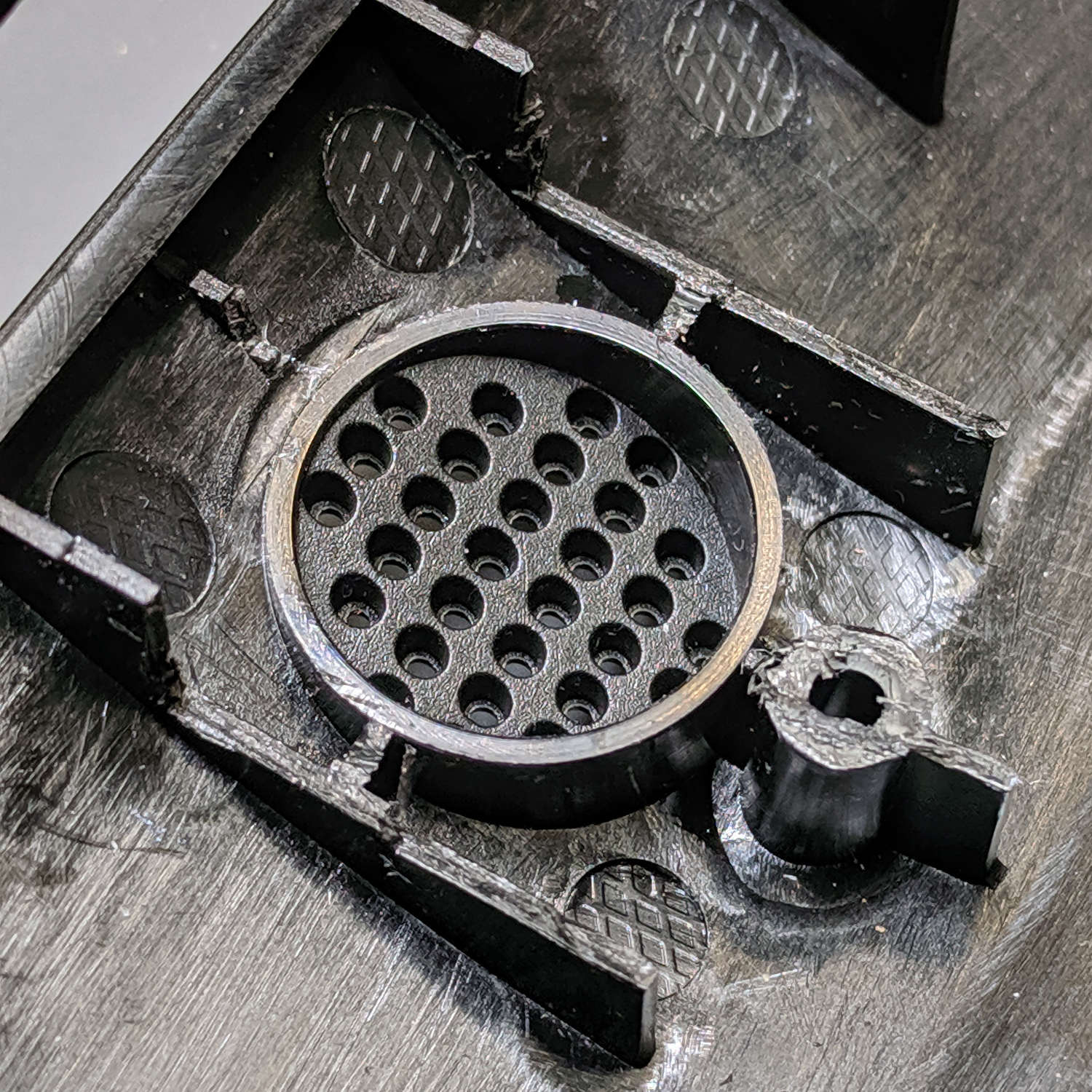
Ooma Telo 2 – speaker port
I don’t happen to have a tiny 8 Ω speaker, but I do have a bunch of small speakers (Update: 28 mm OD), so I bulldozed those walls with a flush cutting pliers and a bit of cussing to make room:
Ooma Telo 2 – modified speaker port
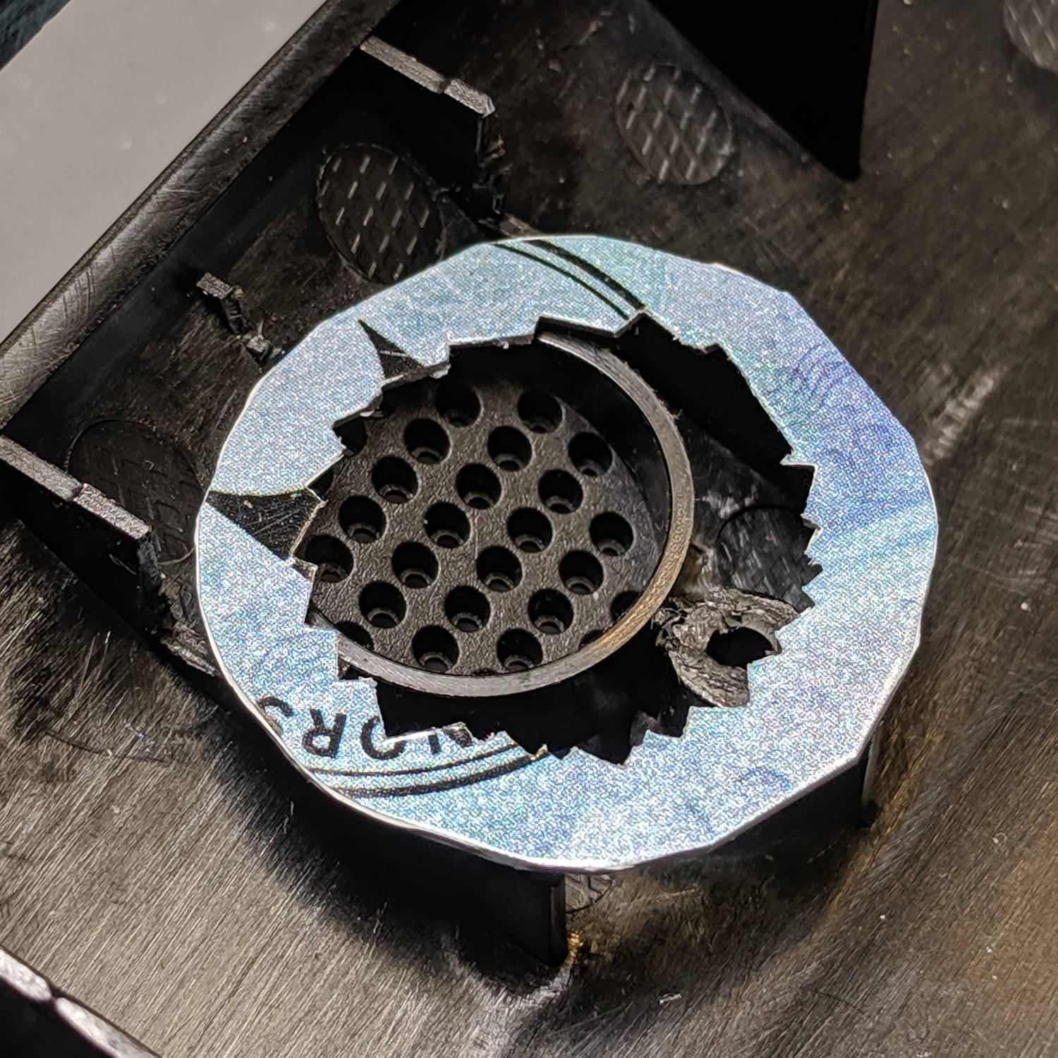
Nibble an adapter ring to match the rim of the new speaker, thereby routing the sound out those little holes, and hot-melt glue it in place:
Ooma Telo 2 – speaker adapter
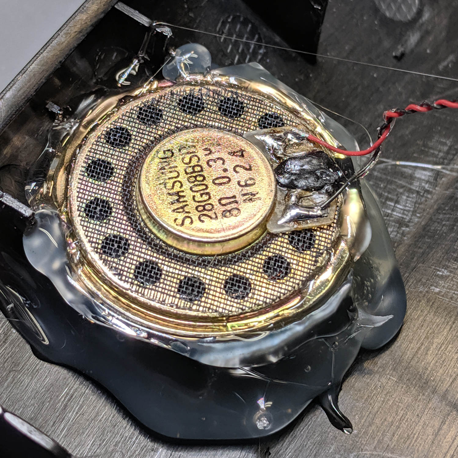
Hot-melt glue the new speaker in place atop the adapter, taking care to fill all the edges / cracks / crevices below it with an impenetrable wall of glop:
Ooma Telo 2 – replacement speaker installed
The sealing part turns out to be critical with these little speakers, because a leak from front to back will pretty much cancel all the sound from the cone.
Cut the wires off the old speaker, affix to the new one, replace the PCB, snap the case lid in place, and it sounds better than new.
Millions of transistors in those ICs, but Ooma can’t spec a good speaker? Maybe they should have used a bigger speaker to begin with; ya never know.
My landscape monitor, a six-year-old Dell U2711, died after a few days of flickering and failure-to-start. As you’d expect with any old electronics, particularlyfrom Dell, it’s the electrolyticcaps:
Dell U2711 Monitor – failed caps
All of the black-cased caps on the board had bulged cases:
Dell U2711 Monitor – failed FOAI cap – detail
They’re (allegedly) made by FOAI, for whatever that’s worth.
They’re not really capacitors any more:
Dell U2711 Monitor – 100 uF 5 ohm cap
I replaced all of them with cheap eBay caps to no avail. Spot-checking the other (“brown”) caps on the logic board showed they were still good, but the power supply board is firmly glued in place and I can’t get to the HV cap.
A new monitor arrived two days later and it’s all good again.
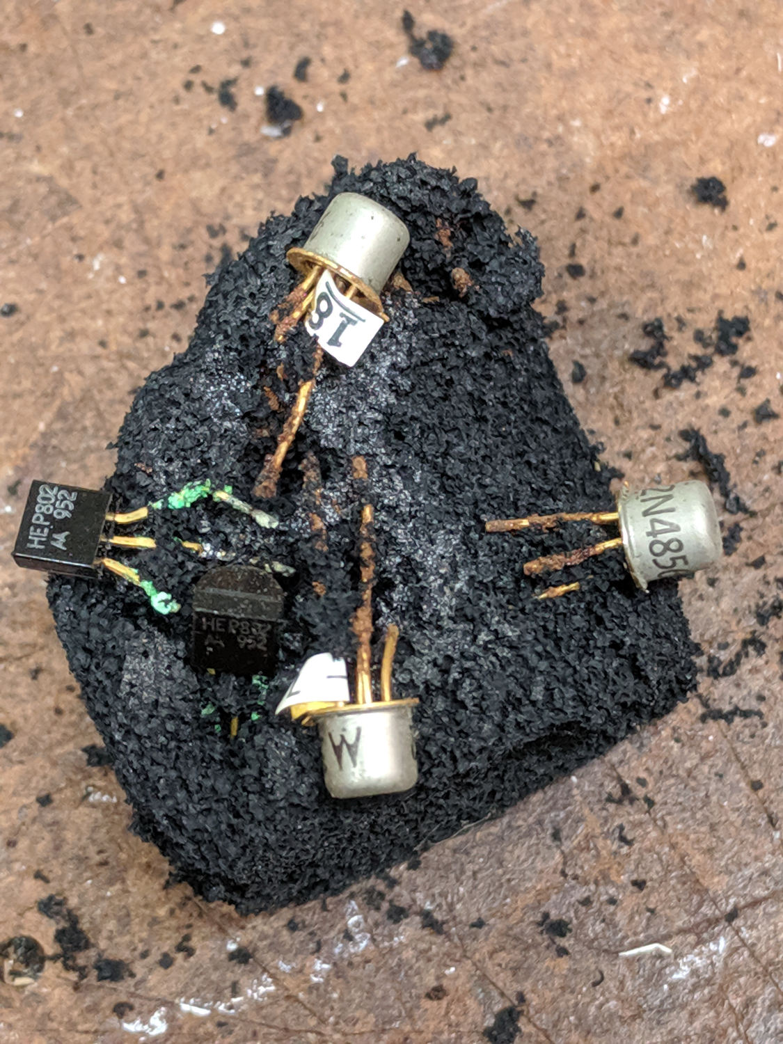
Why you shouldn’t use antistatic foam for long-term storage:
Anti-static foam – decades of corrosion
The lump emerged from Mad Phil’s parts stash, now residing under a bench at Squidwrench. The 952 date code on the HEP802 JFET suggests he tucked it in around 1980; you’re looking at nigh onto four decades of corrosion.