Ed Nisley's Blog: Shop notes, electronics, firmware, machinery, 3D printing, laser cuttery, and curiosities. Contents: 100% human thinking, 0% AI slop.
My pocket camera has begun kvetching about a low battery rather more often than before, which suggests the batteries I’ve been using since 2014 have gone beyond their best-used-by date.
This came as no surprise:
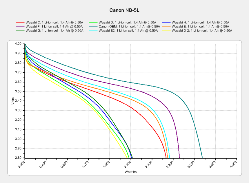
Canon NB-5L – 2017-08-05
I re-ran a couple of the batteries to make sure they hadn’t faded away from disuse, which didn’t materially change the results. The lightly used Canon OEM battery continues to lead the, ah, pack.
The camera’s lens capsule accumulated a fair bit of dust from many years in my pocket, which lowers its overall contrast and wrecks the high f/ images produced with the microscope adapter.
The Sandisk Extreme Pro 64 GB MicroSDXC (whew) card in the Sony HDR-AS30V had been working fine, but recently the camera crashed in mid-ride after spitting out an unreadable video file. I reformatting the card, which seemed to restore its good humor, and preemptively dropped $36 on a fancy Sandisk High Endurance Video Monitoring Card from a Nominally Reputable Amazon seller:
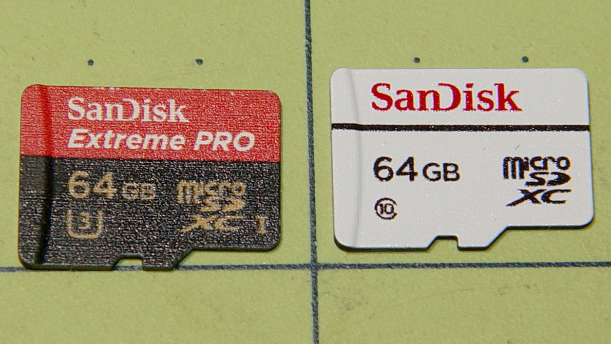
Sandisk – 64 GB MicroSDXC cards
The package & card production values seem high enough to make me think it’s genuine, despite the white-label thing SanDisk has goin’ on; it matches their website pix closely enough.
Popping it into a USB 3.0 adapter, plugging that into the new-to-me Dell Optiplex 9010’s front-panel USB 3.0 port, and unleashing f3probe produced encouraging results:
sudo f3probe -t /dev/sde
[sudo] password for ed:
F3 probe 6.0
Copyright (C) 2010 Digirati Internet LTDA.
This is free software; see the source for copying conditions.

WARNING: Probing normally takes from a few seconds to 15 minutes, but
         it can take longer. Please be patient.

Probe finished, recovering blocks... Done

Good news: The device `/dev/sde' is the real thing

Device geometry:
	         *Usable* size: 59.48 GB (124735488 blocks)
	        Announced size: 59.48 GB (124735488 blocks)
	                Module: 64.00 GB (2^36 Bytes)
	Approximate cache size: 0.00 Byte (0 blocks), need-reset=no
	   Physical block size: 512.00 Byte (2^9 Bytes)

Probe time: 4'26"
 Operation: total time / count = avg time
      Read: 2'42" / 4197135 = 38us
     Write: 1'41" / 4192321 = 24us
     Reset: 1.00s / 1 = 1.00s
Just for completeness, I unleashed f3write to fill it with pseudorandom data:
So it reads lickety-split, but writes much more slowly. Fortunately, the HDR-AS30 camera pops out a 4 GB file every 22.75 minute = 2.9 MB/s, so the card has a smidge of headroom while writing.
The specs claim “up to 10,000 hours” of Full HD recording. If so, I’m looking at a card good for “up to 40 years“ of riding at 1 hour/ride and 250 ride/year. For 36 bucks, how can ya go wrong?
I’ll take it for a few rides to see what happens …
The packaging includes a link to a Windows / Mac data recovery program, plus the serial number required to activate the download. I’ll continue to eke out a miserable existence with ordinary Linux disk / file maintenance tools, as I’m no longer enthused about “free” programs requiring secret handshakes for activation on a single computer with an OS I no longer use, particularly a program that auto-pumpkinates after a year:
Please fill in the data accurately as this information will be needed to reactivate the software if you ever need to move the software to a different computer.
Isolating the USB port from the laptop eliminated a nasty ground loop, turning off the OLED while making measurements stifled a huge noise source, and averaging a few ADC readings produced this pleasing plot:
Resonator 0 Spectrum
Those nice smooth curves suggest the tester isn’t just measuring random junk.
The OLED summarizes the results after the test sequence:
LF Crystal Tester – OLED test summary – Resonator 0
Collecting all the numbers for that resonator in one place:
I ripped that nice layout directly from my November Circuit Cellar column, because I’m absolutely not even going to try to recreate those equations here.
We watched a female Monarch Butterfly lay eggs on the stand of milkweed behind the house. She also found a lone plant in the vegetable garden that’s now standing in a vase on the kitchen table where we can keep an eye on the proceedings.
So far, so good:
Monarch Butterfly Egg on Milkweed Leaf – 2017-07-29
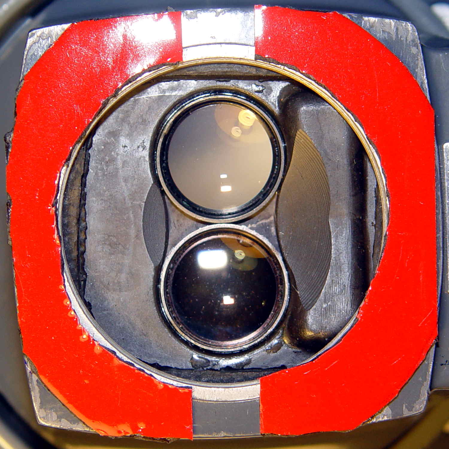
The tiny lip holding the new LED ring light into the microscope snout lacked enough traction and deposited the ring light on the desk. Having picked up a roll of Scotch Extreme Mounting Tape to see how well it works to attach LEDs to vacuum tubes, I’ll see how well it affixes a ring light to a microscope:
Stereo zoom microscope – taped snout
The red plastic film separates the tape layers on the spool; the tape itself consists of incredibly sticky, gooey adhesive on a very flexible foam backing. As you can tell from the ragged edges, cutting it requires some effort, with the adhesive instantly gumming up scissors. I applied a razor knife around the microscope snout’s perimeter, pressing from the red film side and pulling the cut sections apart as I went.
The adhesive exposed on the edges of the roll will glue it to anything it touches, so hang up the roll. Laying it on a shelf will definitely cause heartache & confusion.
The instructions on the back label suggest 2 square inches of tape will hold 1 pound:
Scotch Extreme Mounting Tape – label
Given that the ring light weighs a few ounces, tops, those two strips should do fine.