With the joystick button and LM75 temperature sensor running, this chunk of code lets you nudge the nominal DDS oscillator frequency by 1 Hz every 100 ms:
| // Zero-beat oscillator to 10 MHz GPS-locked reference | |
| printf("Zero beat DDS oscillator against GPS\n"); | |
| TempFreq.fx_64 = CALFREQ; | |
| u8x8.clearDisplay(); | |
| byte ln = 0; | |
| u8x8.drawString(0,ln++,"10 MHz Zero Beat"); | |
| u8x8.drawString(0,ln++,"<- Joystick ->"); | |
| u8x8.drawString(0,ln++," Button = set "); | |
| int32_t OldOffset = OscOffset; | |
| while (analogRead(PIN_JOYBUTTTON) > 500) { | |
| int ai = analogRead(PIN_JOY_Y) – 512; // totally ad-hoc axes | |
| if (ai < -100) { | |
| OscOffset += 1; | |
| } | |
| else if (ai > 100) { | |
| OscOffset -= 1; | |
| } | |
| if (OscOffset != OldOffset) { | |
| ln = 4; | |
| sprintf(Buffer,"Offset %8ld",OscOffset); | |
| u8x8.drawString(0,ln++,Buffer); | |
| CalcOscillator(OscOffset); // recalculate constants | |
| TempCount.fx_64 = MultiplyFixedPt(TempFreq,CtPerHz); // recalculate delta phase count | |
| WriteDDS(TempCount.fx_32.high); // should be 10 MHz out! | |
| OldOffset = OscOffset; | |
| } | |
| Wire.requestFrom(LM75_ADDR,2); | |
| Temperature.fx_32.high = Wire.read(); | |
| Temperature.fx_32.low = (uint32_t)Wire.read() << 24; | |
| PrintFixedPtRounded(Buffer,Temperature,3); | |
| ln = 7; | |
| u8x8.drawString(0,ln,"DDS Temp"); | |
| u8x8.drawString(16-strlen(Buffer),ln++,Buffer); | |
| delay(100); | |
| } | |
| printf("Oscillator offset: %ld\n",OscOffset); |
While that’s happening, you compare the DDS output to a reference frequency on an oscilloscope:

The top trace (and scope trigger) is the GPS-locked 10 MHz reference, the lower trace is the AD9850 DDS output (not through the MAX4165 buffer amp, because bandwidth). If the frequencies aren’t identical, the DDS trace will crawl left or right with respect to the reference: leftward if the DDS frequency is too high, rightward if it’s too low. If the DDS frequency is way off, then the waveform may scamper or run, with the distinct possibility of aliasing on digital scopes; you have been warned.
The joystick acts as a bidirectional switch, rather than an analog input, with the loop determining the step increment and timing. The ad-hoc axis orientation lets you (well, me) push the joystick against the waveform crawl, which gradually slows down and stops when the offset value makes the DDS output match the reference.
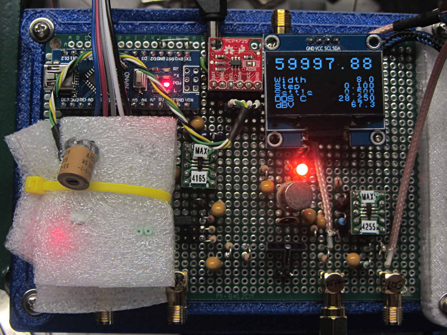
The OLED displays the current status:

The lurid red glow along the bottom is lens flare from the amber LED showing the relay is turned on. The slightly dimmer characters across the middle of the display show how the refresh interacts with the camera shutter at 1/30 s exposure.
N.B.: Normally, you know the DDS clock oscillator frequency with some accuracy. Dividing that value into 232 (for the AD9850) gives you the delta-phase count / frequency ratio that converts a desired DDS output frequency into the delta-phase value telling the DDS to make it happen.
In this case, I want the output frequency to be exactly 10.000000 MHz, so I’m adjusting the oscillator frequency (nominal 125 MHz + offset), calculating the corresponding count-to-Hz ratio, multiplying the ratio by 10.000000 MHz, stuffing the ensuing count into the DDS, and eyeballing what happens. When the oscillator frequency variable matches the actual oscillator frequency, then the actual output will 10.000000 MHz and the ratio will be correct.
Got it? Took me a while.
Although the intent is to tune for best frequency match and move on, you (well, I) can use this to accumulate a table of frequency offset vs. temperature pairs, from which a (presumably simple) formula can be conjured to render this step unnecessary.
The Arduino source code as a GitHub Gist:
| // 60 kHz crystal tester | |
| // Ed Nisley – KE4ZNU | |
| #include <avr/pgmspace.h> | |
| #include <U8g2lib.h> | |
| #include <U8x8lib.h> | |
| #include <Adafruit_MCP4725.h> | |
| //——————— | |
| // Pin locations | |
| #define PIN_SYNC 5 | |
| #define PIN_CX_SHORT 6 | |
| #define PIN_DDS_RESET 7 | |
| #define PIN_DDS_LATCH 8 | |
| #define PIN_HEARTBEAT 9 | |
| #define PIN_LOG_AMP A0 | |
| #define PIN_JOYBUTTTON A1 | |
| #define PIN_JOY_Y A2 | |
| #define PIN_JOY_X A3 | |
| // SPI & I2C use hardware support: these pins are predetermined | |
| #define PIN_SS 10 | |
| #define PIN_MOSI 11 | |
| #define PIN_MISO 12 | |
| #define PIN_SCK 13 | |
| #define PIN_IIC_SDA A4 | |
| #define PIN_IIC_SCL A5 | |
| // IIC Hardware addresses | |
| // OLED library uses its default address | |
| #define LM75_ADDR 0x48 | |
| #define SH1106_ADDR 0x70 | |
| #define MCP4725_ADDR 0x60 | |
| // Useful constants | |
| #define GIGA 1000000000LL | |
| #define MEGA 1000000LL | |
| #define KILO 1000LL | |
| #define ONE_FX (1LL << 32) | |
| #define CALFREQ (10LL * MEGA * ONE_FX) | |
| // Structures for 64-bit fixed point numbers | |
| // Low word = fractional part | |
| // High word = integer part | |
| struct ll_fx { | |
| uint32_t low; // fractional part | |
| uint32_t high; // integer part | |
| }; | |
| union ll_u { | |
| uint64_t fx_64; | |
| struct ll_fx fx_32; | |
| }; | |
| // Define semi-constant values | |
| union ll_u CenterFreq = {(60000 – 4) * ONE_FX}; // center of scan | |
| //union ll_u CenterFreq = {(32768 – 2) * ONE_FX}; // center of scan | |
| #define NOMINAL_OSC ((125 * MEGA) * ONE_FX) | |
| union ll_u Oscillator = {NOMINAL_OSC}; // oscillator frequency | |
| int32_t OscOffset = -414; // measured offset from NOMINAL_OSC | |
| uint16_t ScanWidth = 4*2; // width must be an even integer | |
| uint16_t ScanSettleMS = 2000; // milliseconds of settling time per measurement | |
| union ll_u ScanStepSize = {ONE_FX / 10}; // 0.1 Hz is smallest practical decimal step | |
| //union ll_u ScanStepSize = {ONE_FX / 34}; // 0.0291 is smallest possible step | |
| // Global variables of interest to everyone | |
| union ll_u ScanFrom, ScanTo; // may be larger than unsigned ints | |
| union ll_u ScanFreq; // fixed-point frequency scan settings | |
| union ll_u PeakFreq; // records maximum response point | |
| union ll_u PeakdB; // and corresponding log amp output | |
| union ll_u SeriesPeakLow,SeriesPeakHigh; // peak with CX short and CX in circuit | |
| union ll_u CtPerHz; // will be 2^32 / oscillator | |
| union ll_u HzPerCt; // will be oscillator / 2^32 | |
| char Buffer[10+1+10+1]; // string buffer for fixed point number conversions | |
| union ll_u Temperature; // read from LM75A | |
| // Hardware library variables | |
| U8X8_SH1106_128X64_NONAME_HW_I2C u8x8(U8X8_PIN_NONE); | |
| //U8X8_SH1106_128X64_NONAME_4W_HW_SPI u8x8(PIN_DISP_SEL, PIN_DISP_DC , PIN_DISP_RST); | |
| //U8X8_SH1106_128X64_NONAME_4W_SW_SPI u8x8(PIN_SCK, PIN_MOSI, PIN_DISP_SEL, PIN_DISP_DC , PIN_DISP_RST); | |
| #define DAC_WR false | |
| #define DAC_WR_EEP true | |
| #define DAC_BITS 12 | |
| #define DAC_MAX 0x0fff | |
| Adafruit_MCP4725 XAxisDAC; // I²C DAC for X axis output | |
| uint32_t XAxisValue; // DAC parameter uses 32 bits | |
| union ll_u LogAmpdB; // computed dB value | |
| #define HEARTBEAT_MS 3000 | |
| unsigned long MillisNow,MillisThen; | |
| //———– | |
| // Useful functions | |
| // Pin twiddling | |
| void TogglePin(char bitpin) { | |
| digitalWrite(bitpin,!digitalRead(bitpin)); // toggle the bit based on previous output | |
| } | |
| void PulsePin(char bitpin) { | |
| TogglePin(bitpin); | |
| TogglePin(bitpin); | |
| } | |
| void WaitButtonDown() { | |
| word ai; | |
| do { | |
| ai = analogRead(PIN_JOYBUTTTON); | |
| } while (ai > 500); | |
| } | |
| void WaitButtonUp() { | |
| word ai; | |
| do { | |
| ai = analogRead(PIN_JOYBUTTTON); | |
| } while (ai < 500); | |
| } | |
| // Hardware-assisted SPI I/O | |
| void EnableSPI(void) { | |
| digitalWrite(PIN_SS,HIGH); // set SPI into Master mode | |
| SPCR |= 1 << SPE; | |
| } | |
| void DisableSPI(void) { | |
| SPCR &= ~(1 << SPE); | |
| } | |
| void WaitSPIF(void) { | |
| while (! (SPSR & (1 << SPIF))) { | |
| // TogglePin(PIN_HEARTBEAT); | |
| // TogglePin(PIN_HEARTBEAT); | |
| continue; | |
| } | |
| } | |
| byte SendRecSPI(byte Dbyte) { // send one byte, get another in exchange | |
| SPDR = Dbyte; | |
| WaitSPIF(); | |
| return SPDR; // SPIF will be cleared | |
| } | |
| //————– | |
| // DDS module | |
| void EnableDDS(void) { | |
| digitalWrite(PIN_DDS_LATCH,LOW); // ensure proper startup | |
| digitalWrite(PIN_DDS_RESET,HIGH); // minimum reset pulse 40 ns, not a problem | |
| digitalWrite(PIN_DDS_RESET,LOW); | |
| delayMicroseconds(1); // max latency 100 ns, not a problem | |
| DisableSPI(); // allow manual control of outputs | |
| digitalWrite(PIN_SCK,LOW); // ensure clean SCK pulse | |
| PulsePin(PIN_SCK); // … to latch hardwired config bits | |
| PulsePin(PIN_DDS_LATCH); // load hardwired config bits = begin serial mode | |
| EnableSPI(); // turn on hardware SPI controls | |
| SendRecSPI(0x00); // shift in serial config bits | |
| PulsePin(PIN_DDS_LATCH); // load serial config bits | |
| } | |
| // Write delta phase count to DDS | |
| // This comes from the integer part of a 64-bit scaled value | |
| void WriteDDS(uint32_t DeltaPhase) { | |
| SendRecSPI((byte)DeltaPhase); // low-order byte first | |
| SendRecSPI((byte)(DeltaPhase >> 8)); | |
| SendRecSPI((byte)(DeltaPhase >> 16)); | |
| SendRecSPI((byte)(DeltaPhase >> 24)); | |
| SendRecSPI(0x00); // 5 MSBs = phase = 0, 3 LSBs must be zero | |
| PulsePin(PIN_DDS_LATCH); // write data to DDS | |
| } | |
| //————– | |
| // Log amp module | |
| #define LOG_AMP_SAMPLES 10 | |
| #define LOG_AMP_DELAYMS 10 | |
| uint64_t ReadLogAmp() { | |
| union ll_u LogAmpRaw; | |
| LogAmpRaw.fx_64 = 0; | |
| for (byte i=0; i<LOG_AMP_SAMPLES; i++) { | |
| LogAmpRaw.fx_32.high += analogRead(PIN_LOG_AMP); | |
| delay(LOG_AMP_DELAYMS); | |
| } | |
| LogAmpRaw.fx_64 /= LOG_AMP_SAMPLES; // figure average from totally ad-hoc number of samples | |
| LogAmpRaw.fx_64 *= 5; // convert from ADC counts to voltage | |
| LogAmpRaw.fx_64 /= 1024; | |
| LogAmpRaw.fx_64 /= 24; // convert from voltage to dBV at 24 mV/dBV | |
| LogAmpRaw.fx_64 *= 1000; | |
| return LogAmpRaw.fx_64; | |
| } | |
| //———– | |
| // Scan DDS and record response | |
| void ScanCrystal() { | |
| byte ln; | |
| union ll_u Temp, TestFreq, TestCount; | |
| XAxisValue = 0; | |
| PeakdB.fx_64 = 0; | |
| printf("CX: %s\n",digitalRead(PIN_CX_SHORT) ? "short" : "enable"); | |
| for (ScanFreq = ScanFrom; | |
| ScanFreq.fx_64 < (ScanTo.fx_64 + ScanStepSize.fx_64 / 2); | |
| ScanFreq.fx_64 += ScanStepSize.fx_64) { | |
| digitalWrite(PIN_SYNC,HIGH); | |
| TestCount.fx_64 = MultiplyFixedPt(ScanFreq,CtPerHz); // compute DDS delta phase | |
| TestCount.fx_32.low = 0; // truncate count to integer | |
| TestFreq.fx_64 = MultiplyFixedPt(TestCount,HzPerCt); // compute actual frequency | |
| Temp.fx_64 = (DAC_MAX * (ScanFreq.fx_64 – ScanFrom.fx_64)); // figure X as fraction | |
| Temp.fx_64 /= ScanWidth; | |
| XAxisValue = Temp.fx_32.high; | |
| digitalWrite(PIN_HEARTBEAT,HIGH); | |
| WriteDDS(TestCount.fx_32.high); // set DDS to new frequency | |
| XAxisDAC.setVoltage(XAxisValue,DAC_WR); // and set X axis to match | |
| digitalWrite(PIN_SYNC,LOW); | |
| if (ScanFreq.fx_64 == ScanFrom.fx_64) { | |
| delay(3*ScanSettleMS); // very long settling time | |
| } | |
| else { | |
| delay(ScanSettleMS); // small steps are faster | |
| } | |
| LogAmpdB.fx_64 = ReadLogAmp(); // fetch avg value | |
| if (LogAmpdB.fx_64 > PeakdB.fx_64) { // hit a new high? | |
| PeakFreq = TestFreq; // save actual frequency | |
| PeakdB = LogAmpdB; | |
| ln = digitalRead(PIN_CX_SHORT) ? 4 : 5; // CX selects row | |
| PrintFixedPtRounded(Buffer,TestFreq,2); // display actual peak | |
| u8x8.drawString(0,ln,Buffer); | |
| PrintFixedPtRounded(Buffer,LogAmpdB,1); // tack on response | |
| u8x8.drawString(16-strlen(Buffer),ln,Buffer); | |
| } | |
| ln = 0; | |
| PrintFixedPtRounded(Buffer,TestFreq,2); // display current frequency | |
| u8x8.draw2x2String(0,ln++,Buffer); | |
| ln++; // double-high characters | |
| printf("%9s ",Buffer); // log to serial port | |
| PrintFixedPtRounded(Buffer,LogAmpdB,1); // display response | |
| u8x8.drawString(0,ln,"dBV "); | |
| u8x8.drawString(16-strlen(Buffer),ln++,Buffer); | |
| printf(", %6s\n",Buffer); // and log it | |
| } | |
| } | |
| //———– | |
| // Round scaled fixed point to specific number of decimal places: 0 through 8 | |
| // You should display the value with only Decimals characters beyond the point | |
| // Must calculate rounding value as separate variable to avoid mystery error | |
| uint64_t RoundFixedPt(union ll_u TheNumber,unsigned Decimals) { | |
| union ll_u Rnd; | |
| Rnd.fx_64 = (ONE_FX >> 1) / (pow(10LL,Decimals)); // that's 0.5 / number of places | |
| TheNumber.fx_64 = TheNumber.fx_64 + Rnd.fx_64; | |
| return TheNumber.fx_64; | |
| } | |
| //———– | |
| // Multiply two unsigned scaled fixed point numbers without overflowing a 64 bit value | |
| // Perforce, the product of the two integer parts mut be < 2^32 | |
| uint64_t MultiplyFixedPt(union ll_u Mcand, union ll_u Mplier) { | |
| union ll_u Result; | |
| Result.fx_64 = ((uint64_t)Mcand.fx_32.high * (uint64_t)Mplier.fx_32.high) << 32; // integer parts (clear fract) | |
| Result.fx_64 += ((uint64_t)Mcand.fx_32.low * (uint64_t)Mplier.fx_32.low) >> 32; // fraction parts (always < 1) | |
| Result.fx_64 += (uint64_t)Mcand.fx_32.high * (uint64_t)Mplier.fx_32.low; // cross products | |
| Result.fx_64 += (uint64_t)Mcand.fx_32.low * (uint64_t)Mplier.fx_32.high; | |
| return Result.fx_64; | |
| } | |
| //———– | |
| // Long long print-to-buffer helpers | |
| // Assumes little-Endian layout | |
| void PrintHexLL(char *pBuffer,union ll_u FixedPt) { | |
| sprintf(pBuffer,"%08lx %08lx",FixedPt.fx_32.high,FixedPt.fx_32.low); | |
| } | |
| // converts all 9 decimal digits of fraction, which should suffice | |
| void PrintFractionLL(char *pBuffer,union ll_u FixedPt) { | |
| union ll_u Fraction; | |
| Fraction.fx_64 = FixedPt.fx_32.low; // copy 32 fraction bits, high order = 0 | |
| Fraction.fx_64 *= GIGA; // times 10^9 for conversion | |
| Fraction.fx_64 >>= 32; // align integer part in low long | |
| sprintf(pBuffer,"%09lu",Fraction.fx_32.low); // convert low long to decimal | |
| } | |
| void PrintIntegerLL(char *pBuffer,union ll_u FixedPt) { | |
| sprintf(pBuffer,"%lu",FixedPt.fx_32.high); | |
| } | |
| void PrintFixedPt(char *pBuffer,union ll_u FixedPt) { | |
| PrintIntegerLL(pBuffer,FixedPt); // do the integer part | |
| pBuffer += strlen(pBuffer); // aim pointer beyond integer | |
| *pBuffer++ = '.'; // drop in the decimal point, tick pointer | |
| PrintFractionLL(pBuffer,FixedPt); | |
| } | |
| void PrintFixedPtRounded(char *pBuffer,union ll_u FixedPt,unsigned Decimals) { | |
| char *pDecPt; | |
| FixedPt.fx_64 = RoundFixedPt(FixedPt,Decimals); | |
| PrintIntegerLL(pBuffer,FixedPt); // do the integer part | |
| pBuffer += strlen(pBuffer); // aim pointer beyond integer | |
| pDecPt = pBuffer; // save the point location | |
| *pBuffer++ = '.'; // drop in the decimal point, tick pointer | |
| PrintFractionLL(pBuffer,FixedPt); // do the fraction | |
| if (Decimals == 0) | |
| *pDecPt = 0; // 0 places means discard the decimal point | |
| else | |
| *(pDecPt + Decimals + 1) = 0; // truncate string to leave . and Decimals chars | |
| } | |
| //———– | |
| // Calculate useful "constants" from oscillator info | |
| // Offset is integer Hz, because 0.1 ppm = 1 Hz at 10 MHz is as close as we can measure | |
| void CalcOscillator(int32_t Offset) { | |
| Oscillator.fx_64 = NOMINAL_OSC + ((int64_t)Offset << 32); | |
| HzPerCt.fx_32.low = Oscillator.fx_32.high; // divide oscillator by 2^32 with simple shifting | |
| HzPerCt.fx_32.high = 0; | |
| CtPerHz.fx_64 = -1; // Compute (2^32 – 1) / oscillator | |
| CtPerHz.fx_64 /= (uint64_t)Oscillator.fx_32.high; // remove 2^32 scale factor from divisor | |
| } | |
| //– Helper routine for printf() | |
| int s_putc(char c, FILE *t) { | |
| Serial.write(c); | |
| } | |
| //———– | |
| void setup () { | |
| union ll_u TempFreq,TempCount; | |
| pinMode(PIN_HEARTBEAT,OUTPUT); | |
| digitalWrite(PIN_HEARTBEAT,LOW); // show we got here | |
| pinMode(PIN_SYNC,OUTPUT); | |
| digitalWrite(PIN_SYNC,LOW); | |
| Serial.begin (115200); | |
| fdevopen(&s_putc,0); // set up serial output for printf() | |
| Serial.println (F("60 kHz Crystal Tester")); | |
| Serial.println (F("Ed Nisley – KE4ZNU – June 2017\n")); | |
| // DDS module controls | |
| pinMode(PIN_DDS_LATCH,OUTPUT); | |
| digitalWrite(PIN_DDS_LATCH,LOW); | |
| pinMode(PIN_DDS_RESET,OUTPUT); | |
| digitalWrite(PIN_DDS_RESET,HIGH); | |
| // Light up the display | |
| Serial.println("Initialize OLED"); | |
| u8x8.begin(); | |
| u8x8.setFont(u8x8_font_artossans8_r); | |
| // u8x8.setPowerSave(0); | |
| u8x8.setFont(u8x8_font_pxplusibmcga_f); | |
| u8x8.draw2x2String(0,0,"XtalTest"); | |
| u8x8.drawString(0,3,"Ed Nisley"); | |
| u8x8.drawString(0,4," KE4ZNU"); | |
| u8x8.drawString(0,6,"June 2017"); | |
| // configure SPI hardware | |
| pinMode(PIN_SS,OUTPUT); // set up manual controls | |
| digitalWrite(PIN_SS,HIGH); | |
| pinMode(PIN_SCK,OUTPUT); | |
| digitalWrite(PIN_SCK,LOW); | |
| pinMode(PIN_MOSI,OUTPUT); | |
| digitalWrite(PIN_MOSI,LOW); | |
| pinMode(PIN_MISO,INPUT_PULLUP); | |
| SPCR = B00110000; // Auto SPI: no int, disabled, LSB first, master, + edge, leading, f/4 | |
| SPSR = B00000000; // not double data rate | |
| TogglePin(PIN_HEARTBEAT); // show we got here | |
| // Set up X axis DAC output | |
| XAxisDAC.begin(MCP4725_ADDR); // start up MCP4725 DAC at Sparkfun address | |
| // XAxisDAC.setVoltage(0,DAC_WR_EEP); // do this once per DAC to set power-on at 0 V | |
| XAxisDAC.setVoltage(0,DAC_WR); // force 0 V after a reset without a power cycle | |
| // LM75A temperature sensor requires no setup! | |
| // External capacitor in test fixture | |
| pinMode(PIN_CX_SHORT,OUTPUT); | |
| digitalWrite(PIN_CX_SHORT,HIGH); // short = remove external cap | |
| // Scan limits and suchlike | |
| ScanFrom.fx_64 = CenterFreq.fx_64 – (ONE_FX * ScanWidth/2); | |
| ScanTo.fx_64 = CenterFreq.fx_64 + (ONE_FX * ScanWidth/2); | |
| PrintFixedPtRounded(Buffer,CenterFreq,1); | |
| printf("Center freq: %s Hz\n",Buffer); | |
| printf("Settling time: %d ms\n",ScanSettleMS); | |
| // Wake up and load the DDS | |
| CalcOscillator(OscOffset); // use default oscillator frequency | |
| Serial.print("\nStarting DDS: "); | |
| TempFreq.fx_64 = CALFREQ; | |
| TempCount.fx_64 = MultiplyFixedPt(TempFreq,CtPerHz); | |
| // PrintHexLL(Buffer,TempCount); | |
| // printf(" Count: %s ",Buffer); | |
| EnableDDS(); | |
| WriteDDS(TempCount.fx_32.high); | |
| Serial.println("running\n"); | |
| // Zero-beat oscillator to 10 MHz GPS-locked reference | |
| printf("Zero beat DDS oscillator against GPS\n"); | |
| TempFreq.fx_64 = CALFREQ; | |
| u8x8.clearDisplay(); | |
| byte ln = 0; | |
| u8x8.drawString(0,ln++,"10 MHz Zero Beat"); | |
| u8x8.drawString(0,ln++,"<- Joystick ->"); | |
| u8x8.drawString(0,ln++," Button = set "); | |
| int32_t OldOffset = OscOffset; | |
| while (analogRead(PIN_JOYBUTTTON) > 500) { | |
| int ai = analogRead(PIN_JOY_Y) – 512; // totally ad-hoc axes | |
| if (ai < -100) { | |
| OscOffset += 1; | |
| } | |
| else if (ai > 100) { | |
| OscOffset -= 1; | |
| } | |
| if (OscOffset != OldOffset) { | |
| ln = 4; | |
| sprintf(Buffer,"Offset %8ld",OscOffset); | |
| u8x8.drawString(0,ln++,Buffer); | |
| CalcOscillator(OscOffset); // recalculate constants | |
| TempCount.fx_64 = MultiplyFixedPt(TempFreq,CtPerHz); // recalculate delta phase count | |
| WriteDDS(TempCount.fx_32.high); // should be 10 MHz out! | |
| OldOffset = OscOffset; | |
| } | |
| Wire.requestFrom(LM75_ADDR,2); | |
| Temperature.fx_32.high = Wire.read(); | |
| Temperature.fx_32.low = (uint32_t)Wire.read() << 24; | |
| PrintFixedPtRounded(Buffer,Temperature,3); | |
| ln = 7; | |
| u8x8.drawString(0,ln,"DDS Temp"); | |
| u8x8.drawString(16-strlen(Buffer),ln++,Buffer); | |
| delay(100); | |
| } | |
| printf("Oscillator offset: %ld\n",OscOffset); | |
| u8x8.clearDisplay(); | |
| Serial.println("\nStartup done\n"); | |
| MillisThen = millis(); | |
| } | |
| //———– | |
| void loop () { | |
| byte ln; | |
| union ll_u Temp; | |
| u8x8.setPowerSave(0); | |
| u8x8.clearDisplay(); | |
| ln = 0; | |
| u8x8.draw2x2String(0,2*ln++,"Press"); | |
| u8x8.draw2x2String(0,2*ln++,"Button"); | |
| u8x8.draw2x2String(0,2*ln++,"To Start"); | |
| u8x8.draw2x2String(0,2*ln++,"Test"); | |
| printf("Waiting for button press: "); | |
| WaitButtonDown(); | |
| printf("\n"); | |
| u8x8.clearDisplay(); | |
| // u8x8.setPowerSave(1); | |
| // Report temperature | |
| Wire.requestFrom(LM75_ADDR,2); | |
| Temperature.fx_32.high = Wire.read(); | |
| Temperature.fx_32.low = (uint32_t)Wire.read() << 24; | |
| PrintFixedPtRounded(Buffer,Temperature,3); | |
| printf("Oscillator temperature: %s C\n",Buffer); | |
| ln = 3; | |
| u8x8.drawString(0,ln,"DDS Temp"); | |
| u8x8.drawString(16-strlen(Buffer),ln,Buffer); | |
| // First scan: CX shorted | |
| digitalWrite(PIN_CX_SHORT,HIGH); | |
| delay(10); | |
| ScanCrystal(); | |
| SeriesPeakLow = PeakFreq; | |
| PrintFixedPtRounded(Buffer,PeakFreq,2); // report peak freq | |
| printf("\nPeak: %s Hz",Buffer); | |
| PrintFixedPtRounded(Buffer,PeakdB,1); // tack on response | |
| printf(" %s dbV\n",Buffer); | |
| // Second scan: CX in circuit | |
| digitalWrite(PIN_CX_SHORT,LOW); | |
| delay(10); | |
| ScanFrom.fx_64 = SeriesPeakLow.fx_64 – (2 * ONE_FX); // tighten scan limits | |
| ScanFrom.fx_32.low = 0; | |
| ScanTo.fx_64 = SeriesPeakLow.fx_64 + (4 * ONE_FX); | |
| ScanTo.fx_32.low = 0; | |
| ScanCrystal(); | |
| SeriesPeakHigh = PeakFreq; | |
| PrintFixedPtRounded(Buffer,PeakFreq,2); // report peak freq | |
| printf("\nPeak: %s Hz",Buffer); | |
| PrintFixedPtRounded(Buffer,PeakdB,1); // tack on response | |
| printf(" %s dbV\n",Buffer); | |
| ln = 0; | |
| u8x8.draw2x2String(0,ln," -Done- "); | |
| ln +=2; | |
| u8x8.clearLine(ln); | |
| ln = 6; | |
| Temp.fx_64 = SeriesPeakHigh.fx_64 – SeriesPeakLow.fx_64; | |
| PrintFixedPtRounded(Buffer,Temp,2); | |
| printf("Delta frequency: %s\n",Buffer); | |
| u8x8.drawString(0,ln,"Delta freq"); | |
| u8x8.drawString(16-strlen(Buffer),ln,Buffer); | |
| ln = 7; | |
| u8x8.drawString(0,ln,"Press button …"); | |
| u8x8.setPowerSave(0); | |
| WaitButtonDown(); | |
| WaitButtonUp(); | |
| } | |