Ed Nisley's Blog: Shop notes, electronics, firmware, machinery, 3D printing, laser cuttery, and curiosities. Contents: 100% human thinking, 0% AI slop.
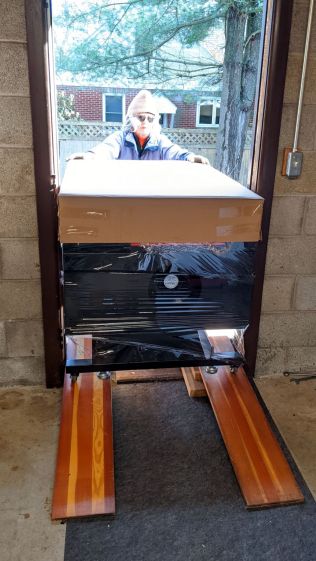
Lacking a loading dock, I built a level unloading platform in the driveway:
OMTech 60W Laser Cutter – unloading platform
The OMTech 60 W laser cutter arrived inside a generous supply of plywood obviously intended for practice cutting and engraving:
OMTech 60W Laser Cutter – crate
Knowing the crate wouldn’t fit through our “36 inch” basement door, we stripped the cutter down to the crate’s steel-framed baseplate:
OMTech 60W Laser Cutter – uncrated
I raised the cutter (using the foot-pad screws) enough to slide 3/4 inch planks under the casters so we could roll it over the lip of the crate base.
The specs say it’s 34 inches wide, but, not at all to our surprise, that’s just the cabinet. The hinges on the access hatches and the lid handle make it just over 35 inches wide, which we slowly and carefully verified would not fit through the 34 inch door opening:
OMTech 60W Laser Cutter – slow fit check
Raising the lid to get the handle out of the way, then pushing gently inward on the sides, eased it through without damage to either the cabinet or the door frame:
OMTech 60W Laser Cutter – door fit
Standing on the plank let me raise the outer end enough to roll it forward and lower the casters onto the planks inside the door.
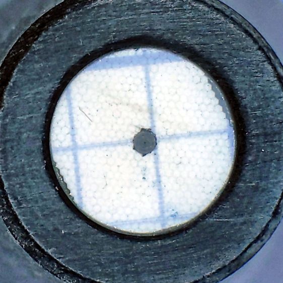
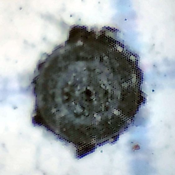
The supplied aquarium pump circulates five gallons of distilled water to cool the laser tube. My simple test patterns so far haven’t dumped much heat into the water:
Dot Mode – 15 pct power – 1 2 3 ms on – 0.25 mm spacing
The doily on the left shows 9% power cuts right through paper. Dot Mode fires the laser every 0.25 mm (in this case) for a specified number of milliseconds to reduce the total energy; 3 ms produces dark dots, 1 ms is a pale brown, and 2 ms looks pretty good.
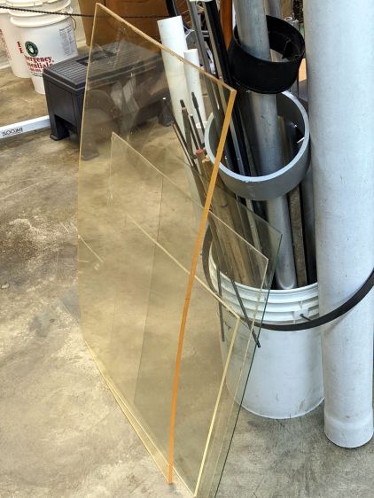
Concerted rummaging in the Basement Warehouse produced some rather old acrylic sheets:
Acrylic Stockpile
Washing with detergent and denatured alcohol cleaned off a lot of grunge, but the yellow tint says it’s been around for a while. In fact, It Came With The House™ when we bought it three decades ago.
One sheet was a status board in an automobile machine shop:
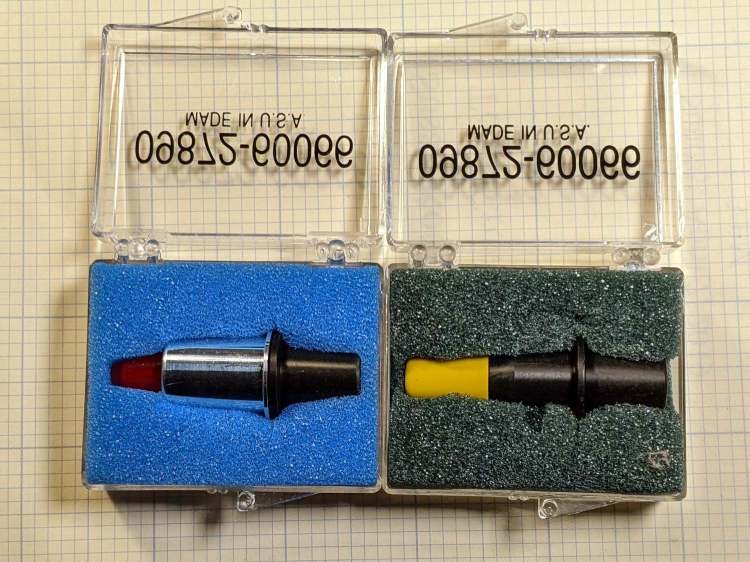
The metal-shell version is advertised as “09872-60066 Calibration Pen for fit HP DesignJet 2000CP 2500CP 2800CP 3000CP 3500CP 3800CP Original New” which makes absolutely no sense, as those were inkjet and laser printers with (AFAICT) no need for a “calibration pen”. Because nobody with those printers will buy (or even look for) a widget they can’t use, the price is surprisingly low, compared to the real ones occasionally found on eBay.
My guess: somebody halfway around the planet found a pile of Genuine HP plastic snap boxes, filled them with knockoff sights vaguely similar to the original (perhaps intended for a different plotter?), and marketed them with the usual (lack of) attention to veracity.
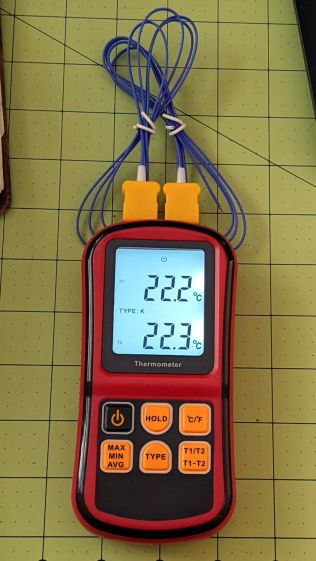
It seems suitable for a semi-permanent laser cooling water monitor, particularly because it can perform arithmetic to show the difference between the inlet and outlet temperatures. The minuscule clock face at the center top of the display shows it’s in auto-power-off mode, which can be defeated by a Vulcan Nerve Pinch while turning it on.
Having a large backlit display was a selling (well, buying) point and the instructions have this to say about its operation:
Dual Thermocouple meter – backlight instructions
The instructions say nothing about defeating the backlight timeout. The description is technically correct, because the two seconds before it goes dark is “within 30 seconds”, but I’d rather have a nicely lit display that’s on all the time.
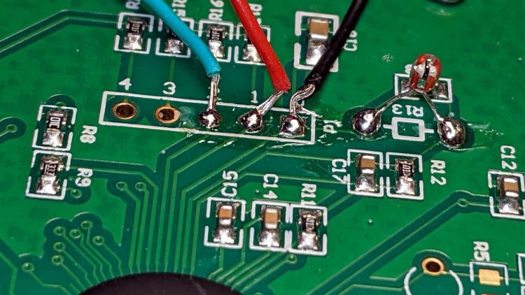
Five screws hold the back cover in place, with no nasty prying required to pull it apart, and the build quality is about what you’d expect for a cheap meter. The circuitry fits on a single PCB and perhaps the thermistor over on the right serves as the cold junction compensation:
Doodling the backlight circuit layout suggests it’s pretty simple, even without filling in the component values:
I replaced the transistor base resistor with a somewhat larger 4.7 kΩ SMD part and added a flying wire to jam the transistor on all the time:
The IC is a serial EEPROM with its VCC and ground pins in the usual places, so, when the power to the EEPROM goes on, the backlight turns on and stays on.
The meter draws a bit over 8 mA with the backlight running, which means the trio of AAA cells won’t last all that long. When things settle down, I’ll conjure a simpleminded power supply running from a convenient voltage inside the laser cabinet.
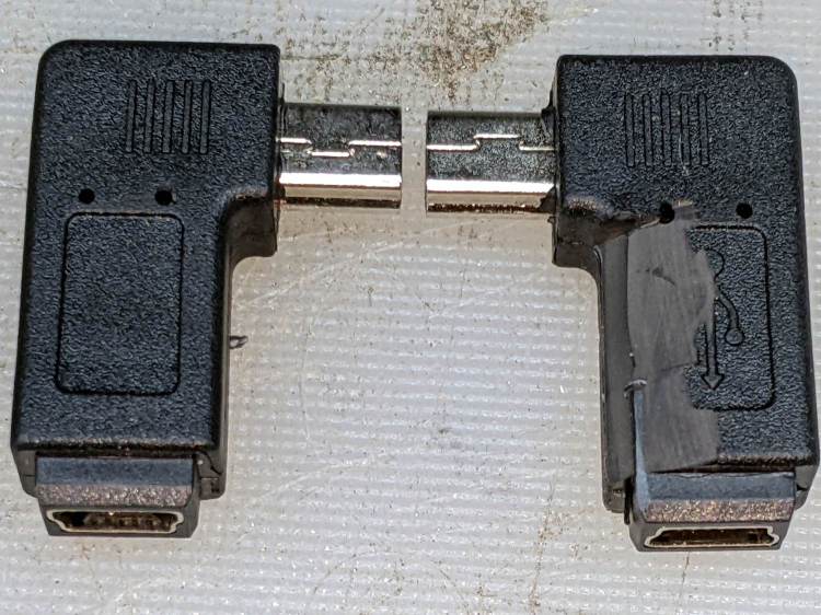
The Huion tablet on my desk has its USB cable sticking straight out of the left side, whereupon it must loop around to burrow under the shelf under my monitor on its way to the port on the back of the PC case. The loop snagged on all the clutter atop the desk and I finally got around to Fixing That Problem:
Which is a “left angle” adapter and which is a “right angle” adapter depends on which supplier you ask and how much you trust their descriptions / product photos, so you should get a set containing both: it’s the only way to be sure.
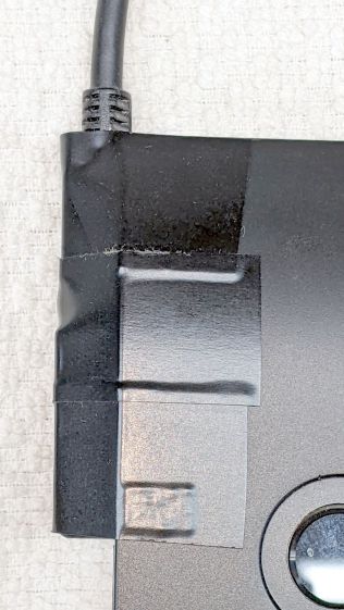
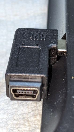
The one on the right (a “right angle”) shows a bit of carving, which came after the completely unsurprising discovery that the stylin’ curves on the side of the tablet collided with the rectangular adapter:
Huion tablet – misfit adapter
Some diligent X-Acto knife work carved away enough of both the adapter and the tablet case to snugly join them:
Huion tablet – plastic surgery
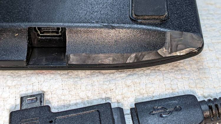
The hackery over on the far right fits around the USB cable’s molded connector. I simply cut away any parts that touched until the adapter seated firmly in the USB socket and the cable exited parallel to the edge.
Part of this involved not carving deeply enough into the adapter or cable connector to expose the internal wiring. I assumed the tablet didn’t have anything vital immediately inside that fancy curve, so that’s where I dug deepest.
Stick adapter + cable to the tablet with good-quality electrical tape and now the cable points directly to where it should go.