The Smell of Molten Projects in the Morning

Ed Nisley's Blog: Shop notes, electronics, firmware, machinery, 3D printing, laser cuttery, and curiosities. Contents: 100% human thinking, 0% AI slop.

Author: Ed

  • Duct Fan: Pipe Flow Test

    Duct Fan: Pipe Flow Test

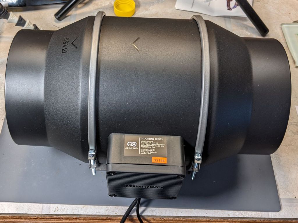
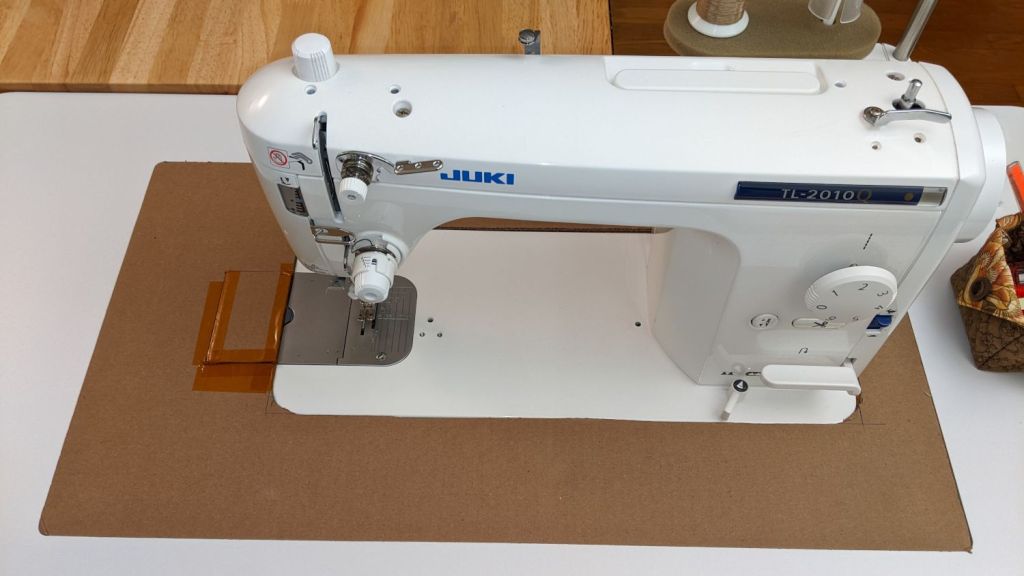
    A crude test setup to measure the duct fan’s air flow against resistance from plausible lengths of 6 inch duct and fittings:

    Duct fan test setup
    Duct fan test setup

    The orange stripe (upper left corner) marks the blast gate mounted on the steel plate closing off the fireplace: when the stripe is visible, the gate is open. It’s hot-melt glued into a plywood square reducing the 8 inch hole in the plate.

    I won’t be using five feet of steel duct, but [handwaving] it’s what I have on hand and should produce results similar to a shorter length of flexible duct [/handwaving].

    A useful conversion factor from the anemometer’s air flow in meter/sec to the corresponding volume flow in ft³/min (colloquially CFM), based on a 6 inch diameter opening with uniform airflow:

    38.6 ft³·s/m·min =  0.196 ft² × 3.28 ft/m × 60 s/min

    The air flow up the chimney depends strongly on basement temperature, outdoor temperature, and wind speed. On a midwinter’s calm-but-freezing evening it ran around 1.5 m/s → 57 CFM and the next day I measured 0.7 m/s → 27 CFM with wind gusts pooting old-fireplace smell into my face.

    A picture being worth a kiloword:

    Vent fan CFM
    Vent fan CFM

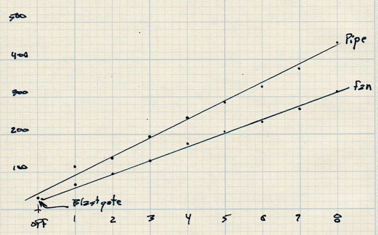
    The upper line is the duct fan mounted as in the picture and the lower line is the bare fan as measured on the bench.

    One might reasonably conclude something has gone horribly wrong, as the ductwork seems to contribute negative resistance and increased airflow. I think it’s a combination of the natural flow up the chimney, combined with a bit of flow straightening through the pipe directing air into the fan’s blades and measuring the (mostly uniform) inlet stream instead of the (somewhat segmented) outlet stream.

    Anyhow, the controller has eight speeds with surprisingly linear output. I doubt the upper line’s slope of 50 CFM/click means anything, but the consistency of both suggests a 4:1 flow range, from which I can pick the lowest speed that provides enough fume extraction.

    The basement has enough air leaking in (and out) that opening the exterior door had no discernible effect on the flow through the fan and up the chimney. At top speed the fan will produce two air changes per hour, chilling the basement something awful in the winter and introducing too much warm+moist air in the summer. This may call for a separate duct for outdoor makeup air, but that’s a problem for another season.

  • AC Infinity Fan Air Flow

    AC Infinity Fan Air Flow

    Being that type of guy, I had to measure the airflow through the inline duct fan intended for the soon-to-arrive laser cutter:

    CloudlIne Duct Fan - overview
    CloudlIne Duct Fan – overview

    The fan is on the inlet side:

    CloudlIne Duct Fan - inlet
    CloudlIne Duct Fan – inlet

    The outlet side consists of flow straightening blades around the backside of the motor mount:

    CloudlIne Duct Fan - outlet stator
    CloudlIne Duct Fan – outlet stator

    The duct ports on each end are (nominal) 6 inch, with the larger central body about 7 inch ID around the blank-faced 5 inch OD motor mount.

    I measured the air speed (in m/s) at the rim of the outlet port and at the center, with the rim speed about twice the center speed. The anemometer is an inch in diameter, so I assumed the annular flow was about 1.5 inch thick.

    Subtracting the dead zone in the middle from the total area of the fan body gives the area of the annulus carrying most of the moving air:

    Dia inchArea in^2Area ft^2
    Pipe6280.20
    Center370.05
    Annulus210.15

    Remember, the central dead zone isn’t quite dead: it has an air speed maybe half of the annulus.

    More spreadsheet action finds the flow for each of the fan speed settings:

    SpeedOuter m/sOuter ft/mUniform CFMAnnulus CFMInner ft/minInner CFMTotal CFMRated
    11.8354705217796144
    22.957111284286149888
    33.874814711037418129132
    44.996518914248224166176
    56.0118223217459129203220
    66.9135926720067933233264
    77.8153630222676838264308
    89.3183136027091645315351

    The Uniform CFM column assumes a uniform air flow through the whole pipe, which is obviously incorrect. The Total CFM equal to the sum of the Annulus and the Inner zone, which comes out pretty close to the Rated values in the last column, taken from a comment by the seller.

    Hard to believe I did the figuring before finding the “right” answers.

    This is, admittedly, in free air without ducts or elbows, so the results will be lower when everything gets hooked up.

  • Expedient Caster Wrench

    Expedient Caster Wrench

    Cranked down as far as it would go, a new adjustable height workbench in Mary’s sewing room turned out to be just slightly higher than the other work surfaces adjoining it, so I replaced its 3 inch casters with 2 inch versions:

    Sewing bench - 2 vs 3 inch casters
    Sewing bench – 2 vs 3 inch casters

    The bench arrived as a kit and included the 17 mm flat wrench required to snug the hex head on the 3/8-16 threaded stem atop the 3 inch caster against the bottom of the bench foot. The 2 inch caster also has a threaded stem, but of course it has a 14 mm hex head.

    I traced around a 14 mm open-end wrench on a scrap of aluminum and introduced the outline to Tiny Bandsaw:

    Improvised 14 mm caster wrench - rough cut
    Improvised 14 mm caster wrench – rough cut

    A little belt sander action cleaned up the outside, some hand filing matched the wrench to the hex, and it came out OK, even before I scrubbed the dirt off its white-ish pebble-finish coating:

    Improvised 14 mm caster wrench - finished
    Improvised 14 mm caster wrench – finished

    The bare steel wrench arrived with the bench and has 13 and 17 mm openings. I briefly considered embiggening the 13 mm end, but came to my senses.

    Aluminum isn’t a particularly good metal for wrench duty, but this one had to apply maybe 1/3 of a turn to each of four stems, stopping when snug, and it performed just fine. It’s now sleeping in the wrench drawer, dreaming of another job that may never arrive.

    The smaller casters lowered the bench by about an inch, whereupon cranking the surface up a bit less than half an inch aligned it perfectly.

  • Wireless Numeric Keypad vs. AmazonBasics AAA Alkaline: Another Data Point

    Wireless Numeric Keypad vs. AmazonBasics AAA Alkaline: Another Data Point

    Looks like a trend to me:

    Wireless keypad - 6 year battery
    Wireless keypad – 6 year battery

    Of course, past performance does not guarantee future results, because Amazon surely has gone through more white-label suppliers in the last half-dozen years than I can count.

  • Work Glove Security Tags

    Work Glove Security Tags

    Having worn my work glove collection to exhaustion, the fanciest two pairs in a new selection came with elaborate security tags:

    Elaborate Security Tag dissection
    Elaborate Security Tag dissection

    Finding a standard tag inside inside the fancy shell shouldn’t come as any surprise, but I’m surprised the retail loss ratio for a pair of $20 gloves can support that much hardware.

    I went through the self-checkout area and didn’t do anything special, so either those lanes don’t have tag scanners or the tags are security theater.

  • Gidget II Sewing Table: Temporary Juki Insert

    Gidget II Sewing Table: Temporary Juki Insert

    Mary’s new sewing table just arrived, but the laser-cut acrylic insert fitting around her Juki sewing machine is still a month or two away. Until then, a simple cardboard replacement must suffice to fill the gap:

    Juki temporary table insert
    Juki temporary table insert

    The rectangle just to the left of the needle is a hatch for bobbin changes. Sheer faith and an interference fit between layers of Kapton tape holds it in place with surprising force.

    I wanted to tape the cardboard edges to the machine and the table to smooth out the transitions, but her Supreme Slider slippery sheet may solve the problem without adhesives:

    Juki temporary table insert - Super Slider
    Juki temporary table insert – Super Slider

    The “insert” is a 1/4 inch thick double-layer corrugated cardboard sheet, utility-knifed from a huge box. She layers cardboard under the wood chips in her Vassar Farms garden paths to discourage the weeds; this seemed like a perfectly reasonable diversion.

  • CNC-3018XL X-Axis Recalibration

    CNC-3018XL X-Axis Recalibration

    Plotting the backlash / calibration target on both the CNC-3018XL and the MPCNC quickly showed, contrary to what I expected, the MPCNC was dead-on accurate, albeit with some wobbulation and a trace of backlash:

    MPCNC - Backlash test - detail
    MPCNC – Backlash test – detail

    Although it looks ug-u-lee, the (lower speed) drag knife cuts come out nice and, because the entry and exit moves match the main cut, the minimal backlash wasn’t a problem.

    Turns out only the X axis on the 3018XL had a problem:

    Cal Target - 400 step-mm - merged
    Cal Target – 400 step-mm – merged

    Apparently the longer leadscrew I installed as part of the “XL” conversion has a small thread pitch error: about 1 mm short in every 250 mm of travel. I don’t have any (definite, non-handwavy) method to measure the pitch directly, other than by running the follower nut and measuring the results, but it’s consistently short.

    Quite some time ago (after blowing up the OEM controller board), I set up the Protoneer CNC board in 1:8 microstep mode, making the GRBL $100 setting a nice, round 400 step/mm for a two-start leadscrew with 2 mm pitch and 4 mm lead:

    400 step/mm = (200 step/rev * 8 µstep/step) / 4 mm 

    After a few more measurements suggesting the leadscrew actually traveled 249.2 mm, the correct value will be:

    401.28 step/mm = 400 step/mm × 250 mm / 249.2 mm

    To verify I understood the problem and solution, I set $100 to a few integer values around the goal:

    Cal Target - stacked - 399-402 step-mm
    Cal Target – stacked – 399-402 step-mm

    The top image shows the leftmost line at the 10 mm mark on the scale, because it’s easier for me to match the ink line with an engraved line, rather than the non-line at the end of the ruler.

    The other images show the results for $100 set to 399, 400, 401, and 402 step/mm, respectively. The results last two results bracket the desired 250 mm outcome, with 401 step/mm being Close Enough™. GRBL accepts a floating point step/mm value, so I set $100 to 401.28, but I was unable to convince myself the result came out consistently different than 401.00.

    Plotting both the tick marks (green) and the knife path (red) on the 3018XL, then cutting the bare paper on the MPCNC, showed the two machines now agree on where the knife should fall. The outer end of the tick marks extends 1 mm beyond the cut line to ensure small misalignments do not produce an obvious white gap around the edge of the deck.

    The Y axis continues to match:

    Tek CC - 2022-02-14 - Y detail
    Tek CC – 2022-02-14 – Y detail

    And now the X axis looks just as good:

    Tek CC - 2022-02-14 - X detail
    Tek CC – 2022-02-14 – X detail

    The drag knife corners are rounded, as you’d expect. The cut seems slightly offset from a small origin touch-off error, but the scales now match.