
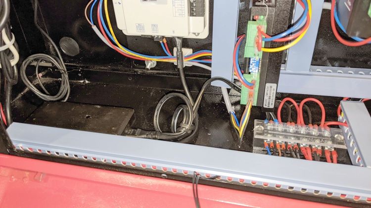
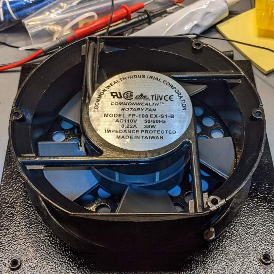
The OMTech 60 W laser gets its air assist from an aquarium-style air pump in the right rear of the cabinet:
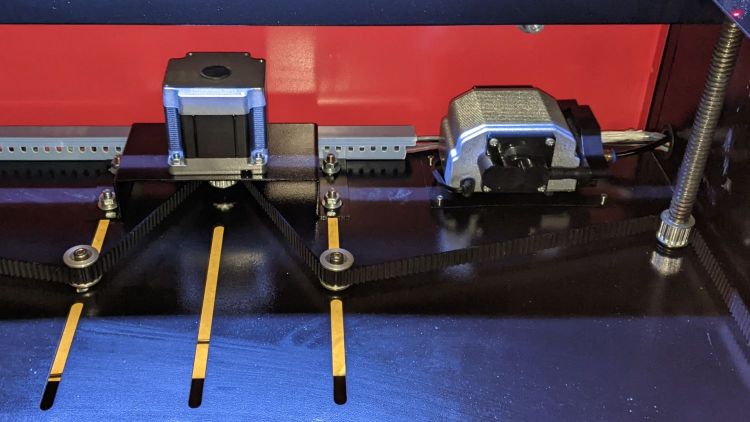
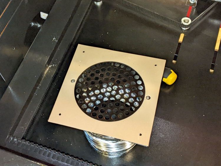
Since that picture, I’ve sealed the slots for the Z-axis belt tensioner pulleys.
The pump is connected directly to the AC line at the main barrier block (blue and brown on leftmost two terminals):
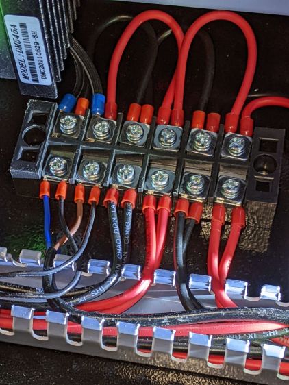
Even though the pump has very flexy rubber feet, it’s annoyingly noisy and should be off when the laser beam is off.
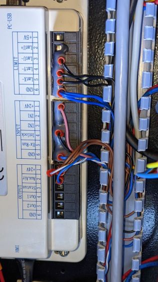
The knockoff RuiDa KT332N controller (possibly by Ryxon, based on a LightBurn forum thread, but without a visible name anywhere on the hardware or in the manual) has an Aux.Air output terminal:
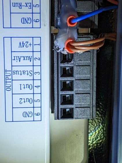
Yes, the controller is mounted that way inside the electronics bay.
Chipping away the hot-melt glue over the terminals lets you pry the terminal block out of the controller:
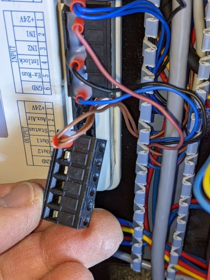
The KT332N manual describes the Aux.Air pin 2 function:
| Dedicated output. When auxiliary air control is enabled, this port outputs a control signal to control the valve or other relay to release auxiliary air. This port is multiplexed with pen control signal. When auxiliary air control is disabled, this port is assigned as pen control. The output type is open collector. The output can be set to be synchronized with laser or synchronized with work. |
The word “pen” does not occur anywhere else in the manual, so I have no idea what it might mean. Perhaps the controller can also become a pen plotter?
A configuration screen (Menu → Para Setting → Auxi.Air) gives the options:
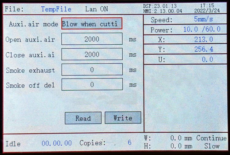
Section 9.2 of the manual describes the choices, although not quite in the same words:
- Blowing method:The way of the air is blown during processing. Can be configured to output fire, process gas, and manual gas.
- Blow on delay:Delay time after turning on air blowing
- Blow off delay:Delay time before turning off the blow
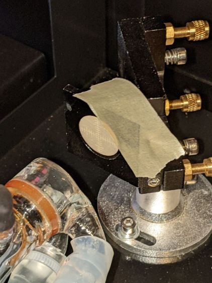
Section 7.2 gives the electrical parameters:
| All output signals of this controller are output based on opto-coupler isolation technology and OC gate output. Its maximum driving capacity is 300mA, which can directly drive 6V / 24V relays, light-emitting indicators, buzzer alarm devices, etc. |
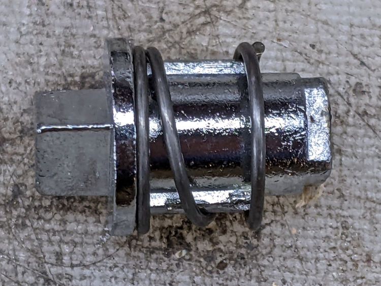
I wired an AC solid state relay (surely a counterfeit Fotek) in series with the pump’s AC Line wire:
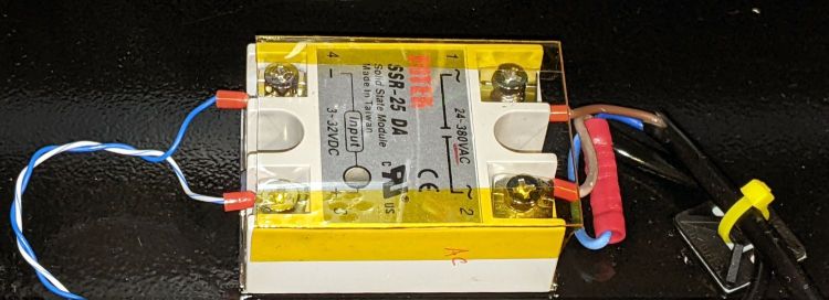
It’s firmly stuck to the bottom of the electronics bay with heatsink tape, not that it gets particularly warm switching a few dozen watts of pump.
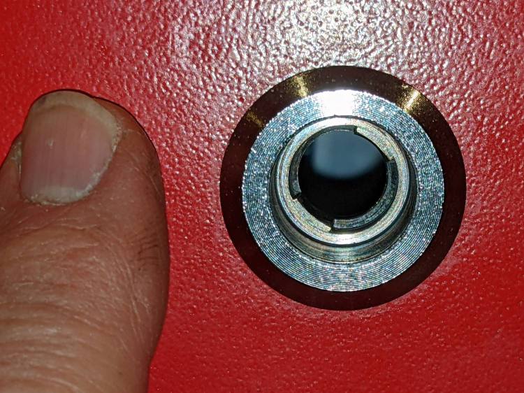
Because the output pin is active low, the SSR + input comes from a ferrule jammed into the 24 V supply pin on the controller, along with the original ferrule holding three other wires:
With all that in place, I turned it on and … the air pump did not turn on when I ran the next job. I could manually turn the pump on with the front panel Aux Air button, but it shut off as soon as I ran a file.
The “enable” setting referred to in Section 4.6 appears in the Vendor Parameters:
| Enable the auxiliary air control : If you want to use the Wind signal of the output port to control the fan switch in layers, you must enable this parameter. Otherwise, the Wind signal outputs other signals. |
The Vendor Settings are protected by a password I don’t know do not appear in the section of settings I assumed they would be in, based on the manual’s wording. It seems an external program connected to the controller by USB or the network provides the only way to access these settings.
Fortunately, LightBurn exposes the Vendor settings after you click through a warning dialog:
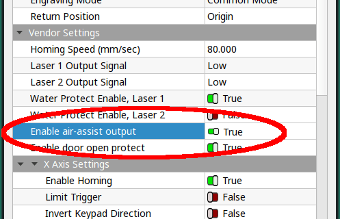
And then It Just Works™.
The “Blow when laser” option turns on the pump whenever the laser power supply is producing a beam, so it switches on and off at a furious pace. This is not the option you are looking for.


