The Smell of Molten Projects in the Morning

Ed Nisley's Blog: Shop notes, electronics, firmware, machinery, 3D printing, laser cuttery, and curiosities. Contents: 100% human thinking, 0% AI slop.

Tag: Sherline

Sherline CNC mill

  • Laser Cutter: Improving the Red-Dot Pointer

    Laser Cutter: Improving the Red-Dot Pointer

    The red-dot pointer on the OMTech laser cutter has the same problem as my laser aligner for the Sherline mill: too much brightness creating too large a visual spot. In addition, there’s no way to make fine positioning adjustments, because the whole mechanical assembly is just a pivot.

    The first pass involved sticking a polarizing filter on the existing mount while I considered the problem:
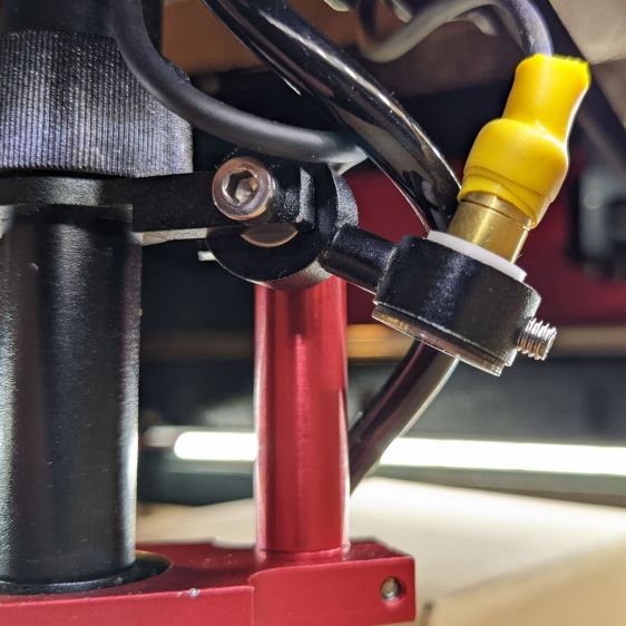
    OMTech red dot pointer - polarizing filter installed
    OMTech red dot pointer – polarizing filter installed

    The red dot pointer module is 8 mm OD and the ring is 10 mm ID, but you will be unsurprised to know the laser arrived with the module jammed in the mount with a simple screw. Shortly thereafter, I turned the white Delrin bushing on the lathe to stabilize the pointer and installed a proper setscrew, but it’s obviously impossible to make delicate adjustments with that setup.

    Making the polarizing filter involves cutting three circles:
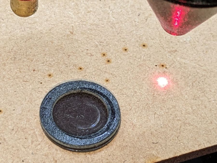
    OMTech red dot pointer - polarizing filter
    OMTech red dot pointer – polarizing filter

    Rotating the laser module in the bushing verified that I could reduce the red dot to a mere shadow of its former self, but it was no easier to align.

    Replacing the Delrin bushing with a 3D printed adjuster gets closer to the goal:
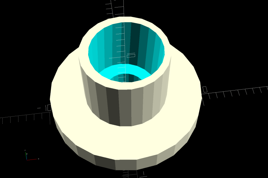
    Pointer fine adjuster - solid model
    Pointer fine adjuster – solid model

    Shoving a polarizing filter disk to the bottom of the recess, rotating the laser module for least brightness, then jamming the module in place produces a low-brightness laser spot.

    The 8 mm recess for the laser module is tilted 2.5° with respect to the Y axis, so (in principle) rotating the adjuster + module (using the wide grip ring) will move the red dot in a circle:
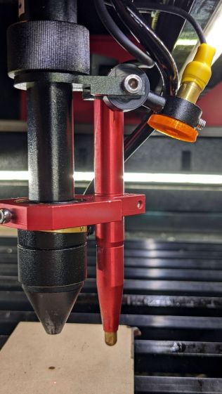
    Improved red-dot pointer - overview
    Improved red-dot pointer – overview

    The dot sits about 100 mm away at the main laser focal point, so the circle will be about 10 mm in diameter. In practice, the whole affair is so sloppy you get what you get, but at least it’s more easily adjusted.

    The M4 bolt clamping the holder to the main laser tube now goes through a Delrin bushing. I drilled out the original 4 mm screw hole to 6 mm to provide room for the bushing:
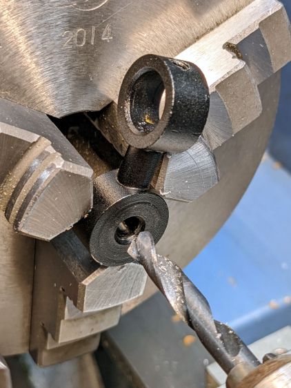
    Improved red-dot pointer - drilling bolt hole
    Improved red-dot pointer – drilling bolt hole

    The bushing has a wide flange to soak up the excess space in the clamp ring:
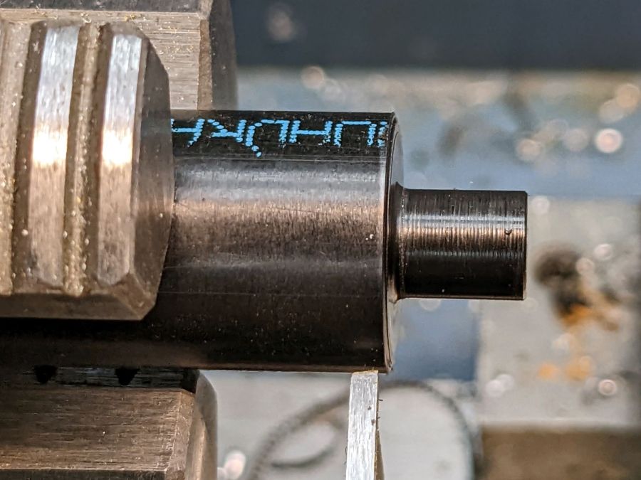
    Improved red-dot pointer - turning clamp bushing
    Improved red-dot pointer – turning clamp bushing

    With all that in place, the dimmer dot is visually about 0.3 mm in diameter:
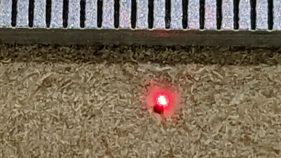
    Improved red-dot pointer - offset
    Improved red-dot pointer – offset

    The crappy image quality comes from excessive digital zoom. The visible dot on the MDF surface is slightly larger than the blown-out white area in the image.

    The CO₂ laser hole is offset from the red laser spot by about 0.3 mm in both X and Y. Eyeballometrically, the hole falls within the (dimmed) spot diameter, so this is as good as it gets. I have no idea how durable the alignment will be, but it feels sturdier than it started.

    Because the red dot beam is 25° off vertical, every millimeter of vertical misalignment (due to non-flat surfaces, warping, whatever) shifts the red dot position half a millimeter in the XY plane. You can get a beam combiner to collimate the red dot with the main beam axis, but putting more optical elements in the beam path seems like a Bad Idea™ in general.

    The OpenSCAD source code as a GitHub Gist:

    // Laser cutter red-dot module fine adjust
    // Ed Nisley KE4ZNU 2022-09-22
    Layout = "Show"; // [Build, Show]
    /* [Hidden] */
    ThreadThick = 0.25;
    ThreadWidth = 0.40;
    HoleWindage = 0.2;
    Protrusion = 0.1; // make holes end cleanly
    inch = 25.4;
    ID = 0;
    OD = 1;
    LENGTH = 2;
    function IntegerMultiple(Size,Unit) = Unit * ceil(Size / Unit);
    //———————-
    // Dimensions
    PointerOD = 8.0 + 0.2; // plus loose turning fit
    Aperture = 5.0; // clear space for lens
    SkewAngle = 2.5;
    MountRing = [10.0,16.0,8.0]; // OEM laser module holder
    GripRim = [Aperture,MountRing[OD] + 2*1.5,3.0]; // finger grip around OD
    NumSides = 24;
    //———————-
    // Useful routines
    module PolyCyl(Dia,Height,ForceSides=0) { // based on nophead's polyholes
    Sides = (ForceSides != 0) ? ForceSides : (ceil(Dia) + 2);
    FixDia = Dia / cos(180/Sides);
    cylinder(r=(FixDia + HoleWindage)/2,
    h=Height,
    $fn=Sides);
    }
    //———————-
    // Holder geometry
    module Holder() {
    difference() {
    union() {
    cylinder(d=GripRim[OD],h=GripRim[LENGTH],$fn=NumSides);
    PolyCyl(MountRing[ID],MountRing[LENGTH] + GripRim[LENGTH],NumSides);
    }
    translate([0,0,-Protrusion]) // close enough without skew angle
    PolyCyl(Aperture,2*MountRing[LENGTH],NumSides);
    translate([0,0,MountRing[LENGTH]/2 + GripRim[LENGTH]])
    rotate([0,SkewAngle,0])
    translate([0,0,-MountRing[LENGTH]/2])
    PolyCyl(PointerOD,2*MountRing[LENGTH],NumSides);
    }
    }
    //———————-
    // Build it
    if (Layout == "Show") {
    Holder();
    }
    if (Layout == "Build") {
    Holder();
    }

  • Acrylic Coasters: Edge Finishing, Round 4

    Acrylic Coasters: Edge Finishing, Round 4

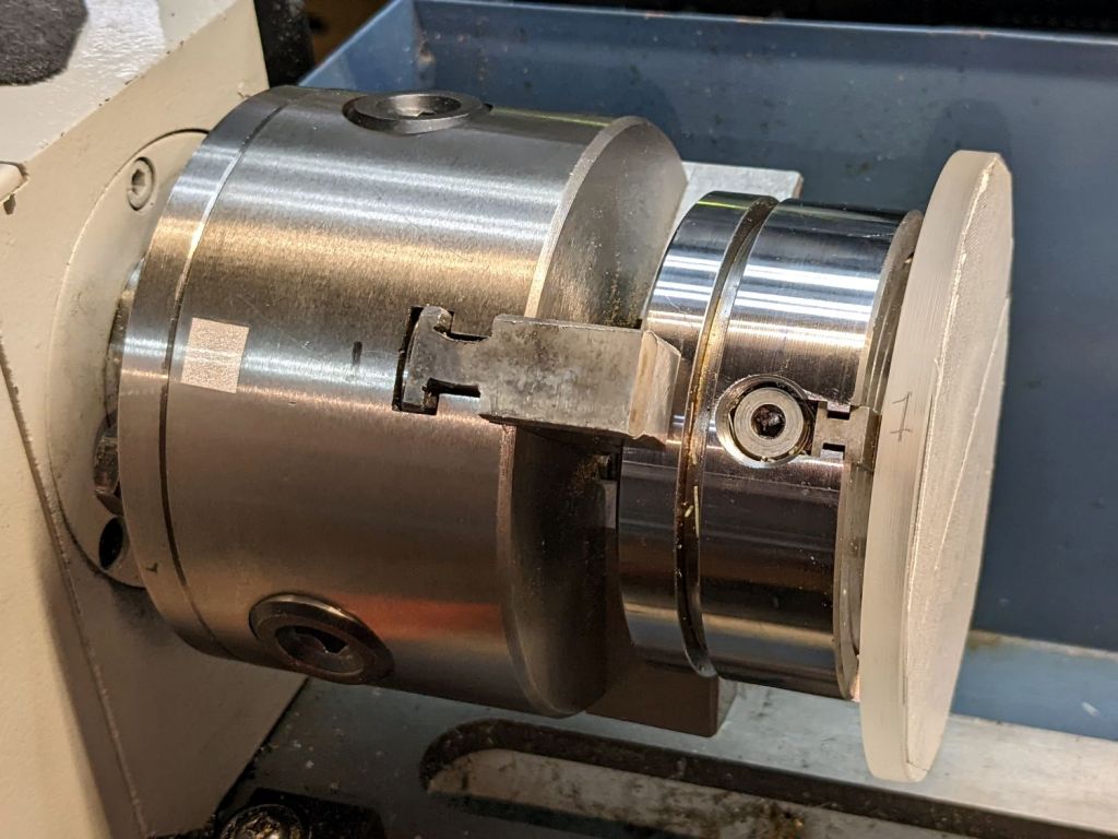
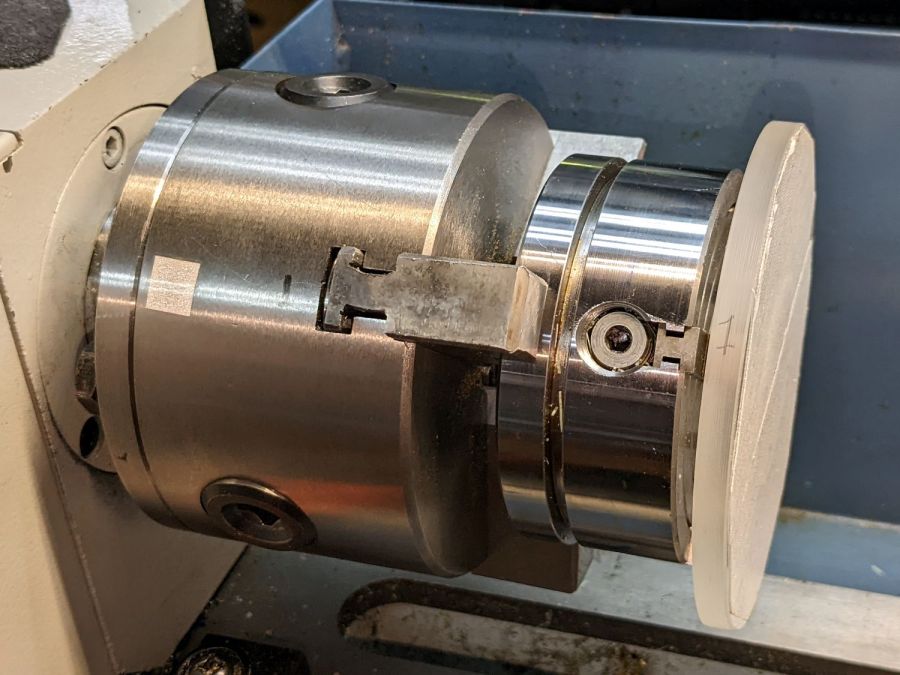
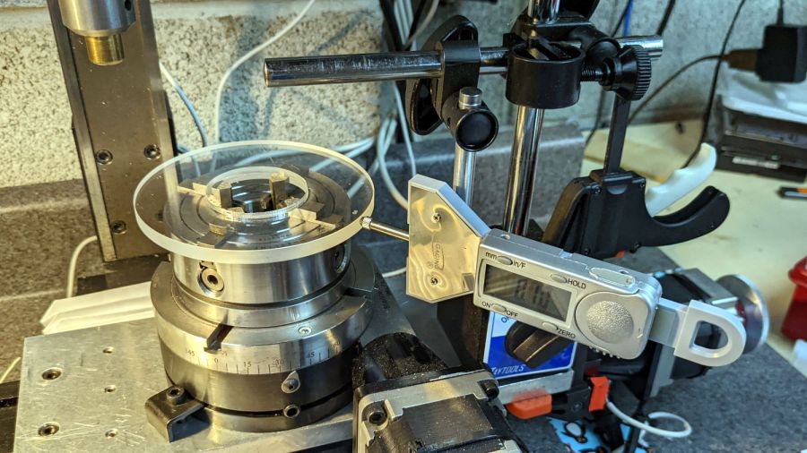
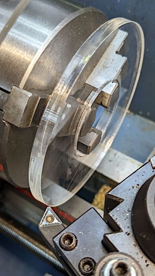
    Lacking a 4-jaw chuck for the lathe, this should suffice:

    Coaster Epoxy Rim - chuck-in-chuck setup
    Coaster Epoxy Rim – chuck-in-chuck setup

    Which is just the Sherline 4-jaw chuck chucked in the lathe’s 3-jaw chuck, with both chuck Jaw 1 positions lined up and marked on the acrylic disk fixture. The picture is a recreation set up after the fact, because I lack a good picture of the overall scene.

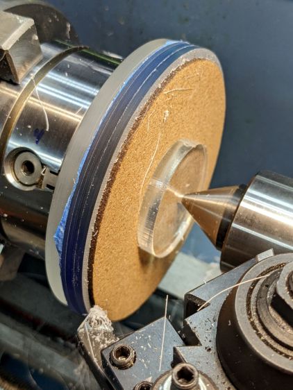
    Now it’s easy enough to center the fixture, stick the coaster in place with reasonable accuracy, then tweak the Sherline chuck to center the coaster:

    Coaster Epoxy Rim - turning setup
    Coaster Epoxy Rim – turning setup

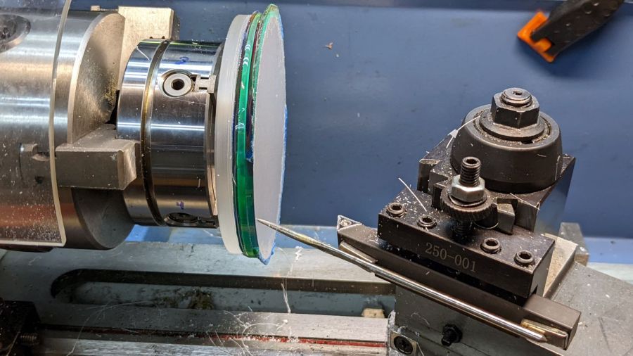
    Because the bottom layer is a laser-cut disk, eyeballometrically aligning its edge to a simple pointer worked surprisingly well:

    Coaster Epoxy Rim - locating mirror edge
    Coaster Epoxy Rim – locating mirror edge

    Turning the OD down to match the bottom disk meant I could finally get decent results with zero drama:

    Coaster Epoxy Rim - turned samples
    Coaster Epoxy Rim – turned samples

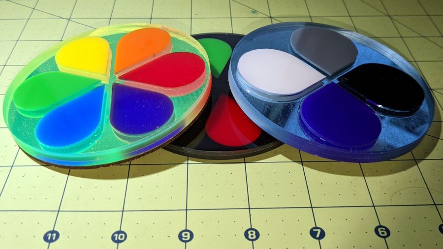
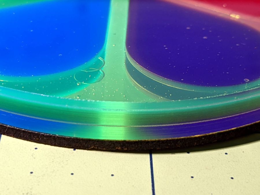
    From the bottom, this one has a 3 mm mirror, the 3 mm fluorescent green frame + petals, and a 1.6 mm top sheet:

    Coaster Epoxy Rim - turned 6 petal mirror
    Coaster Epoxy Rim – turned 6 petal mirror

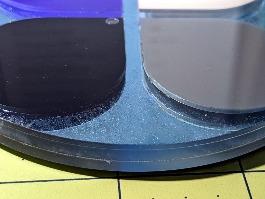
    This one has a 3M double-sided tape with low-surface-energy adhesive layers between the mirror and the fluorescent blue frame + petal, with epoxy between the top layer and the frame.

    Coaster Epoxy Rim - turned 4 petal
    Coaster Epoxy Rim – turned 4 petal

    If I never tell anybody, they’ll think the slightly granular look of the tape was deliberate; it looks OK to me.

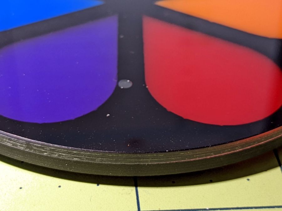
    And, for completeness, the crash test dummy from the start of this adventure:

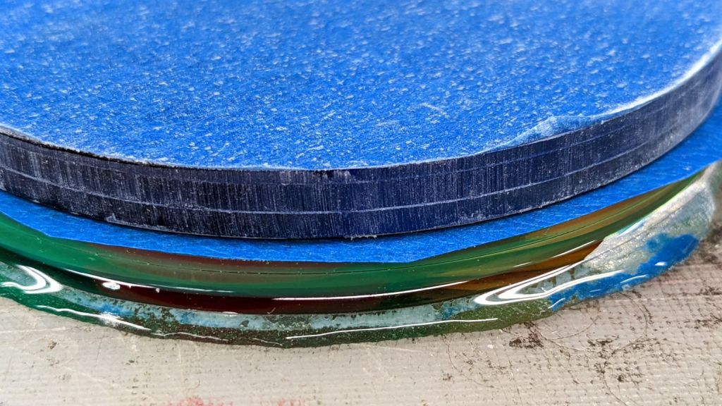
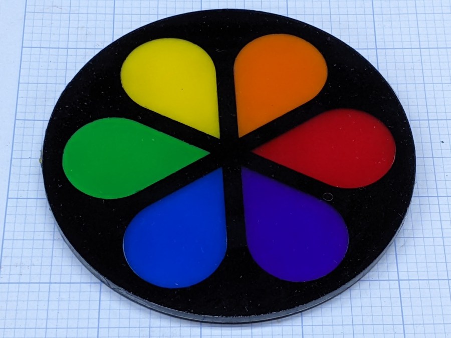
    Coaster Epoxy Rim - turned 6 petal black
    Coaster Epoxy Rim – turned 6 petal black

    I don’t know how to avoid the bubbles, as the usual torch-the-top and pull-a-vacuum techniques pop bubbles at the epoxy-air interface. These bubbles are trapped under the top acrylic sheet, even though I was rather painstaking about easing the layer down from one side to the other while chasing bubbles along.

    Maybe I can define bubbles as Part of the Art?

    Definitely fancier than chipboard, although not nearly as absorbent.

  • Acrylic Coasters: Edge Finishing, Round 2

    Acrylic Coasters: Edge Finishing, Round 2

    Because the Sherline mill can’t cut all the way around a 4 inch OD coaster clamped to its table, I set up the 4-jaw chuck on the rotary table and centered the nicely round fixture:

    Coaster Epoxy Rim - centering fixture plate
    Coaster Epoxy Rim – centering fixture plate

    Admittedly, the centering need not be so precise, but practice makes perfect.

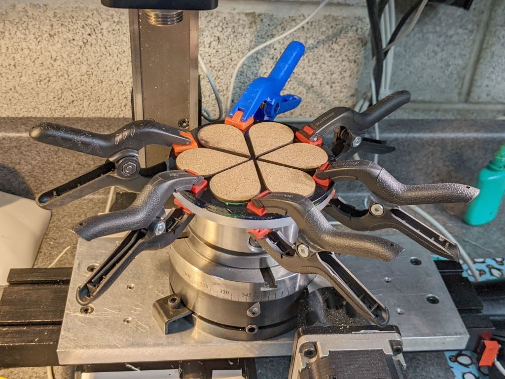
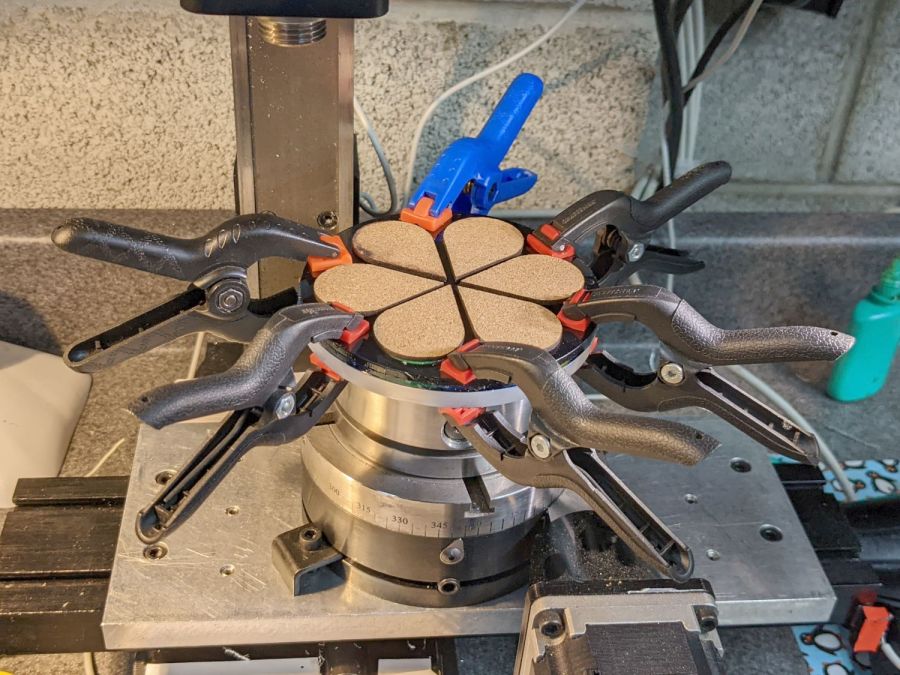
    A few strips of double-stick tape affixed the test coaster, with too many clamps applied to settle it in place:

    Coaster Epoxy Rim - Sherline clamp setup
    Coaster Epoxy Rim – Sherline clamp setup

    A few sissy cuts demonstrated the tape lacked sufficient stickiness to hold the coaster in place against the milling cutter’s uplift. I managed to mill most of the perimeter with those clamps in place, moving each one from just ahead of the cutter to just behind the cutter.

    That way lies both madness and organic damage.

    There are better tapes and better adhesives, all trading off a really sticky fixture against difficulty extracting an undamaged part.

    A more complex circular fixture with built-in mechanical edge clamps extending around a major part of the perimeter seems like entirely too much of a diversion for a couple of obscene-gerund coasters.

    A live center in a lathe tailstock applies pressure in exactly the right place to hold a circular object against a fixture while slicing off the entire perimeter, with the only problem being centering the object.

    Maybe shimming the fixture against one chuck jaw will suffice?

  • Acrylic Coasters: Edge Finishing, Round 1

    Acrylic Coasters: Edge Finishing, Round 1

    Assembling acrylic pieces inside an epoxy-filled frame produces nice results:

    Cut Acrylic Coaster - bottom
    Cut Acrylic Coaster – bottom

    The gotcha: epoxy oozes from between the layers to form a slobbery edge.

    I tried introducing a similar coaster to Mr Disk Sander with reasonable results:

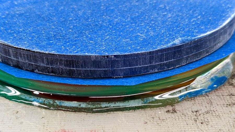
    Coaster Epoxy Rim - disk sanded rim
    Coaster Epoxy Rim – disk sanded rim

    The coaster on the bottom has its original generous epoxy slobber around the acrylic disks.

    Assembling the layers inside a mold seems fraught with messiness, particularly if I eventually want to get it out of the mold.

    Using a finer abrasive disk would certainly help, but the whole process requires intense concentration and is utterly unforgiving of mistakes.

    I figured I could attach the coaster to a lathe fixture and turn the rim, so I made a fixture from scrap acrylic:

    Coaster Epoxy Rim - cutting fixture plate
    Coaster Epoxy Rim – cutting fixture plate

    The lathe chuck inside jaws fit inside the hole and I set up to turn the OD to a nice even diameter:

    Coaster Epoxy Rim - turning fixture rim
    Coaster Epoxy Rim – turning fixture rim

    The fixture sat flush against the middle step of the jaws with plenty of clearance from the outer step, so I could turn the OD without whacking the carbide insert.

    I planned to grab the OD and turn the ID to a (reasonably) concentric finish, but the outer jaws have an absolute diameter limit a few millimeters less than the 4 inch = 101.4 mm coaster OD.

    After some increasingly desperate attempts, I concluded that, lacking a 4-jaw lathe chuck, there was no way to mount the coaster on the fixture and have it sit it even approximately centered on the spindle axis.

    I do, however, have a 4-jaw chuck for the Sherline mill, normally used with the rotary table.

    Next up: Round 2.

  • High Impact Art: Smashed Glass Coaster Meniscus Removal

    High Impact Art: Smashed Glass Coaster Meniscus Removal

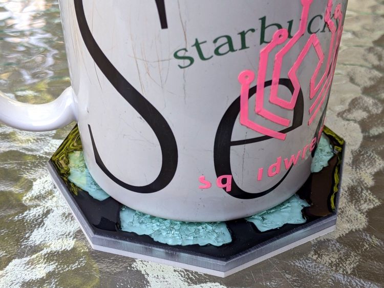
    After using the smashed glass coaster for a while, the beveled epoxy meniscus around the perimeter proved itself more annoying than expected:

    Glass Coaster - second test
    Glass Coaster – second test

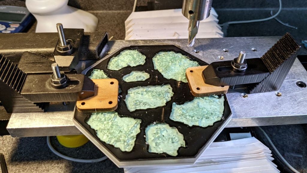
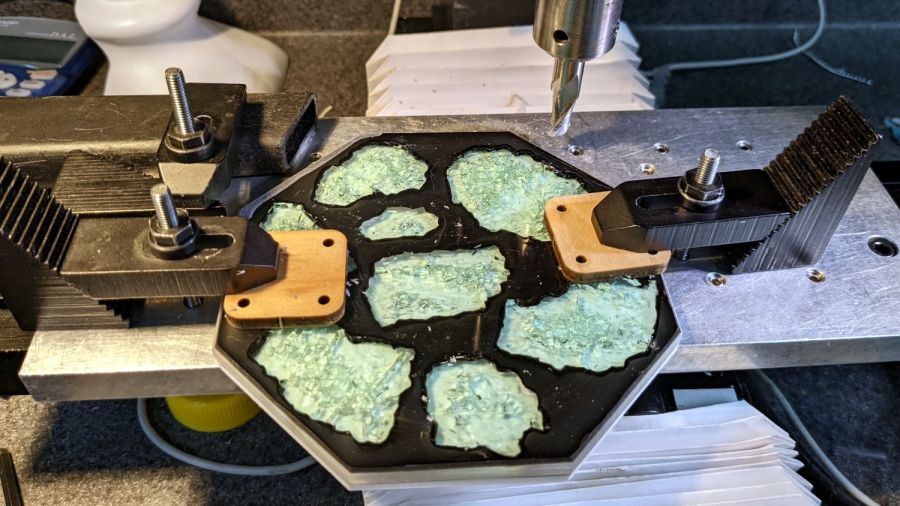
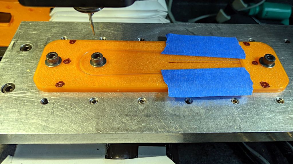
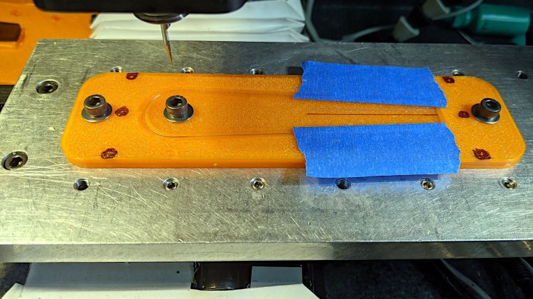
    So I clamped it to the Sherline’s tooling plate and milled off the rim:

    Smashed Glass Coaster - meniscus removal
    Smashed Glass Coaster – meniscus removal

    Given the Sherline’s cramped work envelope, all the action took place along the rearmost edge, requiring eight reclampings indexed parallel to the table with a step clamp.

    The cutter cleared off everything more than 0.3 mm above the surface of the glass chunks. I could probably have gone another 0.1 mm lower, but chopping the bit into the edge of a shattered glass fragment surely wouldn’t end well.

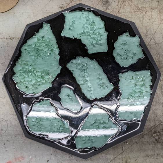
    Polishing the dark gray milled surface might improve it slightly, at the risk of scuffing whatever poured epoxy stands slightly proud of the glass:

    Smashed Glass Coaster - leveled edge
    Smashed Glass Coaster – leveled edge

    Perhaps if I define it to be a border, everybody will think it was intentional.

  • Homage Tektronix Circuit Computer: Laser-Engraved Hairline Tests

    Homage Tektronix Circuit Computer: Laser-Engraved Hairline Tests

    This worked out surprisingly well:

    Tek CC - laser-etched cursor hairline
    Tek CC – laser-etched cursor hairline

    Not knowing what to expect, I peeled the protective plastic off the styrene PETG sheet before cutting the perimeter, thereby dooming myself to about five minutes of polishing with Novus 2 to remove the condensed vaopor and another five minutes restoring the shine with Novus 1. Next time, I’ll know better.

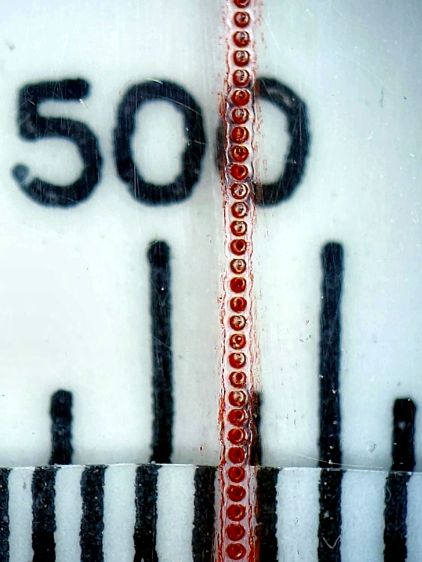
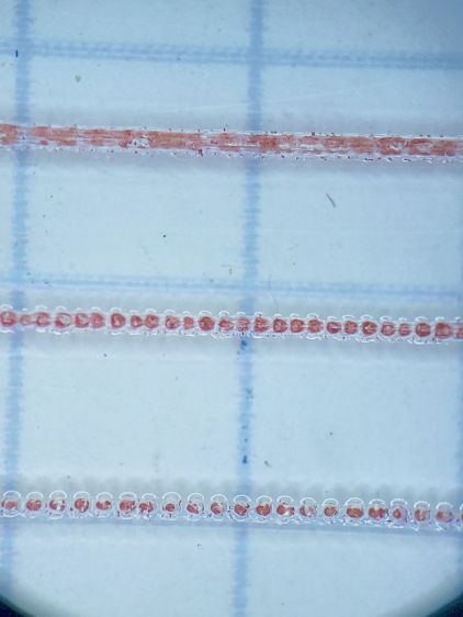
    Eyeballometrically, the hairline is a lovely fine line, but it’s really a series of craters on 0.25 mm centers filled with red Pro Sharpie marker and wiped off with denatured alcohol:

    Tek CC - laser-etched cursor hairline - detail
    Tek CC – laser-etched cursor hairline – detail

    That’s dot mode: 2 ms pulses at 20% power (about 12 W) with a line speed of 100 mm/s and 0.25 mm dot spacing. The craters look to be 0.15 mm in diameter, with a 0.15 mm blast radius merging into a line along the sides. The view is looking through the undamaged side of the cursor, so you’re seeing the craters from their tips.

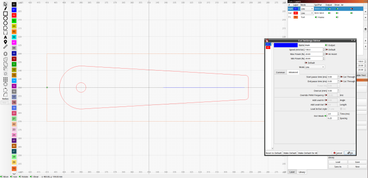
    I cut the cursor and engraved / etched the hairline in one operation, by just laying a rectangle on the honeycomb and having my way with it:

    Tek CC Cursor - LightBurn layout
    Tek CC Cursor – LightBurn layout

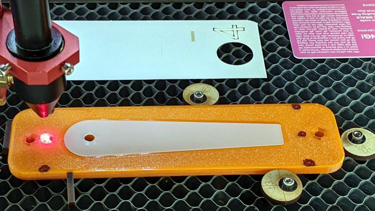
    For a more systematic test I aligned a cursor engraving fixture I built for the Sherline atop the laser’s honeycomb platform and wedged it into place with eccentric stops, then dropped a cursor milled on the Sherline in place:

    Tek CC Cursor - laser fixture alignment
    Tek CC Cursor – laser fixture alignment

    The six pips (small printed holes with ugly black outlines) intended for the Sherline’s laser aligner make this feasible, although the accuracy of the OMTech’s laser pointer requires precisely setting the focal point atop the fixture.

    The corners of LightBurn’s tooling layer (the enclosing rectangle) match the corner pip positions, so framing the pattern should light up those four holes. Putting the Job Origin (small green square) at the center-left point lets me tweak the machine’s origin to drop the alignment laser into that pip.

    AFAICT, burning a cute puppy picture pretty close to the middle of a slate coaster makes everybody else deliriously happy.

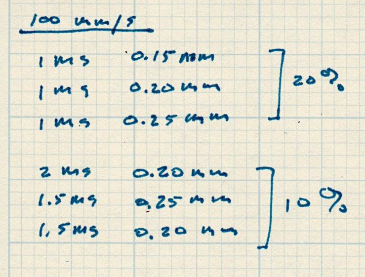
    Setting up the cut layer parameters:

    Tek CC Cursor - laser dot mode tests
    Tek CC Cursor – laser dot mode tests

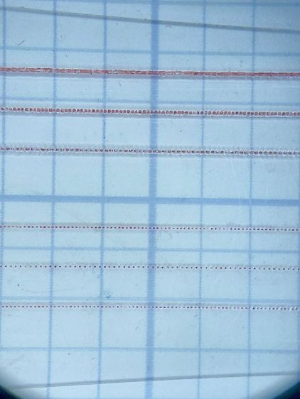
    Burning through the protective film, peeling it off, filling with Sharpie, and wiping with alcohol produces interesting results against a 0.1 inch = 2.54 mm grid:

    Tek CC Cursor - dot mode 1-2ms 10-20pct
    Tek CC Cursor – dot mode 1-2ms 10-20pct

    The angled top and bottom lines are the edges of the cursor, positioned with the craters on the top surface.

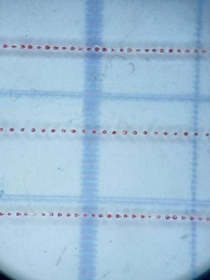
    The bottom three lines at 10% power consist of distinct 0.10 mm craters incapable of holding much ink:

    Tek CC Cursor - dot mode 2ms 10pct
    Tek CC Cursor – dot mode 2ms 10pct

    The top three lines at 20% power have 0.15 mm craters and look better:

    Tek CC Cursor - dot mode 1ms 20pct
    Tek CC Cursor – dot mode 1ms 20pct

    The top line was a complete surprise: it seems a 20% duty cycle does not turn off completely between 1 ms dots spaced at 0.15 mm. I expected a row of slightly overlapping dots, which is obviously not what happens.

    Punching the dots through the protective film eliminated the polishing operation, although I have yet to cut the perimeter with the film in place.

    More experimentation is in order, but it looks like I can finally engrave good-looking and perfectly aligned hairlines on nicely cut cursors without all those tedious manual machining operations.

    [Update: dot mode can produce a continuous trench that looks even better! ]

  • Sheath Your Blades!

    Sheath Your Blades!

    Trigger warning: gore.

    A week ago I milled a stack of cursor blanks, then engraved a test hairline on a scrap cursor to make sure everything was ready:

    Cursor V-bit setup
    Cursor V-bit setup

    After raising the spindle a few inches, I reached across the table, peeled the tape, and, as I pulled my hand back with the finished cursor, snagged the back of my left index finger on the V bit.

    So. Much. Blood.

    Urgent Care PA: “You may have nicked the tendon. Get thee hence to the Hospital Trauma Center.”

    Trauma Center MD: “See that white fiber down in there? That’s the extensor ligament. Looks OK and should heal fine.”

    Me: “Urp.”

    Trauma Center MD: “Unless you’re one of the 20% who get an infection.”

    Me: “Unless I’m one of the few who contract an MRSA infection, then just up and die.”

    Trauma Center MD: “Well, yes, there’s that. If the wound swells or smells bad, come back here quickly.”

    Dutchess County is now on the trailing edge of the Omicron wave, but the Trauma Center is attached to the Emergency Room and had a steady stream of customers arriving by ambulance. While being entirely content to not be their most urgent case, I had plenty of time to examine the wide variety of instruments parked in the room with me:

    Nameless Hospital Cart
    Nameless Hospital Cart

    I’m on a ten-day regimen of surprisingly inexpensive Amoxicillin + Clavulanate Potassium capsules, which is apparently what it takes to knock down a potential infection these days.

    Five days later, it looks like I should pull through:

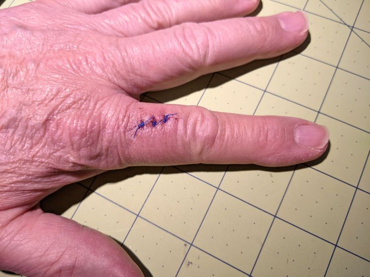
    Lacerated Left Index Finger
    Lacerated Left Index Finger

    So I hereby swear a mighty oath on the bones of my ancestors to always sheath my blades. You should, too.

    But we all knew that last week, didn’t we?