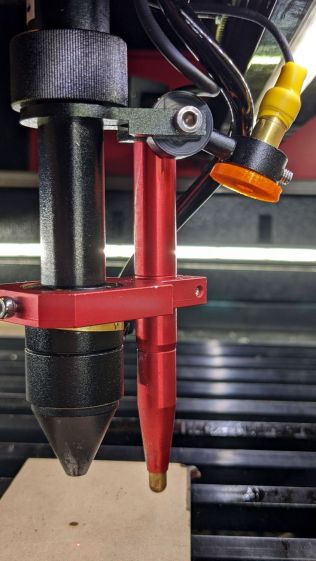
The red-dot pointer on the OMTech laser cutter has the same problem as my laser aligner for the Sherline mill: too much brightness creating too large a visual spot. In addition, there’s no way to make fine positioning adjustments, because the whole mechanical assembly is just a pivot.
The first pass involved sticking a polarizing filter on the existing mount while I considered the problem:
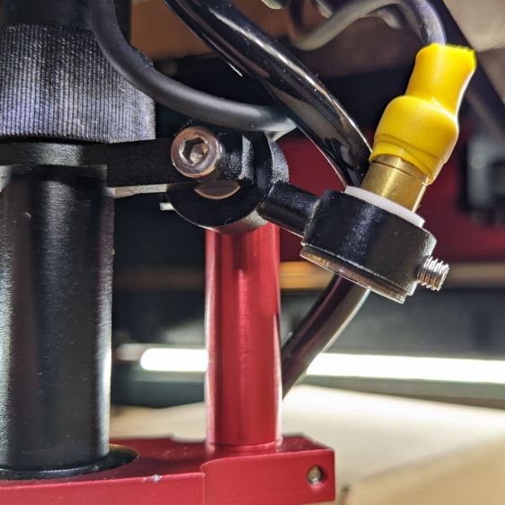
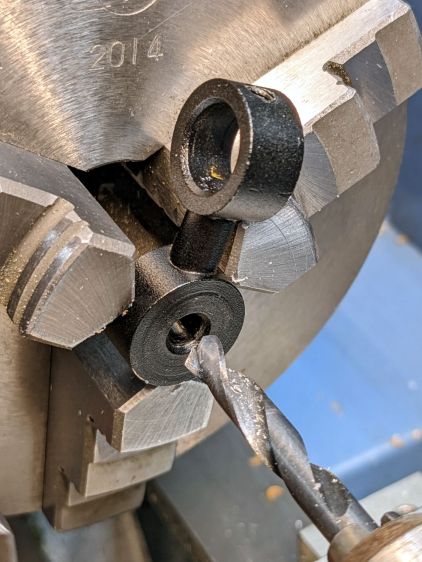
The red dot pointer module is 8 mm OD and the ring is 10 mm ID, but you will be unsurprised to know the laser arrived with the module jammed in the mount with a simple screw. Shortly thereafter, I turned the white Delrin bushing on the lathe to stabilize the pointer and installed a proper setscrew, but it’s obviously impossible to make delicate adjustments with that setup.
Making the polarizing filter involves cutting three circles:
Rotating the laser module in the bushing verified that I could reduce the red dot to a mere shadow of its former self, but it was no easier to align.
Replacing the Delrin bushing with a 3D printed adjuster gets closer to the goal:
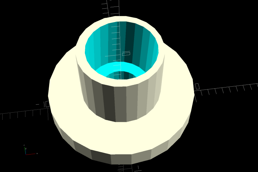
Shoving a polarizing filter disk to the bottom of the recess, rotating the laser module for least brightness, then jamming the module in place produces a low-brightness laser spot.
The 8 mm recess for the laser module is tilted 2.5° with respect to the Y axis, so (in principle) rotating the adjuster + module (using the wide grip ring) will move the red dot in a circle:
The dot sits about 100 mm away at the main laser focal point, so the circle will be about 10 mm in diameter. In practice, the whole affair is so sloppy you get what you get, but at least it’s more easily adjusted.
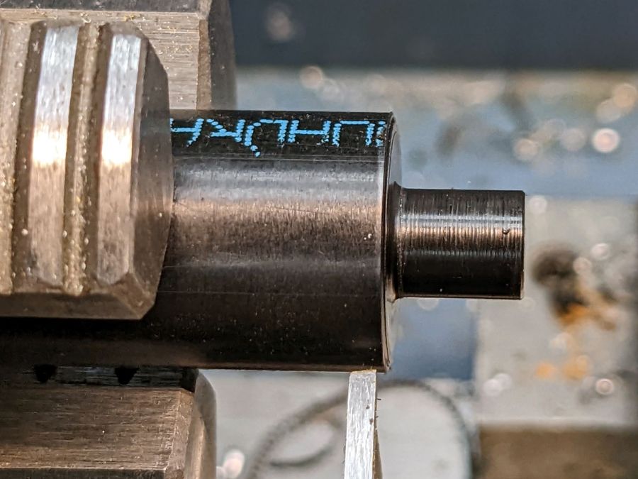
The M4 bolt clamping the holder to the main laser tube now goes through a Delrin bushing. I drilled out the original 4 mm screw hole to 6 mm to provide room for the bushing:
The bushing has a wide flange to soak up the excess space in the clamp ring:
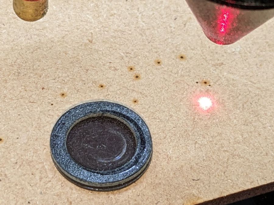
With all that in place, the dimmer dot is visually about 0.3 mm in diameter:
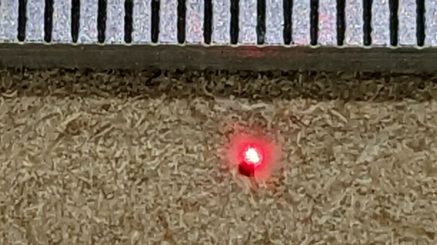
The crappy image quality comes from excessive digital zoom. The visible dot on the MDF surface is slightly larger than the blown-out white area in the image.
The CO₂ laser hole is offset from the red laser spot by about 0.3 mm in both X and Y. Eyeballometrically, the hole falls within the (dimmed) spot diameter, so this is as good as it gets. I have no idea how durable the alignment will be, but it feels sturdier than it started.
Because the red dot beam is 25° off vertical, every millimeter of vertical misalignment (due to non-flat surfaces, warping, whatever) shifts the red dot position half a millimeter in the XY plane. You can get a beam combiner to collimate the red dot with the main beam axis, but putting more optical elements in the beam path seems like a Bad Idea™ in general.
The OpenSCAD source code as a GitHub Gist:
| // Laser cutter red-dot module fine adjust | |
| // Ed Nisley KE4ZNU 2022-09-22 | |
| Layout = "Show"; // [Build, Show] | |
| /* [Hidden] */ | |
| ThreadThick = 0.25; | |
| ThreadWidth = 0.40; | |
| HoleWindage = 0.2; | |
| Protrusion = 0.1; // make holes end cleanly | |
| inch = 25.4; | |
| ID = 0; | |
| OD = 1; | |
| LENGTH = 2; | |
| function IntegerMultiple(Size,Unit) = Unit * ceil(Size / Unit); | |
| //———————- | |
| // Dimensions | |
| PointerOD = 8.0 + 0.2; // plus loose turning fit | |
| Aperture = 5.0; // clear space for lens | |
| SkewAngle = 2.5; | |
| MountRing = [10.0,16.0,8.0]; // OEM laser module holder | |
| GripRim = [Aperture,MountRing[OD] + 2*1.5,3.0]; // finger grip around OD | |
| NumSides = 24; | |
| //———————- | |
| // Useful routines | |
| module PolyCyl(Dia,Height,ForceSides=0) { // based on nophead's polyholes | |
| Sides = (ForceSides != 0) ? ForceSides : (ceil(Dia) + 2); | |
| FixDia = Dia / cos(180/Sides); | |
| cylinder(r=(FixDia + HoleWindage)/2, | |
| h=Height, | |
| $fn=Sides); | |
| } | |
| //———————- | |
| // Holder geometry | |
| module Holder() { | |
| difference() { | |
| union() { | |
| cylinder(d=GripRim[OD],h=GripRim[LENGTH],$fn=NumSides); | |
| PolyCyl(MountRing[ID],MountRing[LENGTH] + GripRim[LENGTH],NumSides); | |
| } | |
| translate([0,0,-Protrusion]) // close enough without skew angle | |
| PolyCyl(Aperture,2*MountRing[LENGTH],NumSides); | |
| translate([0,0,MountRing[LENGTH]/2 + GripRim[LENGTH]]) | |
| rotate([0,SkewAngle,0]) | |
| translate([0,0,-MountRing[LENGTH]/2]) | |
| PolyCyl(PointerOD,2*MountRing[LENGTH],NumSides); | |
| } | |
| } | |
| //———————- | |
| // Build it | |
| if (Layout == "Show") { | |
| Holder(); | |
| } | |
| if (Layout == "Build") { | |
| Holder(); | |
| } |

Comments
2 responses to “Laser Cutter: Improving the Red-Dot Pointer”
Can you elaborate little more on polarizer part?
I don’t understand 3 circle part.
Is is two filters and spacer?
Also source of filter.
Thank you.
The secret: diode lasers produce a kinda-sorta Gaussian beam that’s plane-polarized. Passing the beam through a crossed polarizing filter reduces the brightness, so you see only the brighter central part of the beam, which means reducing the brightness reduces the spot size on the target.
There are two parts to that filter: the polarizing film (one circle) and a ring of double-sided foam (two circles make a ring!) to stick it in place. The “three circles” was obscure when I re-read it, too, and I actually used only two circles: one to cut both outer perimeters and another to cut the inner perimeter of the tape.
The polarizing film came from a surplus find many many years ago, but if you have a battered pair of polarizing sunglasses in a drawer, you’ve got the raw material. Worst case, you can have a lifetime supply:
https://www.amazon.com/s?k=polarizing+film
https://www.ebay.com/sch/i.html?_nkw=polarizing%20film
Today I Learned: Gameboys need replacement polarizing filters! [grin]