The Smell of Molten Projects in the Morning

Ed Nisley's Blog: Shop notes, electronics, firmware, machinery, 3D printing, laser cuttery, and curiosities. Contents: 100% human thinking, 0% AI slop.

Tag: Sherline

Sherline CNC mill

  • Tour Easy 1 W Amber Running Light: Internal Plate

    Tour Easy 1 W Amber Running Light: Internal Plate

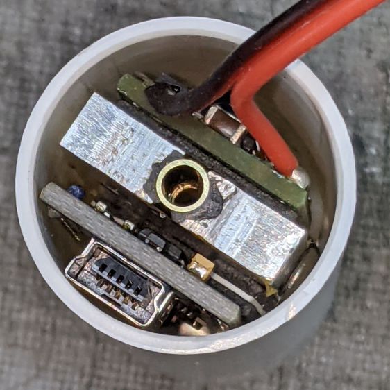
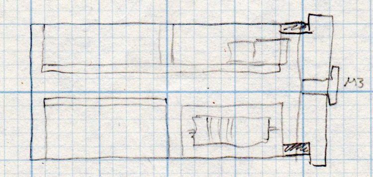
    A semi-scaled doodle laying out an Arduino Nano and the MP1584 regulator board suggested they might fit behind the heatsink with the 1 W LED:

    Amber running light - board layout doodle - side
    Amber running light – board layout doodle – side

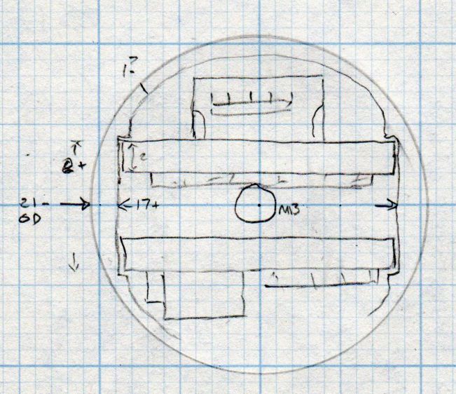
    A somewhat more detailed doodle of the end view prompted me to bore the PVC pipe out to 23 mm:

    Amber running light - board layout doodle - end
    Amber running light – board layout doodle – end

    The prospect of designing a 3D printed holder for the boards suggested Quality Shop Time combined with double-stick foam tape would ensure a better outcome.

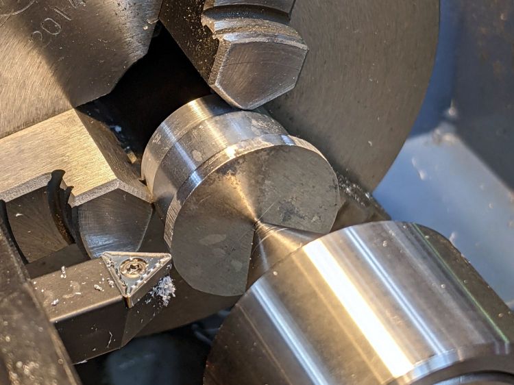
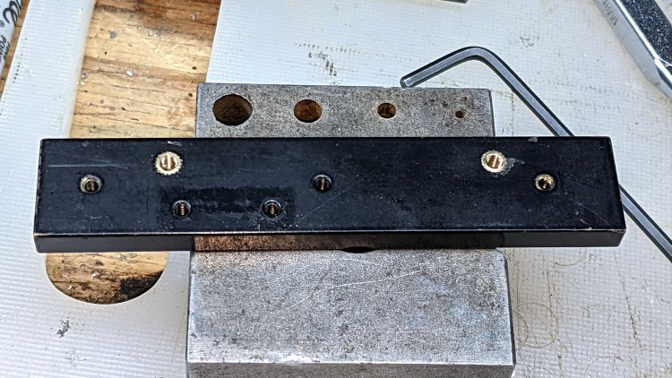
    So I bandsawed the remains of a chunky angle bracket into a pair of rectangles, flycut All The Sides to square them up, and tapped a pair of M3 holes along one edge of each:

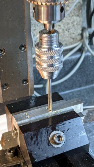
    1 W LED Running Light - baseplate tapping
    1 W LED Running Light – baseplate tapping

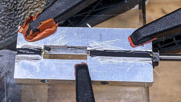
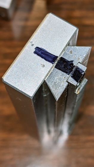
    The other long edges got the V groove that killed the Sherline’s Y axis nut:

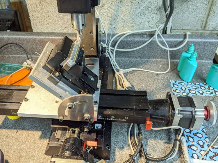
    Sherline Y-Axis Nut Mishap - setup
    Sherline Y-Axis Nut Mishap – setup

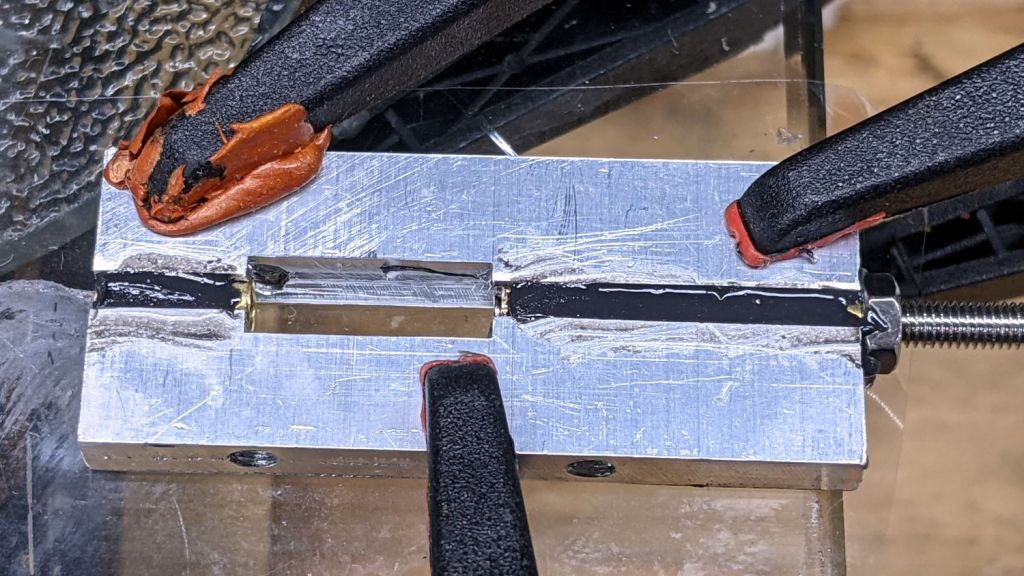
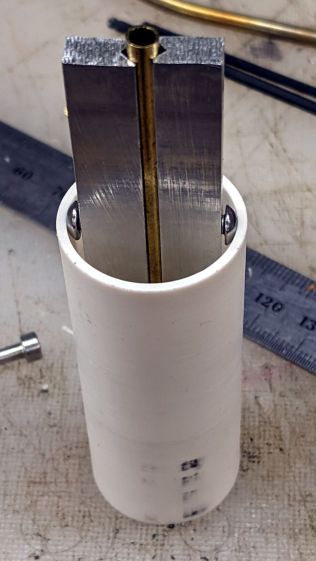
    The groove holds a length of 4 mm OD (actually 5/32 inch, but don’t tell anybody) brass tubing:

    1 W LED Running Light - baseplate trial fit
    1 W LED Running Light – baseplate trial fit

    The M3 button head screws are an admission of defeat, as I could see no way of controlling the width + thickness of the aluminum slabs to get a firm push fit in the PVC tube. The screws let me tune for best picture after everything else settled out.

    A little more machining opened up the top of the groove:

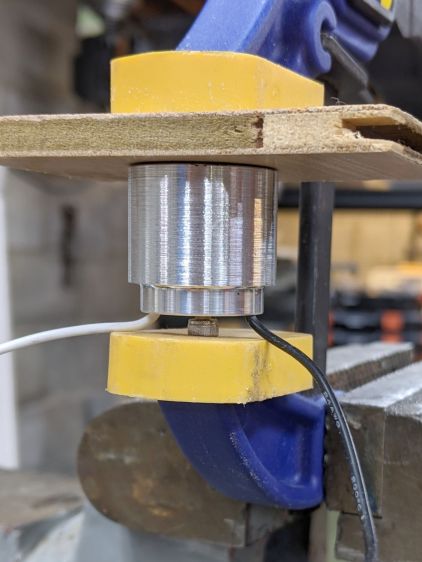
    1 W LED Running Light - baseplate dry assembly
    1 W LED Running Light – baseplate dry assembly

    A short M3 button head screw (with its head turned down to 4 mm) drops into the slot and holds the slab to the threaded hole in the LED heatsink. The long screw is holding the threaded insert in place for this dry fit.

    I doodled a single long screw through the whole thing, but having it fall off the heatsink when taking the rear cover off seemed like a Bad Idea™. An M3 button head screw uses a 2 mm hex key that fits neatly through the threaded insert, thereby making it work.

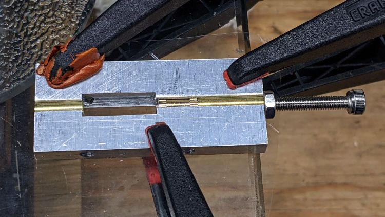
    Butter it up with epoxy, scrape off the excess, and let things cure:

    1 W LED Running Light - baseplate curing
    1 W LED Running Light – baseplate curing

    This was obviously made up as I went along …

  • Sherline CNC Mill: Y-Axis Nut Mishap

    Sherline CNC Mill: Y-Axis Nut Mishap

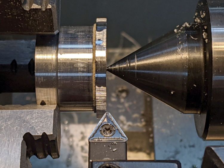
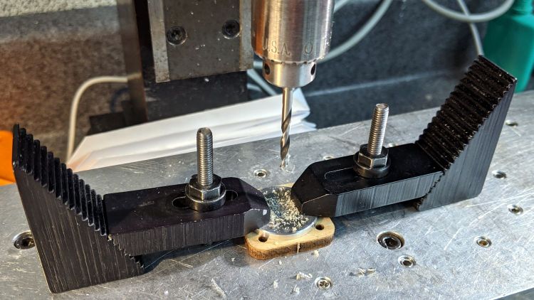
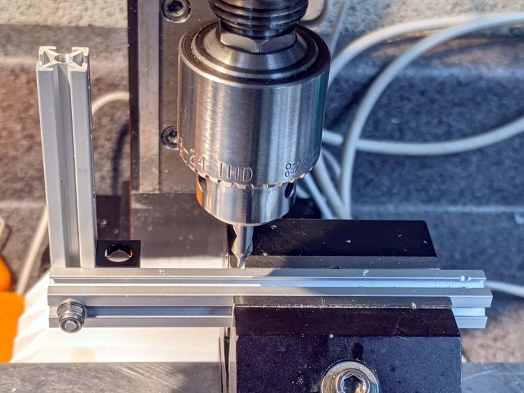
    The need to gnaw a V groove into the side of two 60 mm aluminum bars led to this Sherline CNC mill setup:

    Sherline Y-Axis Nut Mishap - setup
    Sherline Y-Axis Nut Mishap – setup

    Milling the near end of the bars put the angle plate’s rear lock screw within a millimeter of the column; the vise fits in exactly one spot on the angle plate and that’s where the jaws must be.

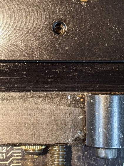
    While controlling the mill with the Joggy Thing and some manual command entry, because it’s easier than real CNC programming, I overshot the near end and rammed the column with enough enthusiasm to dislodge the Y-axis leadscrew nut. An interlude of utter confusion ended with the backlash preload nut firmly jammed against the leadscrew coupler on the other end of travel:

    Sherline Y-Axis Nut Mishap - stuck preload nut
    Sherline Y-Axis Nut Mishap – stuck preload nut

    The paper shreds show where the bellows formerly stuck on the Y axis stage.

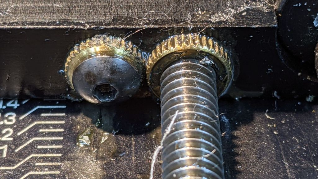
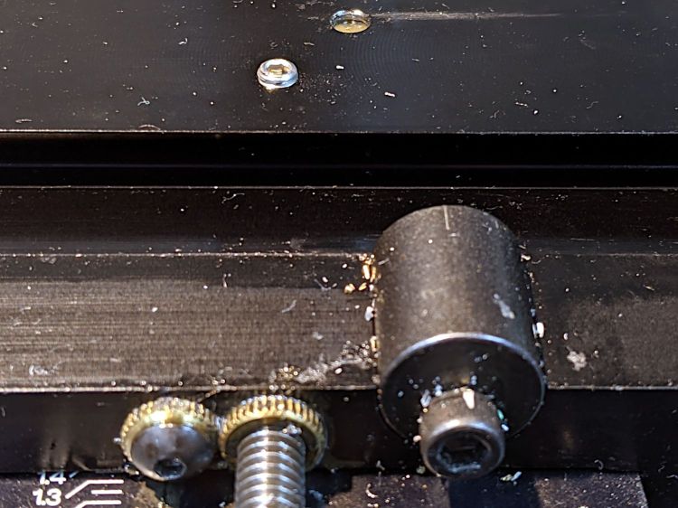
    The backlash nut chewed off a few star lock gear teeth on its way out, as seen here just above where they mesh:

    Sherline Y-Axis Nut Mishap - chewed star nut
    Sherline Y-Axis Nut Mishap – chewed star nut

    It’s been quite a few years since I took the thing apart to replace the nuts, so I used the opportunity to lube the otherwise inacessible X axis leadscrew inside its table upside down on the bench.

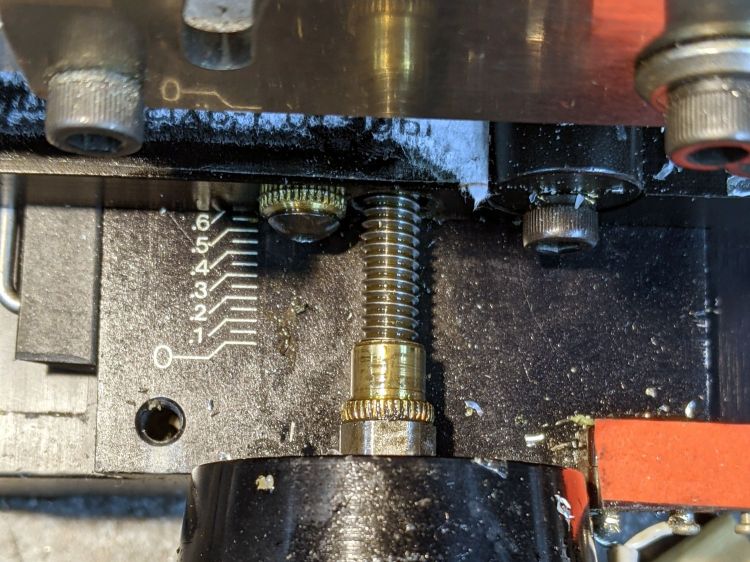
    The setscrew locking the Y axis leadscrew nut in place heaves into view with the X axis table off:

    Sherline Y-Axis Nut Mishap - setscrew
    Sherline Y-Axis Nut Mishap – setscrew

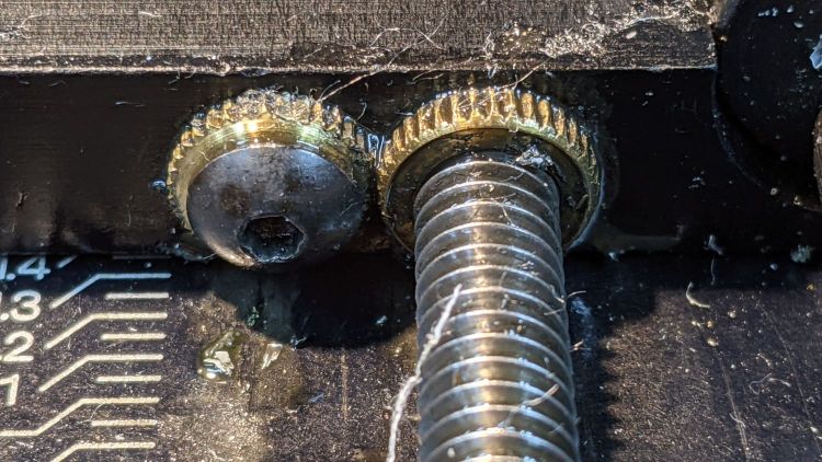
    I thought about jamming it in place with a second 10-32 setscrew, but the ones on hand were just an itsy too long and collided with the X-axis table:

    Sherline Y-Axis Nut Mishap - doubled setscrew
    Sherline Y-Axis Nut Mishap – doubled setscrew

    The thought of having the additional setscrew work loose, grind into the underside of the table, and require major surgery for recovery persuaded me to drop it back in the drawer.

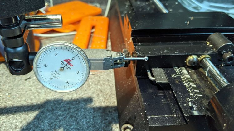
    With everything in place, I adjusted the backlash (on both axes) down to a few mils:

    Sherline Y-Axis Nut Mishap - backlash test
    Sherline Y-Axis Nut Mishap – backlash test

    Tweaking the X axis preload nut under the table is not my idea of a good time, but it’s been quite a while since I had to do that.

    Folding the new paper bellows and installing them took about as long as repairing the mill.

    Milling the second V groove worked fine; all is right with the Sherline again.

  • Running Light: 1 W LED Heatsink

    Running Light: 1 W LED Heatsink

    The general idea: a cylindrical holder / heatsink for a 1 W LED on the end of a tube clamped in a Tour Easy fairing mount, much like a flashlight.

    A pleasant evening at a virtual Squidwrench meeting produced the raw shape of the front end from a 1 inch aluminum rod:

    1 W LED Running Light - heatsink raw
    1 W LED Running Light – heatsink raw

    Trace the outline of the LED’s PCB inside the cylinder just for comfort, align to the center, and drill two holes with a little bit of clearance:

    1 W LED Running Light - heatsink drilling
    1 W LED Running Light – heatsink drilling

    For the 24 AWG silicone wire I used, a pair of 2 mm holes 8.75 mm out from the center suffice:

    1 W LED Running Light - heatsink fit
    1 W LED Running Light – heatsink fit

    Gnaw some wire clearance in the lens holder:

    1 W LED Running Light - wiring
    1 W LED Running Light – wiring

    Tap the central hole for an M3×0.5 screw, which may come in handy to pull the entire affair together.

    Epoxy the PCB onto the heatsink with the lens holder keeping it aligned in the middle:

    1 W LED Running Light - heatsink clamp
    1 W LED Running Light – heatsink clamp

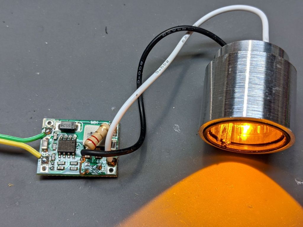
    Then see how hot it gets dissipating 900 mW with 360 mA of current from a 2.2 Ω resistor:

    1 W LED Running Light - heatsink test
    1 W LED Running Light – heatsink test

    As you might expect, it gets uncomfortably warm sitting on the bench, so it lacks surface area. The first pass will use a PVC cylinder for easy machining, but a full aluminum shell would eventually be a nice touch.

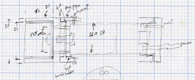
    A doodle with some dimensions and aspirational features:

    Running Light - 1 W LED case doodle
    Running Light – 1 W LED case doodle

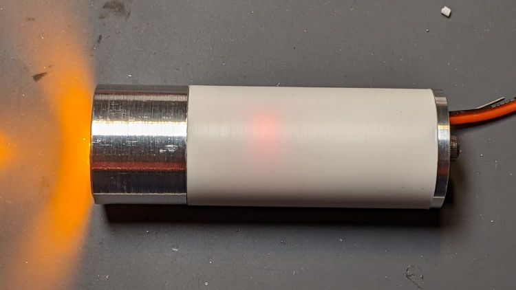
    Even without a lens and blinkiness, it’s attention-getting!

  • Microscope Stage Positioner: Rigid MakerBeam Edition

    Microscope Stage Positioner: Rigid MakerBeam Edition

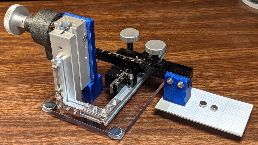
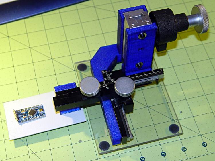
    Rebuilding the XYZ stage positioner with MakerBeam aluminum struts, but without the steel brackets, produce a much more rigid result:

    Microscope Stage Positioner - rigid Makerbeam
    Microscope Stage Positioner – rigid Makerbeam

    This requires drilling holes through the extrusions:

    Microscope Stage Positioner - Makerbeam drilling
    Microscope Stage Positioner – Makerbeam drilling

    Running the center drill down until it just nicks the sides produces enough of a pilot hole through the center section to capture the 3 mm drill. If I had to drill enough holes to make a fixture worthwhile, I could probably eliminate the divots.

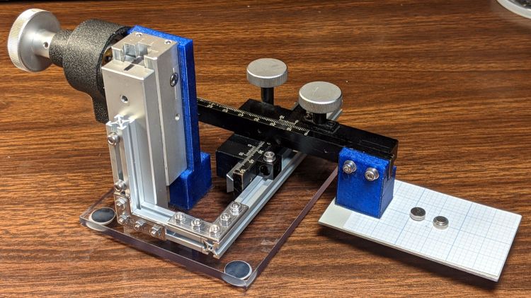
    Two more holes + epoxied M3 brass inserts attached the 60 mm beam directly to the Z Axis stage, thereby eliminating the vertical beam and a steel bracket:

    Microscope Stage Positioner - Makerbeam joints
    Microscope Stage Positioner – Makerbeam joints

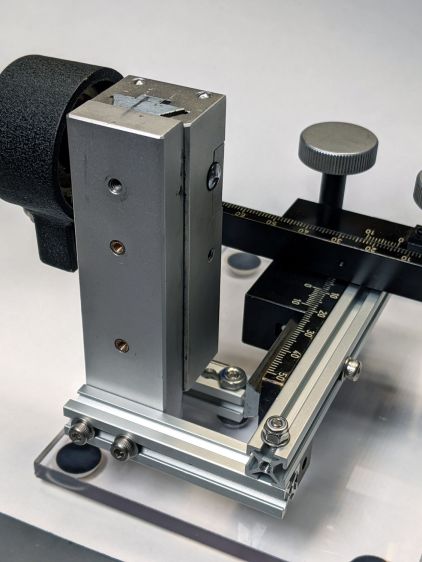
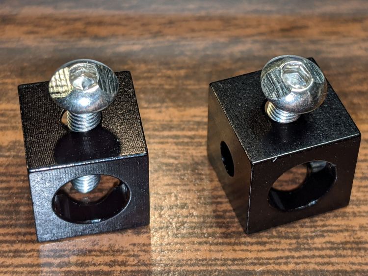
    The M3 SHCS attaching the 100 mm beam goes through both beams. I think you could get the same result with a Tee Nut or a 12 mm Square Head bolt, should you have those lying around and don’t want to drill another hole. The Corner Cube screwed into both beams prevents rotation and helps ensure perpendicularity.

    The Y stage now attaches directly to the beam, rather than through a pair of Corner Cubes, because I realized I wasn’t ever going to adjust its position.

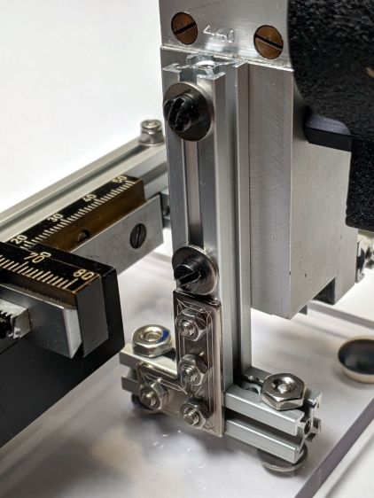
    The Z Axis stage stands on the plastic plate through a hellish mixture of metric and USA-ian screws. Basically, the 6-40 screws into the stage were long enough, the 6-32 screws through the plate fit the existing holes, and M3 screws are for MakerBeam:

    Microscope Stage Positioner - Z Axis base
    Microscope Stage Positioner – Z Axis base

    To my utter astonishment, the threads in the end of the vertical beam had the proper alignment to let a Square Head bolt snug the beam against the 40 mm beam on the plate. As a result, the L Bracket just prevents the vertical beam from turning on the screw and the combination is as rigid as you (well, I) could want.

    The 40 mm beam has two spurious holes, because I thought I could avoid drilling another hole in the baseplate. Nobody will ever notice.

    After squaring and tightening everything, the 100 mm beam along the Y Axis is now horizontal within 0.2 mm and the X Axis is horizontal to better than I can measure.

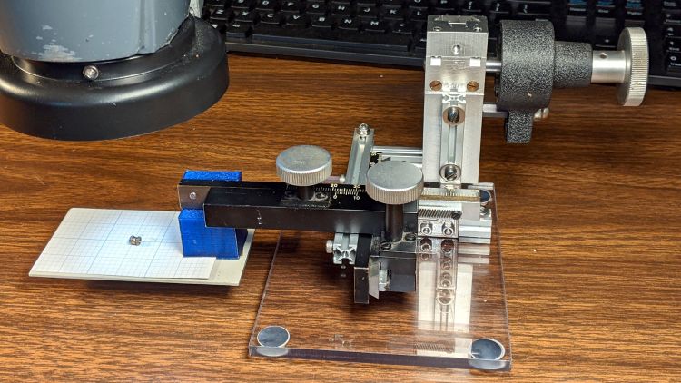
    It’s definitely Good Enough™ for me:

    Microscope Stage Positioner - in use
    Microscope Stage Positioner – in use

    Remember, nothing exceeds like excess …
  • Microscope Stage Positioner: MakerBeam Rebuild MVP

    Microscope Stage Positioner: MakerBeam Rebuild MVP

    Over the course of half a decade (!), the 3D printed arm on the XYZ positioner I use with the stereo zoom microscope sagged:

    Microscope Stage Positioner - PETG creep angle
    Microscope Stage Positioner – PETG creep angle

    It’s about what you’d expect from a plastic beam carrying a big lump of brass and steel:

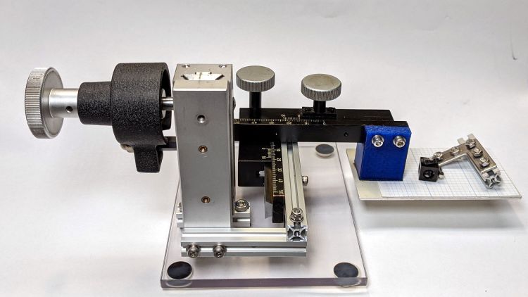
    Microscope Stage Positioner
    Microscope Stage Positioner

    The near side of that arm (the -Y end) drooped about 5 mm below than the side nearest the Z axis slide, so it was time for an update.

    Having some MakerBeam ready to hand, this didn’t take long:

    Microscope Stage Positioner - Makerbeam overview
    Microscope Stage Positioner – Makerbeam overview

    Protip: before dismantling a fitted slide, mark one end so you know how to put it back together. Bonus points for taking a picture:

    Microscope Stage Positioner - slide marking
    Microscope Stage Positioner – slide marking

    Double bonus points for writing a blog post.

    Rather than fight with the existing fine-pitch USA-ian screws, I drilled out their threaded holes:

    Microscope Stage Positioner - Y slide drilling
    Microscope Stage Positioner – Y slide drilling

    And epoxied 3 mm brass inserts in their place:

    Microscope Stage Positioner - Y slide M3 inserts
    Microscope Stage Positioner – Y slide M3 inserts

    Those holes match up with a pair of corner cubes normally appearing on the end of the beams:

    Microscope Stage Positioner - BHCS mods for Makerbeam
    Microscope Stage Positioner – BHCS mods for Makerbeam

    It turns out M3 button head cap screws will slide into the beams if you file the slightest angle on opposite sides of the button, although a small bag of tiny tee nuts should arrive in a while.

    Then a variety of brackets spliced everything together:

    Microscope Stage Positioner - Makerbeam detail
    Microscope Stage Positioner – Makerbeam detail

    Although it looks strictly from industrial, it actually wasn’t much better than the plastic edition and, in fact, the beam supporting the XY slides sagged about the same 5 mm. The plastic upright post also contributed a bit of wobble.

    It turns out that the extruded aluminum beams have plenty of longitudinal and torsional stiffness, but all those flat steel fittings don’t.

    There’s a way to work with the beam strengths, rather than against them, but that’s a story for another day …

  • Tek CC Milled Cursor: MVP

    Tek CC Milled Cursor: MVP

    What a difference 100 µm can make:

    Hairline V tool tests - 0.3 mm 10 kRPM 24 ipm
    Hairline V tool tests – 0.3 mm 10 kRPM 24 ipm

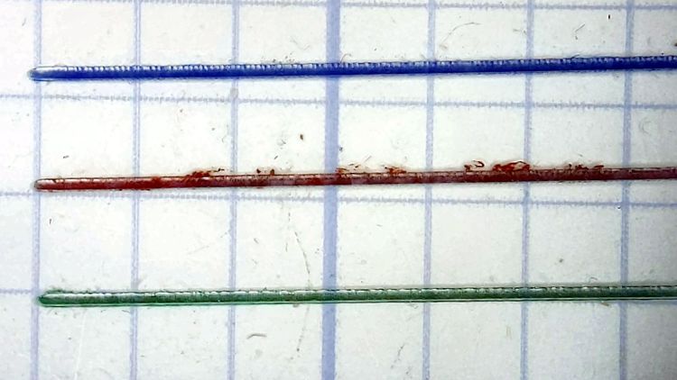
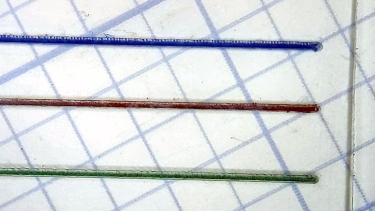
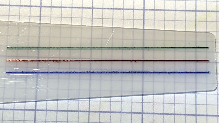
    All three hairlines have 0.3 mm depth of cut, with the spindle running at 10 kRPM and the cut proceeding at 24 inch/min = 600 mm/min. All three cuts went through a strip of water + detergent along their length, which seems to work perfectly.

    The cuts start on the left side:

    Hairline V tool tests - 0.3 mm 10 kRPM 24 ipm - start
    Hairline V tool tests – 0.3 mm 10 kRPM 24 ipm – start

    I cut the red hairline through the PET cursor’s protective film to confirm doing it that way is a Bad Idea™; the gnarly appearance is sufficient proof.

    The cuts end on the right:

    Hairline V tool tests - 0.3 mm 10 kRPM 24 ipm - end
    Hairline V tool tests – 0.3 mm 10 kRPM 24 ipm – end

    Eyeballometrically, the cuts are the same depth on both ends, with a slight texture difference at the start as the X axis ramps up to full speed.

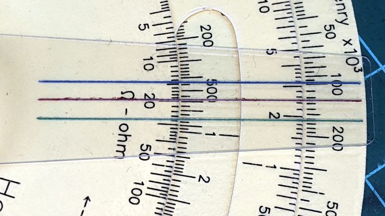
    They’d be a bit stout on an old-school engraved slide rule, but look just fine laid against a laser-printed Homage Tek Circuit Computer:

    Hairline V tool tests - 0.3 mm 10 kRPM 24 ipm - Tek CC
    Hairline V tool tests – 0.3 mm 10 kRPM 24 ipm – Tek CC

    Flushed with success, here’s a fresh-cut red hairline in action:

    Tek CC cursor hairline - V tool red fill
    Tek CC cursor hairline – V tool red fill

    The end of the cursor sticks out 1 mm over the rim of the bottom deck, because I wanted to find out whether that would make it easier to move. It turns out the good folks at Tek knew what they were doing; a too-long cursor buckles too easily.

    The trick will be touching off the V tool accurately enough on the cursor surface to get the correct depth of cut. The classic machinist’s technique involves a pack of rolling papers, which might be coming back into fashion here in NY.

  • Sherline Tooling Plate Re-Alignment

    Sherline Tooling Plate Re-Alignment

    Engraving a 0.2 mm deep hairline in a Tek Circuit Computer cursor showed the fixture had a bit of a tilt:

    Hairline V tool - 0.2 0.3 0.4 DOC 10K RPM - water cool mid
    Hairline V tool – 0.2 0.3 0.4 DOC 10K RPM – water cool mid

    The bottom blue hairline started with a good cut and ended with the V tool skating along the surface without cutting. The raggedy red one just above it is what happens when you (well, I) try engraving a hairline through Kapton tape without coolant; just don’t do that thing.

    The 3D printed fixture holding the cursor came from a neurotically aligned Makergear M2 and the tooling plate has never had much attention to its alignment, so I figured the tilt probably came from crud between the tooling plate and the Sherline’s X axis table, with the printed fixture contributing zilch to the problem.

    Which turned out to be the case. Scraping a few flakes from the bottom of the plate and top of the table, dissolving old crud with water + alcohol, and passing a file over both surfaces definitely made a difference. I converted a sheet of 0.1 mm laminating plastic film into a pad by punching holes for the T-nuts:

    Sherline tooling plate pad
    Sherline tooling plate pad

    Snugging the tooling plate down produced perfect alignment along the length of three 0.3 mm deep hairlines:

    Hairline V tool tests - 0.3 mm 10 kRPM 24 ipm
    Hairline V tool tests – 0.3 mm 10 kRPM 24 ipm

    That was surprisingly easy …