Collecting the battery dimensions into a table should make it easier to generate new holders for astable multivibrators:
//- Battery dimensions - rationalized from several samples
//  Coordinate origin at battery end with contacts, key openings downward

T_NAME = 0;
T_SIZE = 1;
T_CONTACTS = 2;
T_KEYS = 3;

BatteryData = [
  ["NP-BX1",[43.0,30.0,9.5],[[-0.75,6.0,6.2],[-0.75,16.0,6.2]],[[1.70,3.70,2.90],[1.70,3.60,2.90]]],
  ["NB-5L", [45.0,32.0,8.0],[[-0.82,4.5,3.5],[-0.82,11.0,3.5]],[[2.2,0.75,2.0],[2.2,2.8,2.0]]],
  ["NB-6L",[42.5,35.5,7.0],[[-0.85,5.50,3.05],[-0.85,11.90,3.05]],[[2.0,0.70,2.8],[2.0,2.00,2.8]]],
];

echo(str("Battery: ",BatteryName));

BatteryIndex = search([BatteryName],BatteryData,1,0)[0];
echo(str(" Index: ",BatteryIndex));

BatterySize = BatteryData[BatteryIndex][T_SIZE];          // X = length, Y = width, Z = thickness
echo(str(" Size: ",BatterySize));

Contacts = BatteryData[BatteryIndex][T_CONTACTS];         // relative to battery edge, front, and bottom
echo(str(" Contacts: ",Contacts));

ContactOC = Contacts[1].y - Contacts[0].y;                // + and - terminals for pogo pin contacts
ContactCenter = Contacts[0].y + ContactOC/2;

KeyBlocks = BatteryData[BatteryIndex][T_KEYS];            // recesses in battery face set X position
echo(str(" Keys: ",KeyBlocks));
A new boolean, RGBCircuit, adds a second pair of wire strut bases and punches holes in them:
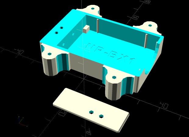
Which looks about like you’d expect in real life:
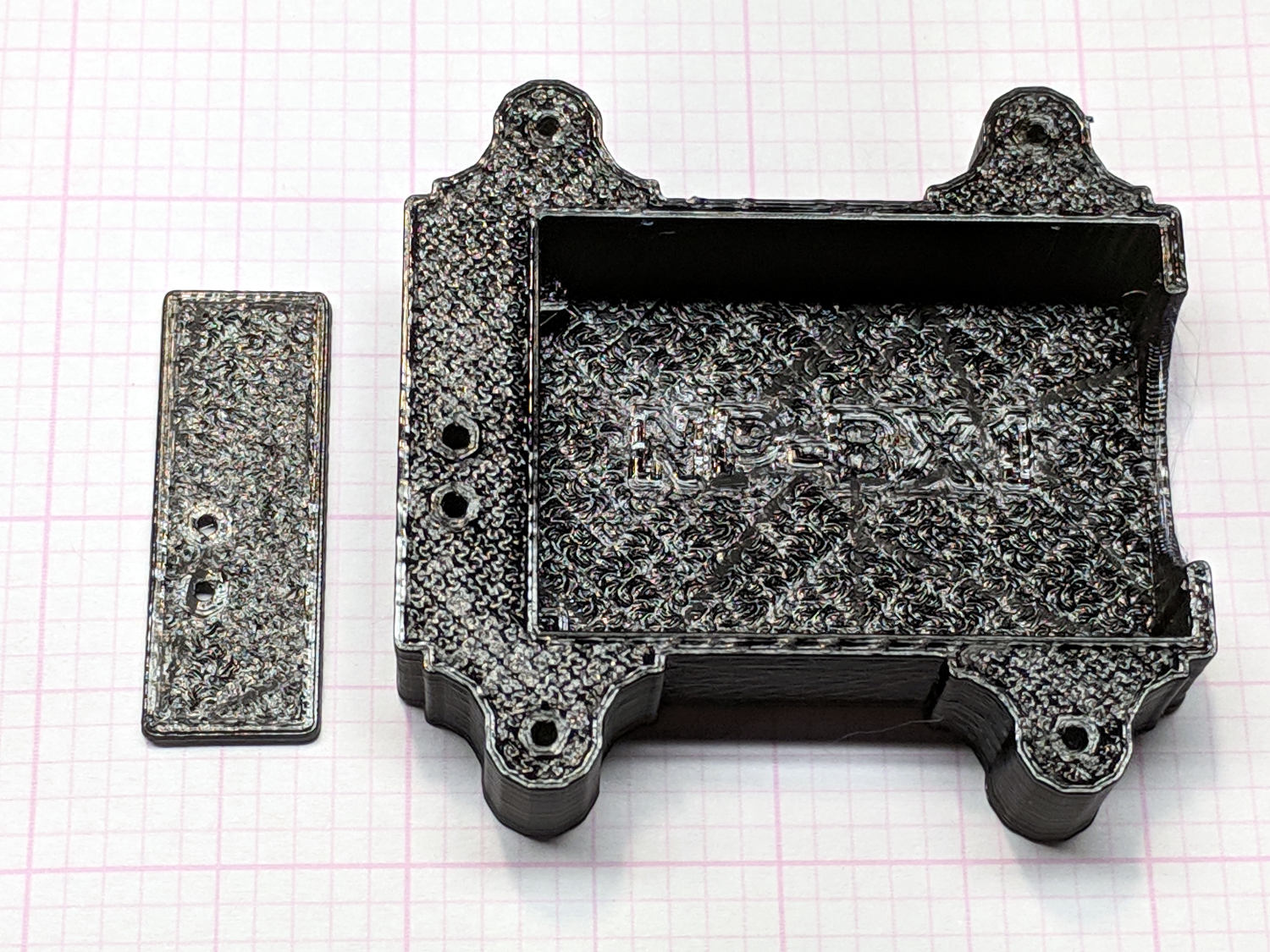
The lettering, of course, doesn’t come through clearly, but it suffices as a hint for which battery to use.
The four vertical struts will support three astable multivibrators, each driving one color of a common-anode RGB LED. It remains to be seen if there’s enough room for all the parts along the sides of the battery pack.
The OpenSCAD source code as a GitHub Gist:
This file contains hidden or bidirectional Unicode text that may be interpreted or compiled differently than what appears below. To review, open the file in an editor that reveals hidden Unicode characters.
Learn more about bidirectional Unicode characters
| // Holder for Li-Ion battery packs | |
| // Ed Nisley KE4ZNU January 2013 | |
| // 2018-11-15 Adapted for 1.5 mm pogo pins, battery data table | |
| /* [Layout options] */ | |
| BatteryName = "NP-BX1"; // [NP-BX1,NB-5L,NB-6L] | |
| RGBCircuit = true; // false = 1 strut pair, true = 2 pairs | |
| Layout = "Show"; // [Build,Show,Fit,Case,Lid,Pins] | |
| /* [Extrusion parameters] – must match reality! */ | |
| // Print with +2 shells and 3 solid layers | |
| ThreadThick = 0.25; | |
| ThreadWidth = 0.40; | |
| HoleWindage = 0.2; | |
| function IntegerMultiple(Size,Unit) = Unit * ceil(Size / Unit); | |
| Protrusion = 0.1; // make holes end cleanly | |
| /* [Hidden] */ | |
| inch = 25.4; | |
| BuildOffset = 3.0; // clearance for build layout | |
| Gap = 2.0; // separation for Fit parts | |
| //- Basic dimensions | |
| WallThick = 4*ThreadWidth; // holder sidewalls | |
| BaseThick = 6*ThreadThick; // bottom of holder to bottom of battery | |
| TopThick = 6*ThreadThick; // top of battery to top of holder | |
| //- Battery dimensions – rationalized from several samples | |
| // Coordinate origin at battery end with contacts, key openings downward | |
| T_NAME = 0; | |
| T_SIZE = 1; | |
| T_CONTACTS = 2; | |
| T_KEYS = 3; | |
| BatteryData = [ | |
| ["NP-BX1",[43.0,30.0,9.5],[[-0.75,6.0,6.2],[-0.75,16.0,6.2]],[[1.70,3.70,2.90],[1.70,3.60,2.90]]], | |
| ["NB-5L", [45.0,32.0,8.0],[[-0.82,4.5,3.5],[-0.82,11.0,3.5]],[[2.2,0.75,2.0],[2.2,2.8,2.0]]], | |
| ["NB-6L",[42.5,35.5,7.0],[[-0.85,5.50,3.05],[-0.85,11.90,3.05]],[[2.0,0.70,2.8],[2.0,2.00,2.8]]], | |
| ]; | |
| echo(str("Battery: ",BatteryName)); | |
| BatteryIndex = search([BatteryName],BatteryData,1,0)[0]; | |
| echo(str(" Index: ",BatteryIndex)); | |
| BatterySize = BatteryData[BatteryIndex][T_SIZE]; // X = length, Y = width, Z = thickness | |
| echo(str(" Size: ",BatterySize)); | |
| Contacts = BatteryData[BatteryIndex][T_CONTACTS]; // relative to battery edge, front, and bottom | |
| echo(str(" Contacts: ",Contacts)); | |
| ContactOC = Contacts[1].y – Contacts[0].y; // + and – terminals for pogo pin contacts | |
| ContactCenter = Contacts[0].y + ContactOC/2; | |
| KeyBlocks = BatteryData[BatteryIndex][T_KEYS]; // recesses in battery face set X position | |
| echo(str(" Keys: ",KeyBlocks)); | |
| //- Pin dimensions | |
| ID = 0; | |
| OD = 1; | |
| LENGTH = 2; | |
| PinShank = [1.5,2.0,6.5]; // shank, flange, compressed length | |
| PinFlange = [1.5,2.0,0.5]; // flange, length included in PinShank | |
| PinTip = [0.9,0.9,2.5]; // extended spring-loaded tip | |
| WireOD = 1.7; // wiring from pins to circuitry | |
| PinChannel = WireOD; // cut behind flange for solder overflow | |
| PinRecess = 3.0; // recess behind pin flange end for epoxy fill | |
| echo(str("Contact tip dia: ",PinTip[OD])); | |
| echo(str(" .. shank dia: ",PinShank[ID])); | |
| OverTravel = 0.5; // space beyond battery face at X origin | |
| //- Holder dimensions | |
| GuideRadius = ThreadWidth; // friction fit ridges | |
| GuideOffset = 7; // from compartment corners | |
| LidOverhang = 2.0; // atop of battery for retention | |
| LidClearance = LidOverhang * (BatterySize.z/BatterySize.x); // … clearance above battery for tilting | |
| echo(str("Lid clearance: ",LidClearance)); | |
| CaseSize = [BatterySize.x + PinShank[LENGTH] + OverTravel + PinRecess + GuideRadius + WallThick, | |
| BatterySize.y + 2*WallThick + 2*GuideRadius, | |
| BatterySize.z + BaseThick + TopThick + LidClearance]; | |
| echo(str("Case size: ",CaseSize)); | |
| CaseOffset = [-(PinShank[LENGTH] + OverTravel + PinRecess),-(WallThick + GuideRadius),0]; // position around battery | |
| ThumbRadius = 10.0; // thumb opening at end of battery | |
| CornerRadius = 3*ThreadThick; // nice corner rounding | |
| LidSize = [-CaseOffset.x + LidOverhang,CaseSize.y,TopThick]; | |
| LidOffset = [0.0,CaseOffset.y,0]; | |
| //- Wire struts | |
| StrutDia = 1.6; // AWG 14 = 1.6 mm | |
| StrutSides = 3*4; | |
| StrutBase = [StrutDia,StrutDia + 4*WallThick,CaseSize.z – TopThick]; // ID = wire, OD = buildable | |
| StrutOC = IntegerMultiple(CaseSize.y + StrutBase[OD],5.0); // set easy OC wire spacing | |
| echo(str("Strut OC: ",StrutOC)); | |
| //———————- | |
| // Useful routines | |
| module PolyCyl(Dia,Height,ForceSides=0) { // based on nophead's polyholes | |
| Sides = (ForceSides != 0) ? ForceSides : (ceil(Dia) + 2); | |
| FixDia = Dia / cos(180/Sides); | |
| cylinder(r=(FixDia + HoleWindage)/2,h=Height,$fn=Sides); | |
| } | |
| //——————- | |
| //– Guides for tighter friction fit | |
| module Guides() { | |
| translate([GuideOffset,-GuideRadius,0]) | |
| PolyCyl(2*GuideRadius,(BatterySize.z – Protrusion),4); | |
| translate([GuideOffset,(BatterySize.y + GuideRadius),0]) | |
| PolyCyl(2*GuideRadius,(BatterySize.z – Protrusion),4); | |
| translate([(BatterySize.x – GuideOffset),-GuideRadius,0]) | |
| PolyCyl(2*GuideRadius,(BatterySize.z – Protrusion),4); | |
| translate([(BatterySize.x – GuideOffset),(BatterySize.y + GuideRadius),0]) | |
| PolyCyl(2*GuideRadius,(BatterySize.z – Protrusion),4); | |
| translate([(BatterySize.x + GuideRadius),GuideOffset/2,0]) | |
| PolyCyl(2*GuideRadius,(BatterySize.z – Protrusion),4); | |
| translate([(BatterySize.x + GuideRadius),(BatterySize.y – GuideOffset/2),0]) | |
| PolyCyl(2*GuideRadius,(BatterySize.z – Protrusion),4); | |
| } | |
| //– Contact pins | |
| // Rotated to put them in their natural oriention | |
| // Aligned to put tip base / end of shank at Overtravel limit | |
| module PinShape() { | |
| translate([-(PinShank[LENGTH] + OverTravel),0,0]) | |
| rotate([0,90,0]) | |
| rotate(180/6) | |
| union() { | |
| PolyCyl(PinTip[OD],PinShank[LENGTH] + PinTip[LENGTH],6); | |
| PolyCyl(PinShank[ID],PinShank[LENGTH] + Protrusion,6); // slight extension for clean cuts | |
| PolyCyl(PinFlange[OD],PinFlange[LENGTH],6); | |
| } | |
| } | |
| // Position pins to put end of shank at battery face | |
| // Does not include recess access into case | |
| module PinAssembly() { | |
| union() { | |
| for (p = Contacts) | |
| translate([0,p.y,p.z]) | |
| PinShape(); | |
| translate([-(PinShank[LENGTH] + OverTravel) + PinChannel/2, // solder space | |
| ContactCenter, | |
| Contacts[0].z]) | |
| cube([PinChannel, | |
| (Contacts[1].y – Contacts[0].y + PinFlange[OD]), | |
| PinFlange[OD]],center=true); | |
| for (j=[-1,1]) // wire channels | |
| translate([-(PinShank[LENGTH] + OverTravel – PinChannel/2), | |
| j*ContactOC/4 + ContactCenter, | |
| Contacts[0].z – PinFlange[OD]/2]) | |
| rotate(180/6) | |
| PolyCyl(WireOD,CaseSize.z,6); | |
| } | |
| } | |
| //– Case with origin at battery corner | |
| module Case() { | |
| difference() { | |
| union() { | |
| difference() { | |
| union() { | |
| translate([(CaseSize.x/2 + CaseOffset.x), // basic case shape | |
| (CaseSize.y/2 + CaseOffset.y), | |
| (CaseSize.z/2 – BaseThick)]) | |
| hull() | |
| for (i=[-1,1], j=[-1,1], k=[-1,1]) | |
| translate([i*(CaseSize.x/2 – CornerRadius), | |
| j*(CaseSize.y/2 – CornerRadius), | |
| k*(CaseSize.z/2 – CornerRadius)]) | |
| sphere(r=CornerRadius/cos(180/8),$fn=8); // cos() fixes undersize spheres! | |
| for (i=[0,RGBCircuit ? 1 : 0]) { // add strut bases | |
| hull() | |
| for (j=[-1,1]) | |
| translate([i*(BatterySize.x – StrutBase[OD]),j*StrutOC/2 + BatterySize.y/2,-BaseThick]) | |
| rotate(180/StrutSides) | |
| cylinder(d=StrutBase[OD],h=StrutBase[LENGTH],$fn=StrutSides); | |
| translate([i*(BatterySize.x – StrutBase[OD]),BatterySize.y/2,StrutBase[LENGTH]/2 – BaseThick]) | |
| cube([2*StrutBase[OD],StrutOC,StrutBase[LENGTH]],center=true); | |
| } | |
| } | |
| translate([-OverTravel,-GuideRadius,0]) | |
| cube([(BatterySize.x + GuideRadius + OverTravel), | |
| (BatterySize.y + 2*GuideRadius), | |
| (BatterySize.z + LidClearance + Protrusion)]); // battery space | |
| } | |
| Guides(); // improve friction fit | |
| translate([-OverTravel,-GuideRadius,0]) // battery keying blocks | |
| cube(KeyBlocks[0] + [OverTravel,GuideRadius,0],center=false); | |
| translate([-OverTravel,(BatterySize.y – KeyBlocks[1].y),0]) | |
| cube(KeyBlocks[1] + [OverTravel,GuideRadius,0],center=false); | |
| } | |
| translate([2*CaseOffset.x, // battery top access | |
| (CaseOffset.y – Protrusion), | |
| BatterySize.z + LidClearance]) | |
| cube([2*CaseSize.x,(CaseSize.y + 2*Protrusion),2*TopThick]); | |
| for (i2=[0,RGBCircuit ? 1 : 0]) { // strut wire holes and fairing | |
| for (j=[-1,1]) | |
| translate([i2*(BatterySize.x – StrutBase[OD]),j*StrutOC/2 + BatterySize.y/2,0]) | |
| PolyCyl(StrutBase[ID],StrutBase[LENGTH],6); | |
| for (i=[-1,1], j=[-1,1]) | |
| translate([i*StrutBase[OD] + (i2*(BatterySize.x – StrutBase[OD])), | |
| j*StrutOC/2 + BatterySize.y/2, | |
| -(BaseThick + Protrusion)]) | |
| rotate(180/StrutSides) | |
| PolyCyl(StrutBase[OD],StrutBase[LENGTH] + 2*Protrusion,StrutSides); | |
| } | |
| translate([(BatterySize.x – Protrusion), // remove thumb notch | |
| (CaseSize.y/2 + CaseOffset.y), | |
| (ThumbRadius)]) | |
| rotate([90,0,0]) | |
| rotate([0,90,0]) | |
| cylinder(r=ThumbRadius, | |
| h=(WallThick + GuideRadius + 2*Protrusion), | |
| $fn=22); | |
| PinAssembly(); // pins and wiring | |
| translate([CaseOffset.x + PinRecess + Protrusion,(Contacts[1].y + Contacts[0].y)/2,Contacts[0].z]) | |
| translate([-PinRecess,0,0]) | |
| cube([2*PinRecess, | |
| (Contacts[1].y – Contacts[0].y + PinFlange[OD]/cos(180/6) + 2*HoleWindage), | |
| 2*PinFlange[OD]],center=true); // pin insertion hole | |
| LineSpace = 7.0; | |
| translate([BatterySize.x/2,CaseSize.y/2,-ThreadThick]) | |
| linear_extrude(height=2*ThreadThick,convexity=10) | |
| text(text=BatteryName,size=5,spacing=1.20,font="Arial:style:Bold",halign="center",valign="center"); | |
| translate([BatterySize.x/2,CaseSize.y/2,-(BaseThick + Protrusion)]) | |
| linear_extrude(height=ThreadThick + Protrusion,convexity=10) | |
| mirror([0,1,0]) | |
| text(text="KE4ZNU",size=6,spacing=1.20,font="Arial:style:Bold",halign="center",valign="center"); | |
| } | |
| } | |
| // Lid position offset to match case | |
| module Lid() { | |
| difference() { | |
| translate([-LidSize.x/2 + LidOffset.x + LidOverhang,LidSize.y/2 + LidOffset.y,0]) | |
| difference() { | |
| hull() | |
| for (i=[-1,1], j=[-1,1], k=[-1,1]) | |
| translate([i*(LidSize.x/2 – CornerRadius), | |
| j*(LidSize.y/2 – CornerRadius), | |
| k*(LidSize.z – CornerRadius)]) // double thickness for flat bottom | |
| sphere(r=CornerRadius,$fn=8); | |
| translate([0,0,-LidSize.z/2]) // remove bottom | |
| cube([(LidSize.x + 2*Protrusion),(LidSize.y + 2*Protrusion),LidSize.z],center=true); | |
| translate([LidSize.x/8,0,0]) | |
| cube([LidSize.x/4,0.75*LidSize.y,4*ThreadThick],center=true); // epoxy recess | |
| } | |
| translate([0,0,-(Contacts[0].z + PinFlange[OD])]) // punch wire holes | |
| PinAssembly(); | |
| } | |
| } | |
| //——————- | |
| // Build it! | |
| if (Layout == "Case") | |
| Case(); | |
| if (Layout == "Lid") | |
| Lid(); | |
| if (Layout == "Pins") { | |
| color("Silver",0.5) | |
| PinShape(); | |
| PinAssembly(); | |
| } | |
| if (Layout == "Show") { // reveal pin assembly | |
| difference() { | |
| Case(); | |
| translate([(CaseOffset.x – Protrusion), | |
| Contacts[1].y, | |
| Contacts[1].z]) | |
| cube([(-CaseOffset.x + Protrusion), | |
| CaseSize.y, | |
| (CaseSize.z – Contacts[0].z + Protrusion)]); | |
| translate([(CaseOffset.x – Protrusion), | |
| (CaseOffset.y – Protrusion), | |
| 0]) | |
| cube([(-CaseOffset.x + Protrusion), | |
| Contacts[0].y + Protrusion – CaseOffset.y, | |
| CaseSize.z]); | |
| } | |
| translate([0,0,BatterySize.z + Gap]) | |
| Lid(); | |
| color("Silver",0.15) | |
| PinAssembly(); | |
| } | |
| if (Layout == "Build") { | |
| translate([-(CaseSize.x/2 + CaseOffset.x),-(CaseOffset.y – BuildOffset),BaseThick]) | |
| Case(); | |
| translate([CaseSize.x/2,-LidSize.x,0]) | |
| rotate(90) | |
| Lid(); | |
| } | |
| if (Layout == "Fit") { | |
| Case(); | |
| translate([0,0,(BatterySize.z + Gap)]) | |
| Lid(); | |
| color("Silver",0.25) | |
| PinAssembly(); | |
| } | |

Comments
One response to “Astable Multivibrator: Battery Base for RGB LED”
[…] cannot (or, perhaps, should not attempt to) solder parts to 14 AWG wires seated in a 3D printed battery holder base, so I cleaned up the edges of two polycarbonate […]