The Smell of Molten Projects in the Morning

Ed Nisley's Blog: Shop notes, electronics, firmware, machinery, 3D printing, laser cuttery, and curiosities. Contents: 100% human thinking, 0% AI slop.

Tag: Sherline

Sherline CNC mill

  • 123 Block Links: Cap Screw Head Pins

    123 Block Links: Cap Screw Head Pins

    Contemplating a project using a small saw in the Sherline suggested that attaching the workpiece to the side of a 123 block would simplify the machining. My blocks have a centered quintet of 3/8-16 tapped holes through the 2×3 side, all the remaining holes are untapped, and it has no smaller holes. The hole spacing doesn’t match the Sherline tooling plate, but the T-nut slots in the underlying table would suffice.

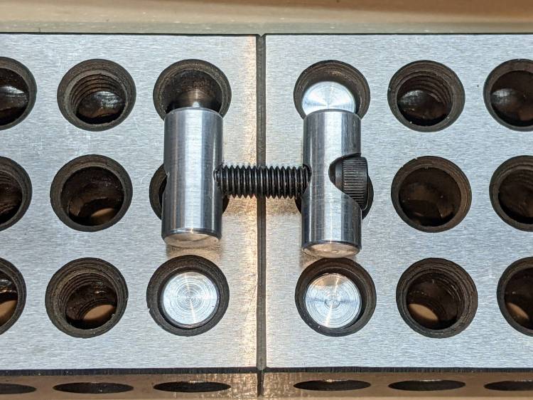
    Rather than run long 10-32 screws through the entire block, It Would Be Nice to use short screws from, say, the nearest holes:

    123 Block Links - assembled
    123 Block Links – assembled

    I cannot possibly be the first person to have this idea, but the obvious keywords don’t produce any useful results on The Intertubes, other than a link to a different (and far more complex) block with counterbored holes of various sizes.

    Update: Jason found a video about building those blocks and somebody else built some pins similar to mine. Nope, I’m definitely not the first person to have this idea!

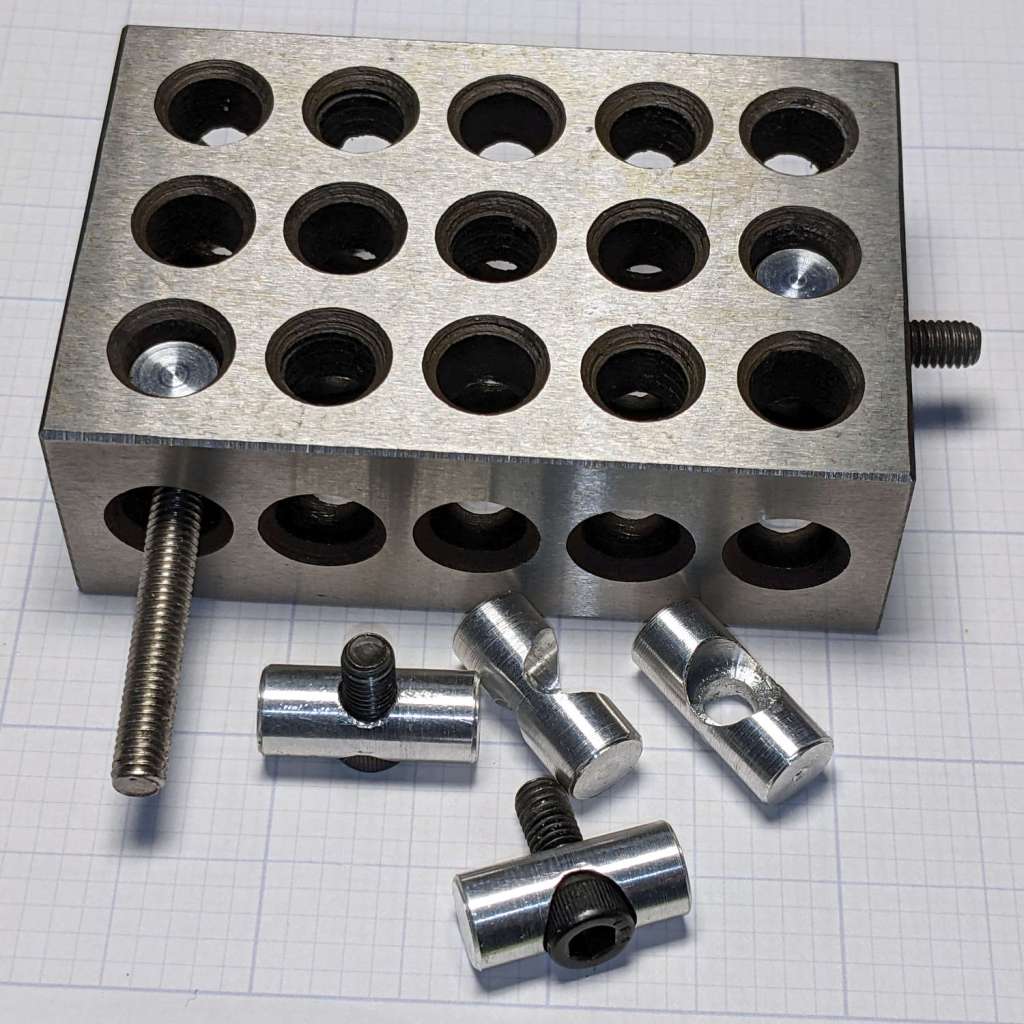
    Further doodling produced some useful dimensions:

    123 Block Links - SHCS head pin doodle
    123 Block Links – SHCS head pin doodle

    The holes through the blocks probably came from a 5/16 inch drill, the 75% thread depth diameter for the 3/8-16 taps used on the threaded holes. They’re distorted, full of debris, and hardened enough to kill a file, so I eventually settled on 8.2 mm pins that pass through most of the holes.

    The socket head screws seat at the pin axis, because the pin diameter is scary close to the counterbore diameter and I didn’t see much point in finesse. I started with a half-inch aluminum rod and peeled it to size, because it simplified the clamping and I have a bunch of them.

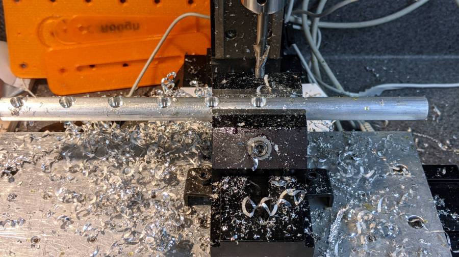
    The pins are 3/4 inch long to leave a little space on either side of the 1 inch deep holes. I started with comfort marks along the length of the rod:

    123 Block Links - laser alignment
    123 Block Links – laser alignment

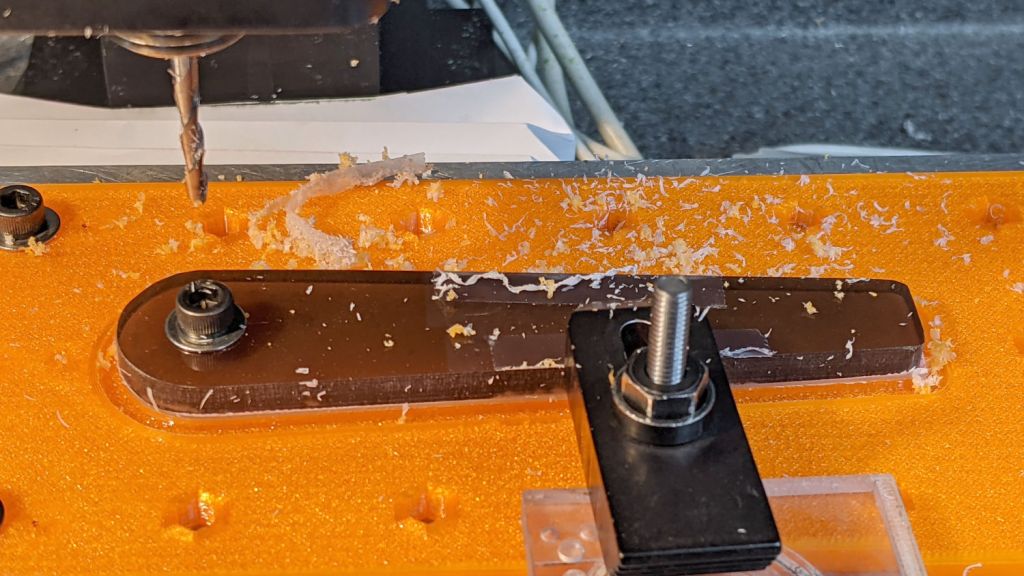
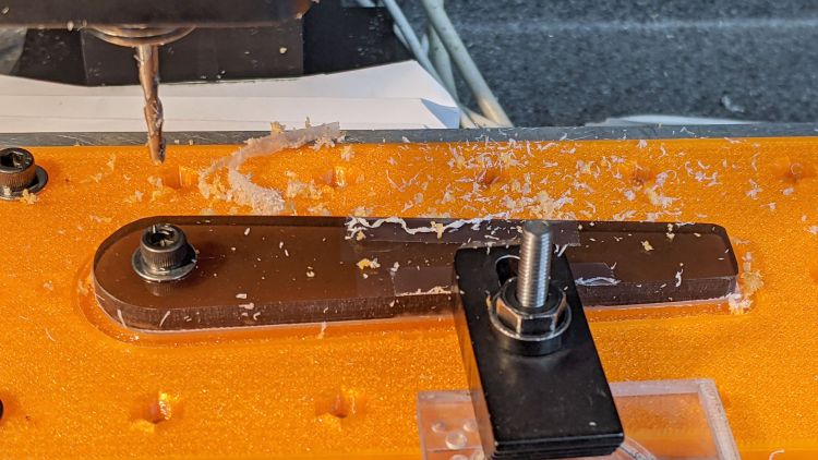
    Center-drill so the clearance drill doesn’t skitter off the top:

    123 Block Links - center drilling
    123 Block Links – center drilling

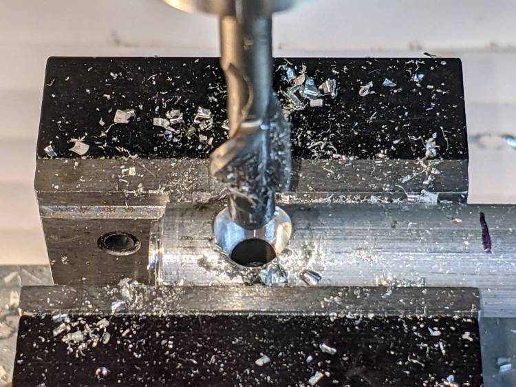
    The counterbore calls for a 0.204 inch = #6 drill, just slightly larger than the #7 clearance drill for a 10-32 screw:

    123 Block Links - counterbore
    123 Block Links – counterbore

    I touched off the counterbore flutes on the sides of the hole, then drilled downward half the 12.8 mm actual rod diameter:

    123 Block Links - 10-32 SHCS test fit
    123 Block Links – 10-32 SHCS test fit

    Lower the counterbore into the hole again, relax the vise enough to let the rod slide, jog the spindle to X = -25.4 mm, and tighten the vise again:

    123 Block Links - index setup
    123 Block Links – index setup

    I figured I needed four pins, tops, so make half a dozen to be sure:

    123 Block Links - all c-bored
    123 Block Links – all c-bored

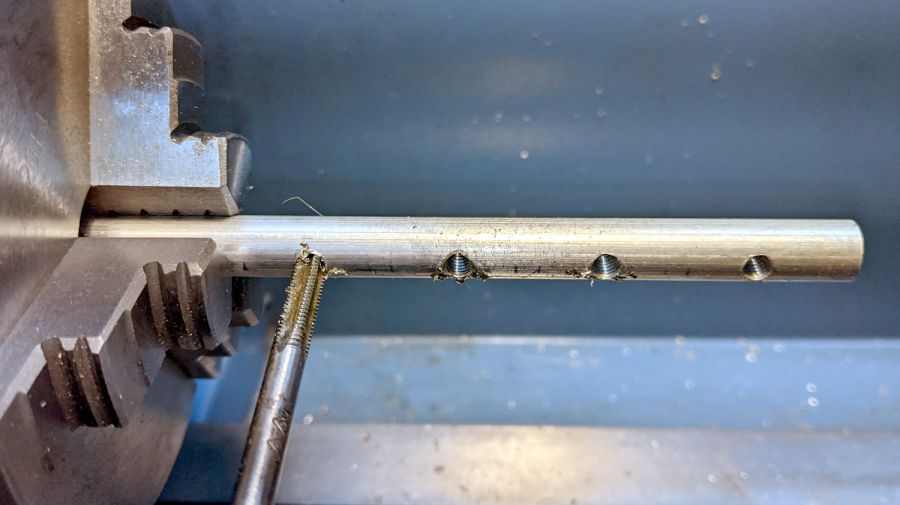
    Stick the rod in the mini-lathe chuck, add some comfort marks, and prepare to peel it down to 8.2 mm:

    123 Block Links - lathe setup
    123 Block Links – lathe setup

    Having done the lathe work during a Squidwrench remote meeting, I have no pictures of the process, but it goes a little something like this:

    • Peel off 0.5 mm at a time, stopping just beyond the mark on the left
    • Mark 3/8 inch on each side of the hole center
    • Face the end
    • Chamfer the rim with a file
    • Clean up the body hole and counterbore
    • Part the pin off a bit to the left of the mark
    • Remove the rod
    • Chuck the pin with the cut off end outward
    • Face to the mark
    • Chamfer
    • Repeat for all six pins
    • Done!

    It’s tedious, but not particularly difficult.

    Futher doodling suggested the need for threaded pins to join two blocks together.

  • Tek Circuit Computer: Cursor Hairline

    Tek Circuit Computer: Cursor Hairline

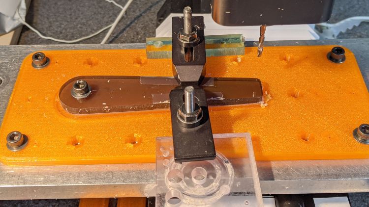
    Given a machined cursor blank, clamp it into position:

    Tek CC Cursor - cursor hairline fixture
    Tek CC Cursor – cursor hairline fixture

    You don’t want to clamp the cursor directly to the Sherline tooling plate, because the diamond drag bit would pass over two or three of those 10-32 screw holes which would, by the conservation of perversity, leave visible defects. In hindsight, I should have put a recess for an aluminum plate in there.

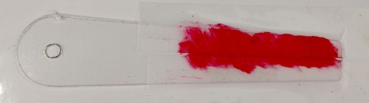
    After a single pass at Z=-4.0 mm, add two strips of tape to protect the adjoining surface and scribble it with red lacquer crayon:

    Tek CC Cursor - tape color fill
    Tek CC Cursor – tape color fill

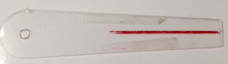
    Peel the tape off:

    Tek CC Cursor - tape removed
    Tek CC Cursor – tape removed

    Then wipe off the residue using a soft cloth wetted with denatured alcohol:

    Tek CC Cursor - red cursor detail
    Tek CC Cursor – red cursor detail

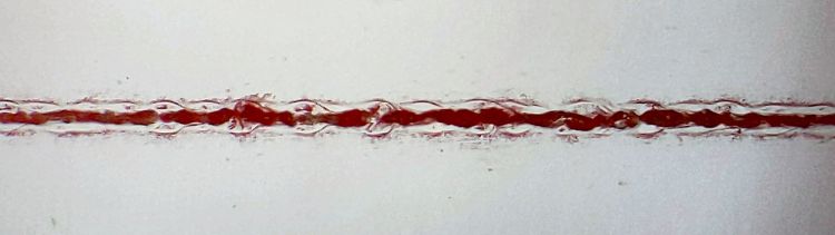
    That looks much like the previous efforts. I’d like a more uniform trench, but I don’t know how to get there from here.

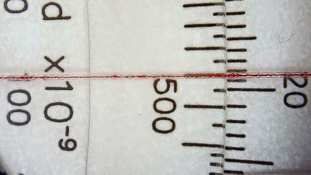
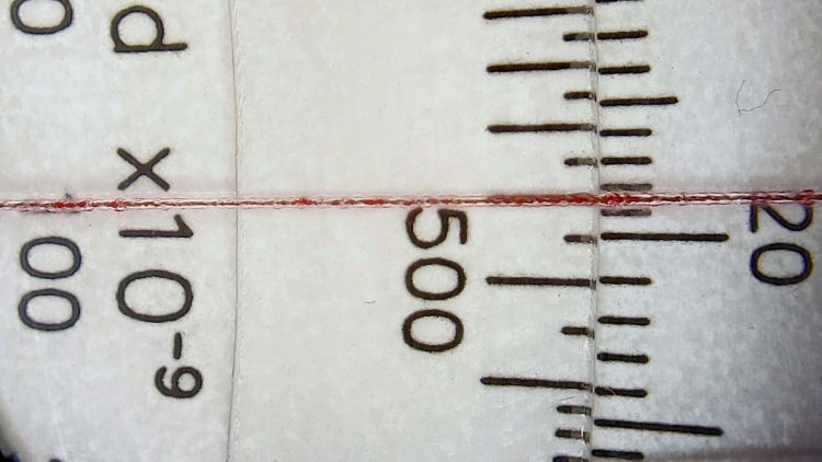
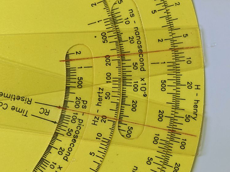
    In any event, the hairline looks pretty good against laser-printed scales:

    Tek CC Cursor - red cursor white laser decks - magnified
    Tek CC Cursor – red cursor white laser decks – magnified

    The new cursor is the lower one lying atop a laser-printed Pickett-style Circuit Computer:

    Tek CC Cursor - red cursor yellow laser decks - overview
    Tek CC Cursor – red cursor yellow laser decks – overview

    Looks good enough to eat, as the saying goes …

  • Tek Circuit Computer: Cursor Milling Toolpath

    Tek Circuit Computer: Cursor Milling Toolpath

    Unlike the adhesive fixture, this setup requires a pause while milling the cursor outline to reclamp it from the front:

    Tek CC Cursor Fixture - outline rear clamp
    Tek CC Cursor Fixture – outline rear clamp

    The trick is applying the front clamp before releasing the rear clamp:

    Tek CC Cursor Fixture - outline both clamp
    Tek CC Cursor Fixture – outline both clamp

    Then continue the mission:

    Tek CC Cursor Fixture - outline front clamp
    Tek CC Cursor Fixture – outline front clamp

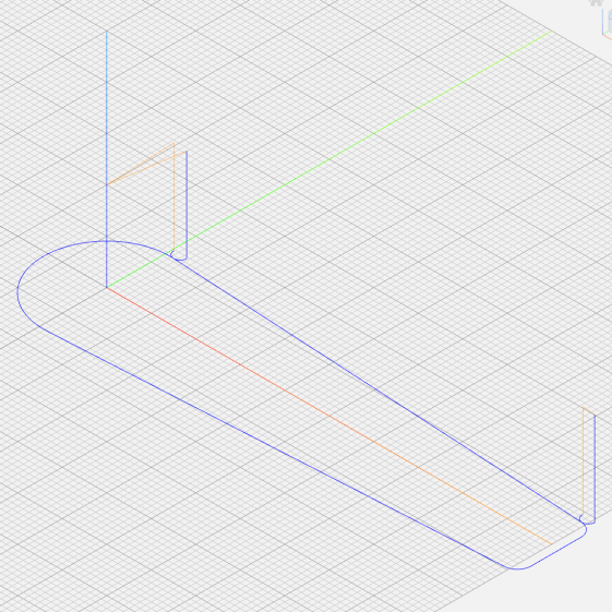
    Because the tool path includes cutter compensation, GCMC adds entry and exit arcs to ensure a smooth transition:

    Tek CC Cursor - Milling path
    Tek CC Cursor – Milling path

    The pix show a single cursor in the fixture while verifying the setup worked the way it should. Obviously, milling a stack of cursors eliminates a whole bunch of fiddling.

    The tweaked MillCursor function from the mostly otherwise unchanged GCMC code:

        comment("Clamp on rear half of cursor!");
    
        local cp = {p0};                                             // enter at hub tangent point
        cp += varc_ccw([0mm,-2*p0.y,-],-hr,0,0.2mm,5deg) + p0;       // arc to tangent at hub bottom
    
        cp += {[p1.x,-p1.y,-]};                                      // lower tip entry point
        cp += varc_ccw([p2.x-p1.x,-(p2.y-p1.y),-],CursorTipRadius,0,0.2mm,5deg) + [p1.x,-p1.y,-];  // arc to tip exit at p2
    
        cp += varc_ccw([p1.x-p2.x,p1.y-p2.y,-],CursorTipRadius,0,0.2mm,5deg) + p2;  // arc to tip exit at p1
    
        goto([-,-,CursorSafeZ]);
        goto([0,0,-]);
        feedrate(MillSpeed);
        tracepath_comp(cp,CutterOD/2,TPC_OLDZ + TPC_RIGHT + TPC_ARCIN + TPC_ARCOUT);
    
        comment("Clamp on front half of cursor!");
        pause();                                      // wait for reclamping
    
        p1.z = MillZ;                                //  ... set milling depth
        cp = {p1};
        cp += {p0};
                                                     // exit at hub tangent
        tracepath_comp(cp,CutterOD/2,TPC_OLDZ + TPC_RIGHT + TPC_ARCIN + TPC_ARCOUT);
    
    <<< snippage >>>
    
      goto([-,-,CursorSafeZ]);
      goto([0,0,-]);
    

    Next, scribing a nice hairline with the new fixture.

  • Tek Circuit Computer: 3D Printed Cursor Milling Fixture

    Tek Circuit Computer: 3D Printed Cursor Milling Fixture

    The original Tektronix Circuit Computer cursor was probably die-cut from a larger sheet carrying pre-printed hairlines:

    Tek CC - genuine - detail
    Tek CC – genuine – detail

    Machining a punch-and-die setup lies well beyond my capabilities, particularly given the ahem anticipated volume, so milling seems the only practical way to produce a few cursors.

    Attaching a cursor blank to a fixture with sticky tape showed that the general idea worked reasonably well:

    Tek CC - Cursor blank on fixture
    Tek CC – Cursor blank on fixture

    However, the tape didn’t have quite enough griptivity to hold the edges completely flat against milling forces (a downcut bit might have worked better) and I found myself chasing the cutter with a screwdriver to hold the cursor in place. Worse, the tape’s powerful attraction to swarf made it a single-use item.

    Some tinkering showed a single screw in the (pre-drilled) pivot hole, without adhesive underneath, lacked enough oomph to keep the far end of the cursor in place, which meant I had to think about how to hold it down with real clamps.

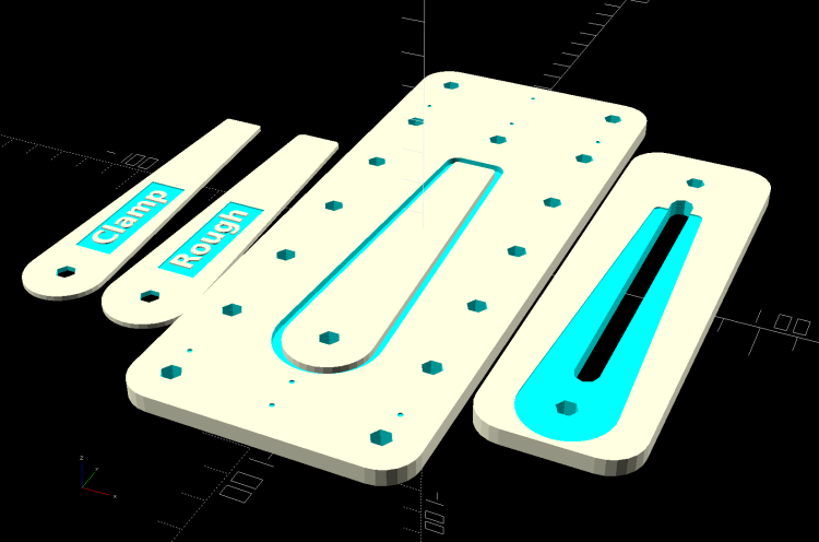
    Which, of course, meant conjuring a fixture from the vasty digital deep. The solid model includes the baseplate, two cutting templates, and a clamping fixture for engraving the cursor hairline:

    Cursor Fixture - build layout
    Cursor Fixture – build layout

    The perimeter of the Clamp template on the far left is 0.5 mm inside the cursor perimeter. Needing only one Clamp, I could trace it on a piece of acrylic, bandsaw it pretty close, introduce it to Mr Belt Sander for final shaping, and finally drill the hole:

    Tek CC Cursor Fixture - clamp drilling
    Tek CC Cursor Fixture – clamp drilling

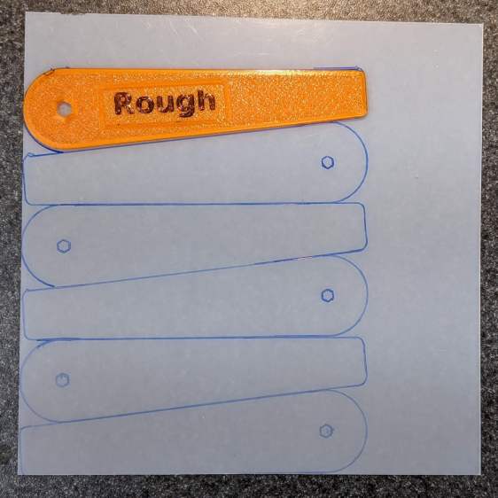
    The Rough template is 1.0 mm outside the cursor perimeter, so I can trace those outlines on a PET sheet:

    Tek CC Cursor Fixture - Rough template layout
    Tek CC Cursor Fixture – Rough template layout

    Then cut the patterns with a scissors, stack ’em up, and tape the edges to keep them aligned:

    TekCC Cursor Fixture - Rough template
    TekCC Cursor Fixture – Rough template

    Align the stack by feel, apply the Clamp to hold them in place, and secure the stack with a Sherline clamp:

    Tek CC Cursor Fixture - outline rear clamp
    Tek CC Cursor Fixture – outline rear clamp

    The alert reader will note it’s no longer possible to machine the entire perimeter in one pass; more on that in a while.

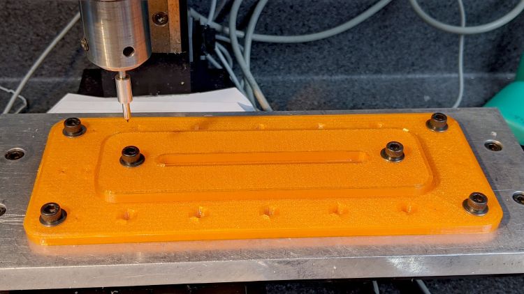
    The baseplate pretty much fills the entire Sherline tooling plate. It sports several alignment pips at known offsets from the origin at the center of the pivot hole:

    Tek CC Cursor Fixture - touch-off point
    Tek CC Cursor Fixture – touch-off point

    Dropping the laser alignment dot into a convenient pip, then touching off X and Y to the known offset sets the origin without measuring anything. Four screws in the corners align the plate well enough to not worry about angular tweakage.

    The OpenSCAD source code as a GitHub Gist:

    // Machining fixtures for Tek Circuit Computer cursor
    // Ed Nisley KE4ZNU Jan 2021
    Layout = "Show"; // [Show, Build, Cursor, Clamp, Rough, Engrave]
    /* [Hidden] */
    ThreadThick = 0.25;
    ThreadWidth = 0.40;
    HoleWindage = 0.2;
    Protrusion = 0.1; // make holes end cleanly
    inch = 25.4;
    function IntegerMultiple(Size,Unit) = Unit * ceil(Size / Unit);
    module PolyCyl(Dia,Height,ForceSides=0) { // based on nophead's polyholes
    Sides = (ForceSides != 0) ? ForceSides : (ceil(Dia) + 2);
    FixDia = Dia / cos(180/Sides);
    cylinder(d=(FixDia + HoleWindage),h=Height,$fn=Sides);
    }
    //———————-
    // Dimensions
    CursorHubOD = 1.0*inch; // original Tek CC was hard inch!
    CursorTipWidth = (9.0/16.0)*inch;
    CursorTipRadius = (1.0/16.0)*inch;
    CursorThick = 0.5; // plastic sheet thickness
    CutterOD = 3.175; // milling cutter dia
    CutterDepth = 2.0; // … depth of cut
    CutterLip = 0.5; // … clearance under edge
    ScribeOD = 3.0; // diamond scribe shank
    StudOC = [1.16*inch,1.16*inch]; // Sherline tooling plate grid
    StudClear = 5.0; // … screw clearance
    StudWasher = 11.0; // … washer OD
    CursorOffset = [-2*StudOC.x,0,0]; // hub center relative to fixture center
    // must have even multiples of stud spacing to put studs along centerlines
    BasePlateStuds = [6*StudOC.x,2*StudOC.y]; // fixture screws
    echo(str("Stud spacing: ",StudOC));
    CornerRad = 10.0; // corner radius
    BasePlate = [2*StudWasher + BasePlateStuds.x,2*StudWasher + BasePlateStuds.y,5.0];
    echo(str("Base Plate: ",BasePlate));
    EngravePlate = [5*StudOC.x,1.5*StudOC.y,BasePlate.z];
    echo(str("Engrave Plate: ",EngravePlate));
    TemplateThick = 6*ThreadThick;
    LegendThick = 2*ThreadThick;
    Gap = 3.0;
    //———————-
    // Import SVG of cursor outline
    // Requires our hub OD to match reality
    // Hub center at origin
    module CursorSVG(t=CursorThick,od=0) {
    hr = CursorHubOD/2;
    translate([-hr,-hr,0])
    linear_extrude(height=t,convexity=3)
    offset(r=od/2)
    import(file="/mnt/bulkdata/Project Files/Tektronix Circuit Computer/Firmware/TekCC-Cursor-Mark.svg",center=false);
    }
    //———————-
    // Milling fixture for cursor blanks
    module Fixture() {
    difference() {
    hull() // basic plate shape
    for (i=[-1,1], j=[-1,1])
    translate([i*(BasePlate.x/2 – CornerRad),j*(BasePlate.y/2 – CornerRad),0])
    cylinder(r=CornerRad,h=BasePlate.z,$fn=24);
    translate(CursorOffset + [0,0,BasePlate.z – CutterDepth])
    difference() {
    CursorSVG(CutterDepth + Protrusion,1.5*CutterOD);
    CursorSVG(CutterDepth + Protrusion,-CutterLip);
    }
    translate(CursorOffset + [0,0,BasePlate.z – 2*ThreadThick]) { // alignment pips
    for (x=[-20.0,130.0], y=[-30.0,0.0,30.0])
    translate([x,y,0])
    cylinder(d=4*ThreadWidth,h=1,$fn=6);
    for (x=[-30.0,130.0,150.0])
    translate([x,0,0])
    cylinder(d=4*ThreadWidth,h=1,$fn=6);
    }
    for (i=[-1,1], j=[-1,1]) // mounting stud holes
    translate([i*BasePlateStuds.x/2,j*BasePlateStuds.y/2,-Protrusion])
    rotate(180/6)
    PolyCyl(StudClear,BasePlate.z + 2*Protrusion,6);
    translate(CursorOffset + [0,0,-Protrusion]) // hub clamp hole
    rotate(180/6)
    PolyCyl(StudClear,BasePlate.z + 2*Protrusion,6);
    translate([2*StudOC.x,0,-Protrusion]) // tip clamp hole
    rotate(180/6)
    PolyCyl(StudClear,BasePlate.z + 2*Protrusion,6);
    for (i=[-2:2], j=[-1,1]) // side clamp holes
    translate([i*StudOC.x,j*StudOC.y,-Protrusion])
    rotate(180/6)
    PolyCyl(StudClear,BasePlate.z + 2*Protrusion,6);
    }
    }
    //———————-
    // Show-n-Tell cursor
    module Cursor() {
    difference() {
    CursorSVG(CursorThick,0.0);
    translate([0,0,-Protrusion])
    rotate(180/6)
    PolyCyl(StudClear,TemplateThick + 2*Protrusion,6);
    }
    }
    //———————-
    // Template for rough-cutting blanks
    module Rough() {
    bb = [40,12,LegendThick];
    difference() {
    CursorSVG(TemplateThick,1.0);
    translate([0,0,-Protrusion])
    rotate(180/6)
    PolyCyl(StudClear,TemplateThick + 2*Protrusion,6);
    difference() {
    translate([bb.x/2 + CursorHubOD/2,0,TemplateThick – bb.z/2 + Protrusion])
    cube(bb + [0,0,Protrusion],center=true);
    translate([bb.x/2 + CursorHubOD/2,0,TemplateThick – bb.z])
    linear_extrude(height=bb.z,convexity=10)
    text(text="Rough",size=7,spacing=1.00,font="DejaVu Sans:style:Bold",halign="center",valign="center");
    }
    }
    }
    //———————-
    // Template for aluminium clamping plate
    module Clamp() {
    bb = [40,12,LegendThick];
    difference() {
    CursorSVG(TemplateThick,-1.0);
    translate([0,0,-Protrusion])
    rotate(180/6)
    PolyCyl(StudClear,TemplateThick + 2*Protrusion,6);
    difference() {
    translate([bb.x/2 + CursorHubOD/2,0,TemplateThick – bb.z/2 + Protrusion])
    cube(bb + [0,0,Protrusion],center=true);
    translate([bb.x/2 + CursorHubOD/2,0,TemplateThick – bb.z])
    linear_extrude(height=bb.z,convexity=10)
    text(text="Clamp",size=7,spacing=1.00,font="DejaVu Sans:style:Bold",halign="center",valign="center");
    }
    }
    }
    //———————-
    // Engraving clamp
    module Engrave() {
    difference() {
    hull() // clamp outline
    for (i=[-1,1], j=[-1,1])
    translate([i*(EngravePlate.x/2 – CornerRad),j*(EngravePlate.y/2 – CornerRad),0])
    cylinder(r=CornerRad,h=EngravePlate.z,$fn=24);
    translate(CursorOffset + [0,0,-Protrusion])
    CursorSVG(CursorThick + Protrusion,0.5); // pocket for blank cursor
    translate(CursorOffset + [0,0,-Protrusion])
    rotate(180/6)
    PolyCyl(StudClear,EngravePlate.z + 2*Protrusion,6);
    translate([2*StudOC.x,0,-Protrusion])
    rotate(180/6)
    PolyCyl(StudClear,EngravePlate.z + 2*Protrusion,6);
    hull() {
    for (i=[-1,1])
    translate([i*1.5*StudOC.x,0,-Protrusion])
    PolyCyl(2*ScribeOD,EngravePlate.z + 2*Protrusion,8);
    }
    }
    }
    //———————-
    // Build it
    if (Layout == "Cursor") {
    Cursor();
    }
    if (Layout == "Clamp") {
    Clamp();
    }
    if (Layout == "Rough") {
    Rough();
    }
    if (Layout == "Engrave") {
    Engrave();
    }
    if (Layout == "Show") {
    Fixture();
    color("Green",0.3)
    translate(CursorOffset + [0,0,BasePlate.z + Protrusion])
    Cursor();
    color("Orange")
    translate(CursorOffset + [0,0,BasePlate.z + 10])
    Rough();
    color("Brown")
    translate(CursorOffset + [0,0,BasePlate.z + 20])
    Clamp();
    color("Gold")
    translate(0*CursorOffset + [0,0,BasePlate.z + 40])
    Engrave();
    }
    if (Layout == "Build"){
    rotate(90) {
    Fixture();
    translate([0,-((BasePlate.y + EngravePlate.y)/2 + Gap),EngravePlate.z])
    rotate([180,0,0])
    Engrave();
    translate(CursorOffset + [0,(BasePlate.y + CursorHubOD)/2 + Gap,0])
    Rough();
    translate(CursorOffset + [0,(BasePlate.y + 3*CursorHubOD)/2 + 2*Gap,0])
    Clamp();
    }
    }

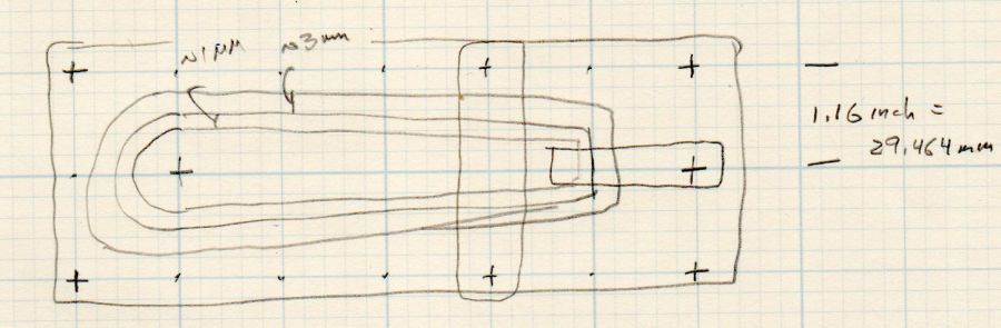
    The original doodle with some notions and dimensions that didn’t survive contact with reality:

    Cursor Fixture doodle
    Cursor Fixture doodle

    I have no idea why the Sherline tooling plate has a 10-32 screw grid on 1.16 inch = 29.46 mm centers, but there they are.

  • Soft Vise Jaws

    Soft Vise Jaws

    A Round Tuit™ finally arrived for this long-delayed project:

    Vise soft jaws - installed
    Vise soft jaws – installed

    They’re bandsawed from an impossibly heavy-duty U-shaped aluminum extrusion salvaged from a scrap pile; the flanges are 6 and 7 mm thick. I’ll put in a good word for the Proxxon 10/14 TPI blade, because it goes through aluminum plate like butter.

    The wood strip under the top flange raises the fillet on the interior angle enough to let the extrusion sit flat on the top vise jaw and square against the gripping side. It’s held in place with double-sided carpet tape.

    They’re faced with a rubber sheet I thought was twice as thick when I picked it out of the Big Box o’ Squishy Sheets, but turned out to be two thinner sheets invisibly stuck together. Carpet tape holds one of the sheets to the jaw; I expect the other sheet to fall off in short order.

    You’re supposed to embed neodymium magnets in the jaws to hold them to the vise. As far as I can tell, they’re perfectly happy to just sit there all by themselves and, anyway, magnets would grow lethally sharp and bulky steel fur coats in short order.

    Squaring the long edge didn’t pose much of a problem:

    Vise soft jaws - squaring edge
    Vise soft jaws – squaring edge

    Tidying the ends, however, required more setup:

    Vise soft jaws - squaring ends
    Vise soft jaws – squaring ends

    That’s the Sherline Tilting Angle Plate at 90°, with barely enough room on the far side for the base of a Starrett Double Square to set the extrusion vertical; the hand clamp holds it in place while tightening the step clamps. It sits on an aluminum sheet to put its upper end three smidgens over the angle plate, letting me flycut one smidgen for a clean edge.

    Now I can retire the old soft jaws, which have served for too many decades and are far too ugly to show; improvised from weatherstripping glued to bent-square copper pipe and intended as a quick fix. You know how that goes …

  • Reversible Belt Buckle: Setscrew

    Reversible Belt Buckle: Setscrew

    The post in my reversible belt buckle popped out again, a year after punching it back in place, so it’s time to do a better job.

    Grab the buckle in the Sherline vise, center on the post hole, and drill a #38 = 2.58 mm hole:

    Reversible Belt Buckle - cross drilling
    Reversible Belt Buckle – cross drilling

    Tap it M3×0.5, clean out the hole, tap the post + spring back in place, dab threadlocker on the shortest M3 setscrew from the assortment, snug down on the post, and reinstall the belt:

    Reversible Belt Buckle - M3 setscrew installed
    Reversible Belt Buckle – M3 setscrew installed

    Looks like it grew there, doesn’t it?

    Now, as my buddy dBm will remind me, the real problem is too much weight in the saddle, but this fix should move the symptoms elsewhere …

  • Tek Circuit Computer: Cursor Hairline Scraping

    Tek Circuit Computer: Cursor Hairline Scraping

    Engraving a PETG sheet with a diamond drag engraver on the Sherline and filling the scratch produces a good-looking hairline, but there’s a tradeoff between having the protective sheet pull the paint out of the scratch and having the crayon scuff the unprotected surface. This time around, I scribbled the crayon through the protective film, let it cure for a few days, then scraped the surface to level the paint and see what happens.

    First, an unscraped cursor:

    Tek CC - Cursor red lacquer - plain - overview
    Tek CC – Cursor red lacquer – plain – overview

    Peeling the transparent protective film:

    Tek CC - Cursor red lacquer - plain - partial peel
    Tek CC – Cursor red lacquer – plain – partial peel

    The hairline is solidly filled:

    Tek CC - Cursor red lacquer - plain - peeled
    Tek CC – Cursor red lacquer – plain – peeled

    Scribbling another cursor the same way, then scraping the protective film to flatten the shredded edges:

    Tek CC - Cursor red lacquer - scraped - overview
    Tek CC – Cursor red lacquer – scraped – overview

    The hairline remains filled, but not as completely:

    Tek CC - Cursor red lacquer - scraped - partial peel
    Tek CC – Cursor red lacquer – scraped – partial peel

    A closer look:

    Tek CC - Cursor red lacquer - scraped - peeled
    Tek CC – Cursor red lacquer – scraped – peeled

    Scraping the crayon off the film removes a substantial amount of paint from the hairline, but, on the upside, the protective film does exactly what it says on the box and the PETG surface remains pristine.

    Both hairlines are, at least eyeballometrically, Just Fine™ for their intended purpose.