Ed Nisley's Blog: Shop notes, electronics, firmware, machinery, 3D printing, laser cuttery, and curiosities. Contents: 100% human thinking, 0% AI slop.
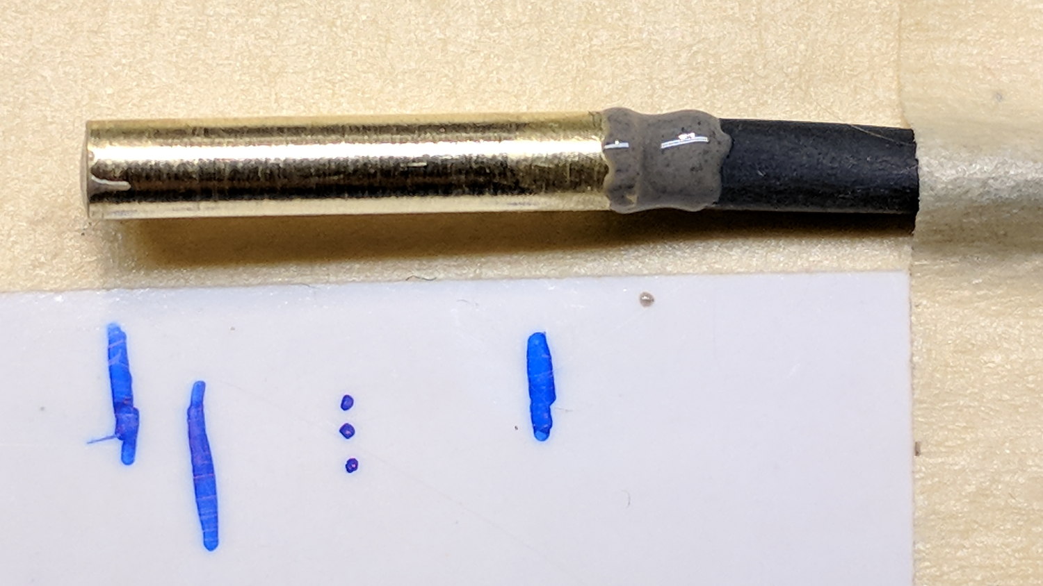
Emboldened by Erik’s suggestion to file the end of a smashed Sakura pen, I filed a notch around the metal snout, snapped it off, and pulled on the tip:
Sakura pen – extended nib
Come to find out the end of the snout is compressed around the nib and holds it in place. I don’t know how long the fiber cylinder might be, but it slides right out of the pen body.
So I squished the snout just a little, snipped off the metal tip, filed the fiber cylinder’s end to a point, and … it sorta-kinda works, but it’ll never again be a very good pen.
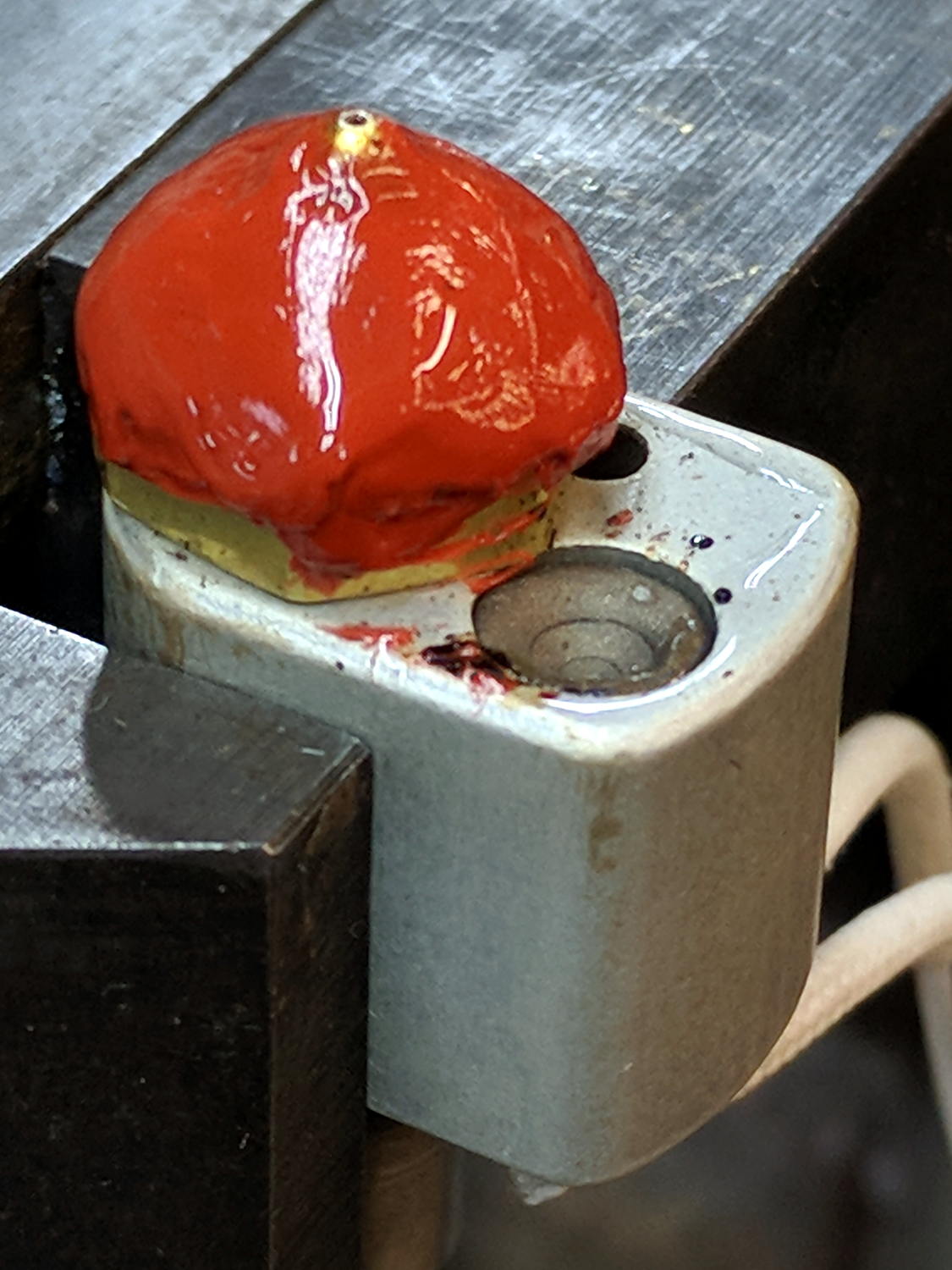
Quite some time ago, Vedran described a silicone boot he put over the nozzle. Rather than building a mold and casting the RTV, I threw caution to the winds, ignored any acetic acid corrosion issues, and troweled a layer of RTV on the nozzle:
M2 – nozzle silicone – applied
That’s JB Weld Hi-Temp Red Silicone, rated up to 550 °F = 290 °C continuous operation, so it should be Just Fine at PETG’s usual 250 °C.
I slipped the rebuilt thermistor into its hole, slipped the hot end back into the M2’s extruder, raised it a bit higher than it was before, fired up the M2, and …
Home the X axis
Set X offset: G28 X-100
Move it off to the right: G0 X130
Home the Z axis
Set Z offset: G28 Z-2.15
The Y axis is pretty near the middle, so it’s all good
Move the nozzle to the middle: G0 X0
Move the platform to Z=0: G0 Z0
N.B.: I have the XY=0 origin in the middle of the platform, so don’t do like I do and expect it to work if you put the origin elsewhere.
Then loosen the hot end clamp, slide the hot end down until the nozzle touches the platform, tighten the clamp, and the tip of the nozzle should be pretty close to where it started out:
M2 – nozzle silicone – Z 0.0 set
The microswitch in the background senses the top of the platform, eliminating all the putzing around everybody else does to get a consistent Z offset. I verified the switch trip point by sliding my trusty Starrett No. 270 Taper Gage under the lever until it tripped at 2.1 mm; about as close to 2.15 mm as one might hope for.
The PETG hairs I described in the original post were conspicuous by their absence. It’s too early to tell if the silicone coating is a complete cure, but at least it’s not causing any obvious problems.
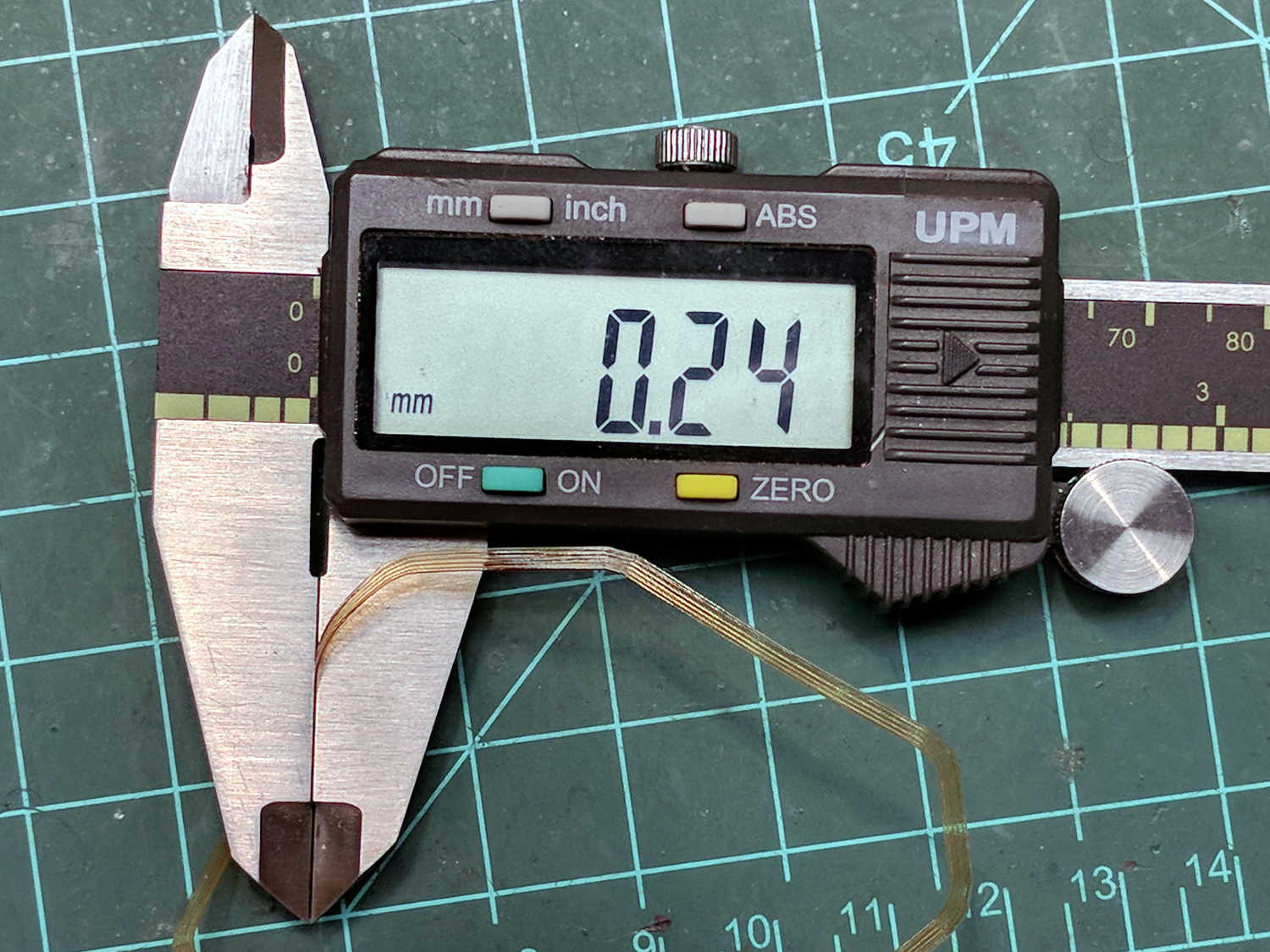
The skirt around those parts came out close enough to its nominal 0.25 mm layer thickness:
M2 – nozzle alignment – skirt thickness
I must print some calibration squares to verify the platform alignment and the overall height.
Just for completeness, here’s looking up at the new nozzle, snug inside its fuzzy fiberglas insulating wrap, with a PETG strand drooling from its orifice:
M2 – nozzle silicone – bottom view
I really should order a couple of thermistors, a cartridge heater, and maybe a nozzle …
The MAXTEMP error killing the M2 while printing the bar clamp mounts (probably) came from a short in the thermistor pellet that lowered the thermistor resistance and raised the calculated temperature. I manually heated the extruder and, although the temperature stabilized at 250 °C, the history plot showed irregular downward jogs from increasing resistance. Whenever this constellation of symptoms appears on the M2 forums, I always recommend ordering another thermistor or two, so …
Start by turning a 1/8 inch OD brass tube down to 3.00 mm, parting off a suitable length, facing the ends:
M2 – thermistor brass tube turning
Countersink the ends just for pretty.
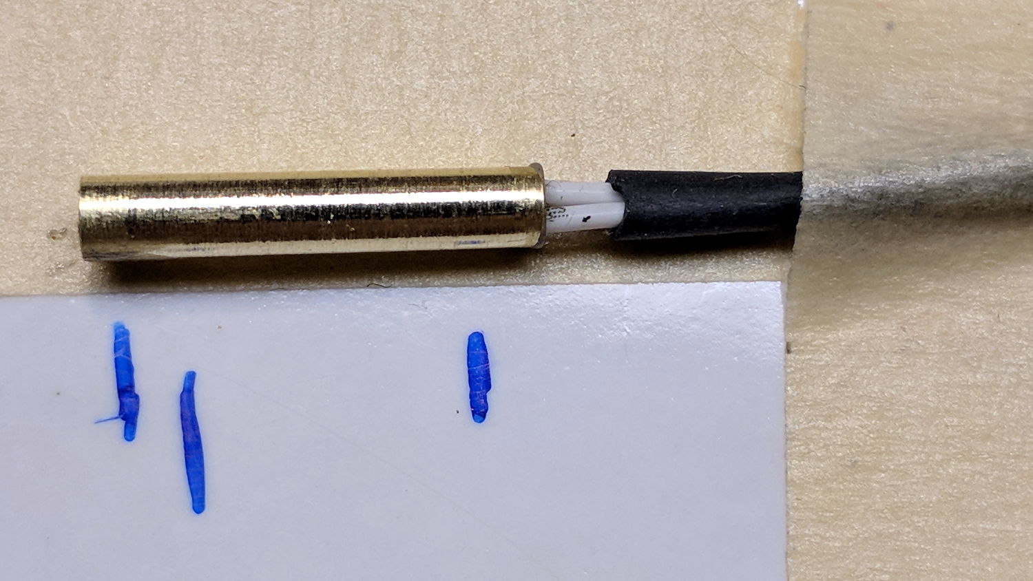
The tube should be a slip fit in the hot end:
M2 – hot end thermistor – turned brass tube
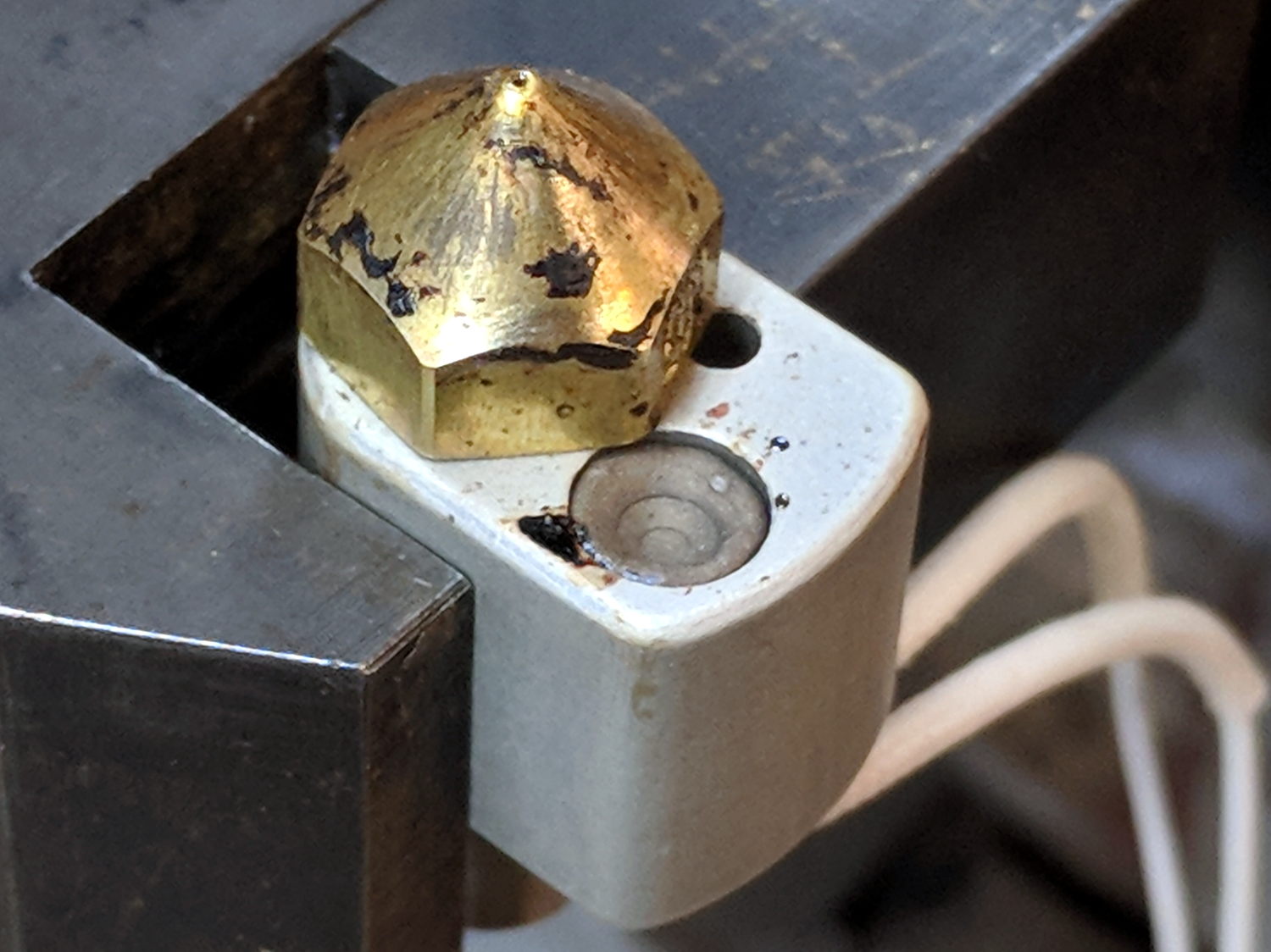
While I had the hot end on the bench, I scuffed the nozzle to remove (most of) the baked-on crud:
M2 – nozzle silicone – cleaned nozzle
The plan is to seal the thermistor bead inside the tube with JB Weld epoxy, which I’ve verified (!) to work at extrusion temperatures, depending on the epoxy to insulate the wiring and immobilize all the pieces.
Harvest the original wire harness from the defunct thermistor, solder to the bead, lay out guide lines:
M2 – thermistor – assembly 1 layout
Slobber epoxy over everytyhing, fill the tube, insert bead into tube, stabilize with tape:
M2 – thermistor – assembly 1 curing
Verify connectivity through the thermistor and isolation from the brass tube, then return upstairs to warm up thaw out while the epoxy cures.
At this point, the observant reader should be thinking “Uh, Ed, that bead looked a tad large. Are you absolutely sure … ?”
Halfway up the basement stairs I realized I’d meticulously entombed a 10 kΩ thermistor, not the 100 kΩ thermistor used in the M2’s hot end. You can easily verify the resistance, as I did, with a quick web search; I have hella-good SEO for some specific topics.
Back to the lab …
Fortunately, JB Weld has a pot life over an hour, so extract the wrong bead, unsolder, install the right thermistor using snippets of insulation harvested from the original wiring, realign components:
M2 – thermistor – assembly 2 layout
Reapply epoxy:
M2 – thermistor – assembly 2
Re-verify resistances, return upstairs, fast-forward through the night, have another good idea …
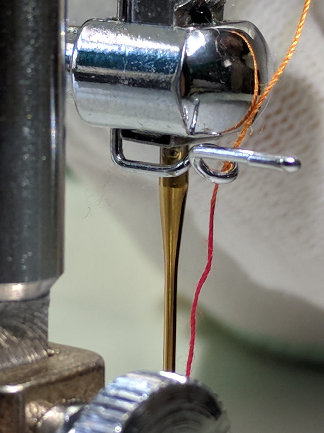
It turns out the thread guide on Mary’s new Juki TL-2010Q sewing machine has what’s euphemistcally known as “negative clearance” with the ruler foot she uses for quilting patterns. With the foot raised to move the cloth, inadvertently pressing the foot pedal or turning the handwheel can crunch the thread guide against the foot.
As you might expect, the intricately bent wire thread guide doesn’t survive the encounter. Not having a spare ready to hand and not knowing quite what it should look like, I reshaped it as best I could:
Juki thread guide – in vise
It worked moderately well:
Juki thread guide – reshaped installed
The automatic needle threader wasn’t reliable, but she could cope until the replacements arrived.
Comparing the new one (left) with the wrecked one (right) shows I didn’t re-bend the loop tightly enough, putting the end on the right at the wrong angle:
Juki thread guide – new vs reshaped
It’s the kind of shape you can duplicate by the thousands with a production machine, but can’t make at home without entirely too much tedious effort.
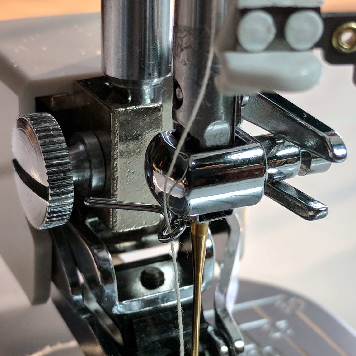
The new one works fine, seen here in front of a walking foot, with the auto-threader looming in the upper foreground:
It adds a festive touch when done up in orange PETG:
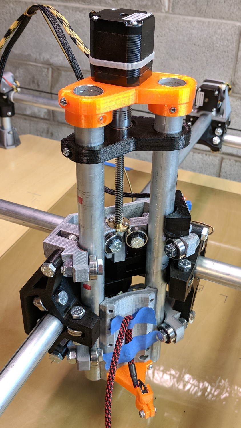
MPCNC – Reinforced Z Motor Mount
The attentive reader will note the missing head of the screw anchoring the mount to the left Z rail. Apparently a #32 drill was a bit too small to let the randomly chosen self-tapping screws thread themselves into EMT; they probably anchored a PCB to the plastic case of a long-forgotten lump of consumer electronics.
It should last long enough for something else to let go …
Two more umbrella struts snapped and required the same repair, but, having drained all the suitable snippets from the Box o’ Brass Cutoffs, some lathe work was in order:
Umbrella strut splint – cutting
I used the carbide insert in the mistaken belief it’d be less grabby, then applied the cutoff tool.
Break the edges, slide splints over the ribs, slobber epoxy on the struts, slide splints into place, apply masking tape for a bit of compression & alignment, and let it cure: