The Smell of Molten Projects in the Morning

Ed Nisley's Blog: Shop notes, electronics, firmware, machinery, 3D printing, laser cuttery, and curiosities. Contents: 100% human thinking, 0% AI slop.

Tag: Repairs

If it used to work, it can work again

  • APRS/Voice HT Interface: Baofeng Mods

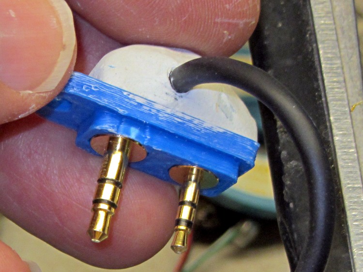
    My carefully contrived plug plates for Wouxun radios:

    Wouxun plug plate - epoxy cap
    Wouxun plug plate – epoxy cap

    … of course don’t fit the Baofeng radio. This being in the nature of a final fix, I chopped off enough protrusions to make the remainder fit snugly into the recess.

    APRS-voice HT interface - Baofeng mods
    APRS-voice HT interface – Baofeng mods

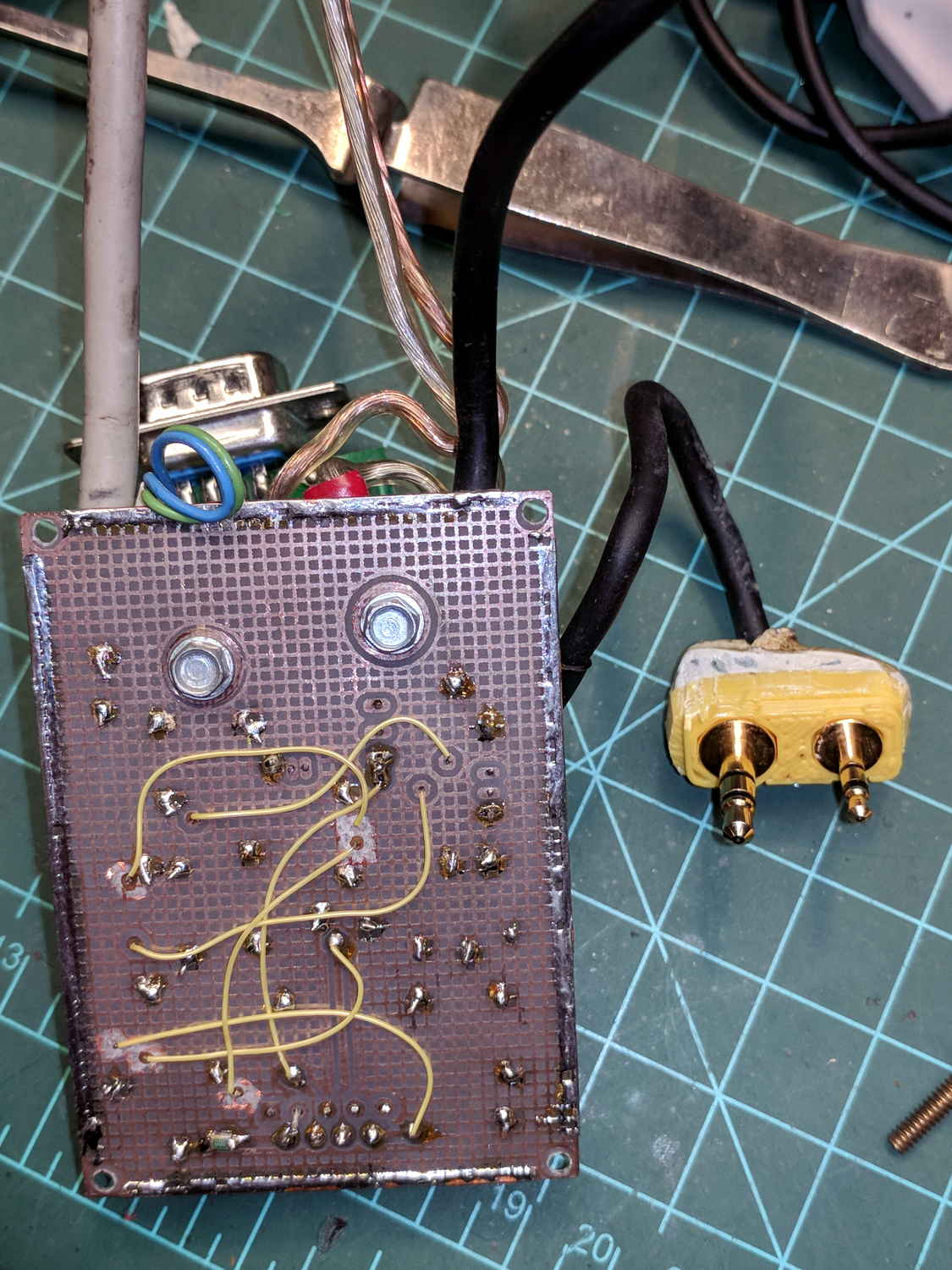
    The case containing the TinyTrak3 GPS board and the APRS-voice adapter PCB of course doesn’t fit in place of the Baofeng battery pack, so I replaced the battery contact studs with simple 4-40 screws to prevent heartache & confusion.

    Based on one ride, both Baofeng batteries have very little capacity left after several years on the shelf, which comes as absolutely no surprise whatsoever.

  • Water Hardness

    A water hardness test strip recently arrived from Morton Salt:

    Water harness test
    Water harness test

    I call it between 7 and 15 gpg. Based on the feel of the water just before regeneration, I’d been guesstimating 15 gpg, so it’s within reason.

    I’ll back the softener off to 10 gpg and see what happens.

  • Streaming Radio Player: RPi and OLED Updates

    Because the OLED driver came from the pip package manager, not the Raspberry Pi’s system-level apt package manager, it (or they, there’s plenty of code under the hood) don’t get updated whenever I do system maintenance. The doc says this should do the trick:

    sudo -H pip install --upgrade luma.oled
    

    However, it turns out the new version has a slightly longer list of pre-requisite packages, causing the update to go toes-up at a missing package:

    Could not import setuptools which is required to install from a source distribution.
    Please install setuptools.
    

    So update (or install, for the new ones) the missing pieces:

    sudo apt-get install python-dev python-pip libfreetype6-dev libjpeg-dev build-essential
    

    Doing so produced a backwards-compatibility error in my Python code:

    ... change ...
    from luma.core.serial import spi
    ... into ...
    from luma.core.interface.serial import spi
    

    The motivation for all this fuffing and fawing came from watching some OLEDs wake up completely blank or become garbled in one way or another. Evidently, my slower-speed SPI tweak didn’t quite solve the problem, although it did reduce the frequency of failures. I have decided, as a matter of principle, to not embrace the garble.

    Soooo, let’s see how shaking all the dice affects the situation.

    It’s entirely possible the OLED controllers don’t quite meet their specs, of course, or have begun deteriorating for all the usual reasons.

  • J5-V2 Flashlight: Front End Rattle

    After a year of fairly light use, the lens holder (and “attack ring”) of my J5-V2 flashlight worked loose and began to rattle. The ring holding the lens in place turned out to be finger-loose, but that wasn’t the entire problem, so I removed it and looked inside:

    J5-V2 Flashlight - LED view
    J5-V2 Flashlight – LED view

    The mysterious alien egg resides on the upper-right side of the LED emitter.

    The aluminum ring holding the LED assembly in place was also finger-loose, so I unwound it to take the whole front end apart:

    J5-V2 Flashlight - front parts
    J5-V2 Flashlight – front parts

    Reassembly with a few dabs of Loctite in appropriate places should prevent future rattles.

    Given the number of … issues … accompanying this thing, I’d say it’s not been a good cost performer. The Anker LC40 and LC90 flashlights work much better.


  • Streaming Radio Player: OLED Garble

    Even in the dim light of dawn, it’s obvious slowing the SPI clock to 1 MHz didn’t quite solve the problem:

    RPi OLED display - garbled
    RPi OLED display – garbled

    The display started up fine, became encrypted during the next few hours, and remained garbled as the track information changed. This is almost certainly a bad SPI transfer trashing the OLED module’s control registers.

    Dropping the clock to the absolute minimum of 0.5 MHz didn’t help, either:

    serial = spi(device=0,port=0,bus_speed_hz=500000)
    device = sh1106(serial)
    

    This particular display woke up blank after loading the new code, then worked OK after another reset. The other streamers lit up as expected on the first try, so the slower SPI isn’t making the situation instantly worse.

    Running the clock at 1 MHz definitely reduced the failure rate, which suggests it’s a glitchy thing.

    Good embedded systems practice suggests resetting the entire display from scratch every now and again, but my streamer code has no concept of elapsed time. Opening that particular can o’ worms would almost certainly result in an on-screen clock and I do not want to go there.

    I suppose I must get a new oscilloscope with SPI bus decoding to verify all the SPI setup and hold times …

  • Suet Feeder Temporary Fix

    The neighborhood raccoons made off with our steel-cage suet feeder, leaving a dangling chain, several puzzled woodpeckers, and a potential gap in Mary’s FeederWatch data. A quick Thingiverse search turned up a likely candidate and a few hours of 3D printing produced a replacement:

    3D printed suet feeder
    3D printed suet feeder

    The cheerful party colors just sort of happened after I realized orange wasn’t the new steel.

    I bandsawed the top plate from an acrylic sheet, rather than devote several hours to printing a simple disk with two slots. Said slots came from a bit of freehand work with the drill press, a step drill bit, and a nasty carbide milling bur(r).

    The loops holding the chains won’t last for long, as hairy and red-bellied woodpeckers land with thump.

    It hangs from the stub of a former ski pole, loosely secured to the bracket holding the former feeder, and extending another two feet over the abyss beyond the patio. I doubt the raccoons will remain daunted for long, but maybe they’ll catch a heart attack when it collapses.

  • M2 Platform Alignment and Nozzle Height Check: Z Offset Confusion

    A set of five calibration boxes will check both platform alignment and extruder settings:

    Calibration Squares - rectified
    Calibration Squares – rectified

    Those boxes have three threads in their walls and stand 3.0 mm tall:

    Calibration Boxes - alignment layout - corner detail - Slic3r preview
    Calibration Boxes – alignment layout – corner detail – Slic3r preview

    The first pass measurements:

    Calibration Boxes - initial measurements - 2018-02-07
    Calibration Boxes – initial measurements – 2018-02-07

    The skirt is scant at 0.20 mm, the boxes are 0.15 mm short at 2.85 mm, and the walls are 0.03 mm too thin. Some Z offset adjustment seems in order, as the first few layers (on the left) came out grossly squished:

    Calibration box - 2.85 - detail
    Calibration box – 2.85 – detail

    However, the box heights came out sufficiently uniform to show the platform alignment remains just fine.

    Long ago, I moved the Z endstop switch to the X axis gantry, where it can directly sense the platform position:

    M2 - V4 hot end - Z endstop switch
    M2 – V4 hot end – Z endstop switch

    Putting it there replaces all the mechanical putzing and adjusting cute little screws / bolts / nuts / spacers / suchlike with a simple offset in the startup G-Code:

    G28 Z-2.15				; home Z to platform switch, with measured offset
    

    So I changed the startup G-Code in Slic3r to use G28 Z-2.30, sliced a single box in the middle of the platform, printed it, and … it came out exactly the same height: 2.85 mm.

    Huh.

    To make a very long story short, it turns out Marlin 1.1 ignores the numeric parameter in G28. When I updated the firmware to that version, I had changed the Configuration.h file to include the homing offsets:

      #define MANUAL_X_HOME_POS -100
      #define MANUAL_Y_HOME_POS -127
      #define MANUAL_Z_HOME_POS -2.15
    

    So, with the same offset burned into the firmware, it looked like the startup G-Code was Doing The Right Thing. I never deleted the offset from the startup G-Code and, at some point, Marlin stopped supporting the numeric parameter.

    Huh.

    However, the X and Y homing offsets must be hardcoded, because I want the XY origin in the middle of the platform to match my original OpenSCAD part designs. Everybody else prefers the XY origin in the front-left corner. FWIW, in Marlin 1.1-RC5 (two years old by now), the #define BED_CENTER_AT_0_0 constant appears only in that line and nowhere else in the source code. Maybe it was a change in progress back then?

    Anyhow, rather than hardcode the Z offset again, I set it to 0.00:

      #define MANUAL_X_HOME_POS -100
      #define MANUAL_Y_HOME_POS -127
      #define MANUAL_Z_HOME_POS  0.0
    

    Recompile and reload the firmware, then change the startup G-Code to use G28 Z without the offset.

    Doing so means I can measure and adjust the actual Z offset with M206, then store the value in EEPROM with M500:

    M206 Z-2.25
    M500
    

    I went a little short at -2.25, for reasons I cannot explain now.

    Measuring the offset goes like this:

    • Zero the offset: M206 Z0
    • Move the extruder off to the right: G0 X135
    • Home Z: G28 Z
    • Get some air under the nozzle: G0 Z4.0
    • Measure the actual clearance, perhaps using your taper gauge, at (let’s say) 1.7 mm
    • Set (1.7 – 4.0) as the offset: M206 Z-2.3
    • Print a box and adjust the offset accordingly

    Using my actual measurement, not the for-instance example, I resliced the box, printed it, and it came out at 2.94 mm, just slightly short, so I re-tweaked the offset to Z-3.28 and re-stored it.

    Embiggening the wall thickness turned out to be a matter of updating the filament diameter. I measured the start of the current spool of orange PETG at 1.75 mm, the same as the previous natural PETG spool, but the current section is 1.70 mm. Plugging that into Slic3r, reslicing, and reprinting produced a dead-on square: 3.00 mm tall with 1.20 mm walls:

    Calibration Square series
    Calibration Square series

    The skirt now comes out at 0.25 mm, the way it should, too. The difference between the original 0.20 mm skirt and 0.25 mm suggests the squashed center thread (of the three in the skirt around the first set of five boxes) forced the two adjacent threads to become a bit taller, for lack of somewhere for the excess plastic to go on one side of each thread, and the nozzle rode higher than you’d (well, I’d) expect from the bare numbers.

    The picture is missing a few squares in the middle, because I couldn’t believe changing the G28 Z-2.15 offset had no effect. It was easier to believe I’d inadvertently loaded the wrong file than the software / firmware was doing something wrong.

    However, during the course of the adventure, I established M851 does exactly nothing in this context, perhaps because it applies to some different type of homing / probing / mesh leveling / whatever. You can set the Z offset with several other G-Code and M-Code commands, but the documentation isn’t always forthcoming about how the various methods interact and different firmware uses identical codes for completely different functions, so proceed with Exceedingly Great Caution.

    In any event, it’s much easier and faster to adjust the printer & slicing parameters by measuring test boxes than by puzzling over actual prints, so …

    The OpenSCAD source code as a GitHub Gist:

    // Simple calibration boxes
    // Thin wall open box – verify Extrusion Multiplier
    // Solid box – verify infill settings
    // Ed Nisley – KE4ZNU
    // https://softsolder.com/
    Layout = "Open"; // Open Solid
    Texting = ""; // text message on solid box or empty string to suppress
    //——-
    //- Extrusion parameters must match reality!
    ThreadThick = 0.25;
    ThreadWidth = 0.40;
    Protrusion = 0.1; // make holes end cleanly
    function IntegerMultiple(Size,Unit) = Unit * ceil(Size / Unit);
    //——-
    // Dimensions
    WallThick = 3.0 * ThreadWidth;
    echo(str("Wall thickness: ",WallThick));
    BoxSize = 40.0;
    echo(str("Overall size: ",BoxSize));
    NominalHeight = 3.0;
    echo(str("Nominal height: ",NominalHeight));
    Height = IntegerMultiple(NominalHeight,ThreadThick);
    echo(str("Actual height: ",Height));
    Rotation = 0; // 45 to exercise X and Y axis motors at same time
    CornerRadius = max(2.0, 2.0 + WallThick);
    CornerSides = 8*4;
    //——–
    module Solid() {
    difference() {
    hull()
    for (i=[-1,1], j=[-1,1])
    translate([i*(BoxSize – 2*CornerRadius)/2,j*(BoxSize – 2*CornerRadius)/2,0])
    cylinder(r=CornerRadius,h=Height,$fn=CornerSides);
    if (len(Texting))
    translate([0,0,-Protrusion/2])
    linear_extrude(height=3*ThreadThick + Protrusion)
    mirror([1,0,0])
    text(text=Texting,size=6,spacing=1.05,font="ITC Zapf Chancery:style=Italic",halign="center",valign="center");
    }
    }
    module Thinwall() {
    difference() {
    Solid();
    hull()
    for (i=[-1,1], j=[-1,1])
    translate([i*(BoxSize – 2*CornerRadius)/2,j*(BoxSize – 2*CornerRadius)/2,-Protrusion])
    cylinder(r=(CornerRadius – WallThick),h=(Height + 2*Protrusion),$fn=CornerSides);
    }
    }
    //——-
    rotate(Rotation)
    if (Layout == "Open")
    Thinwall();
    else
    Solid();