The Smell of Molten Projects in the Morning

Ed Nisley's Blog: Shop notes, electronics, firmware, machinery, 3D printing, laser cuttery, and curiosities. Contents: 100% human thinking, 0% AI slop.

Tag: Repairs

If it used to work, it can work again

  • Fireball Island Figures

    A cousin asked if my 3D printer could replace some figures gone missing from their old Fireball Island game board, a classic apparently coming out in a new & improved version.

    Fortunately, solid models exist on Thingiverse:

    Fireball Island figure - Thingiverse 536867
    Fireball Island figure – Thingiverse 536867

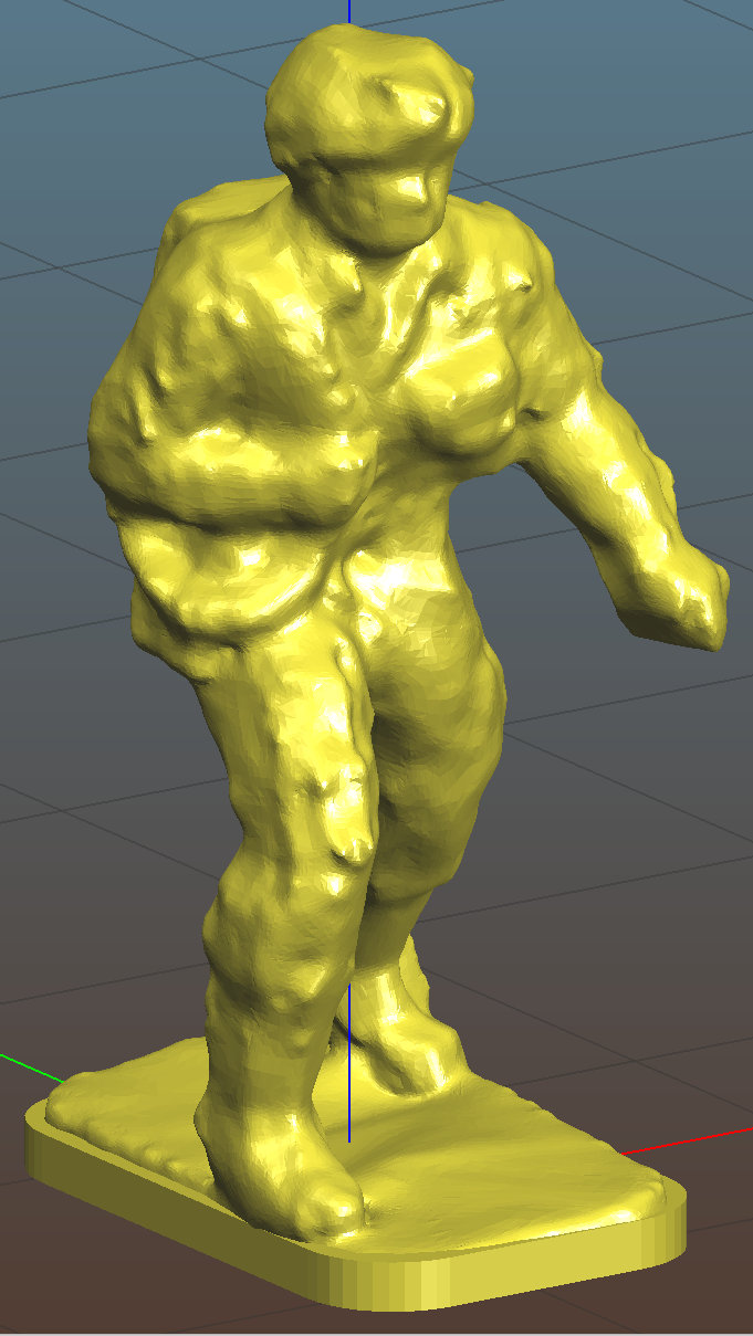
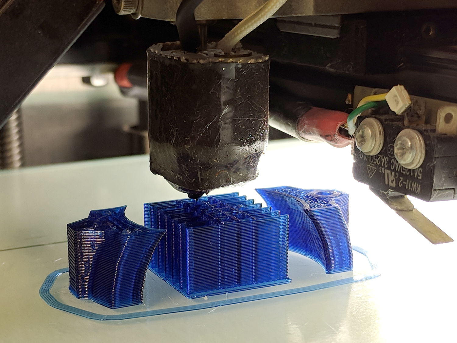
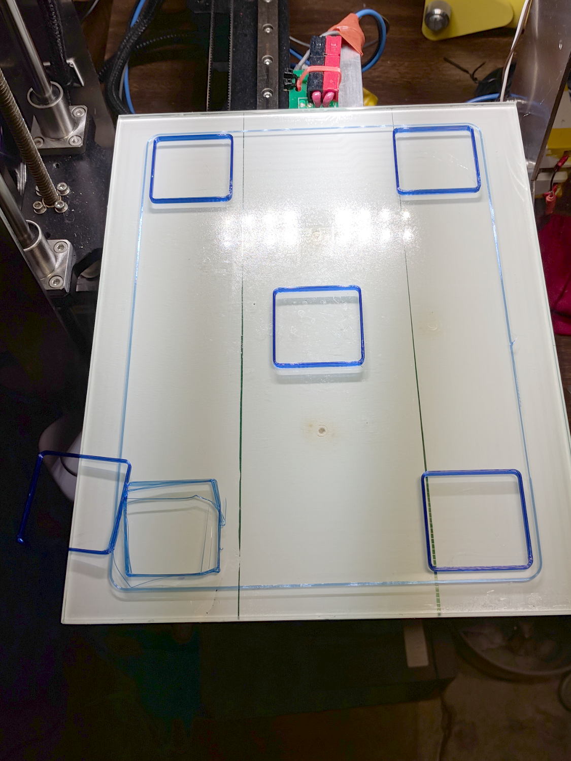
    Unfortunately, the left arm requires support, which Slic3r supplies with great exuberance:

    Fireball Island figure - Slic3r support
    Fireball Island figure – Slic3r support

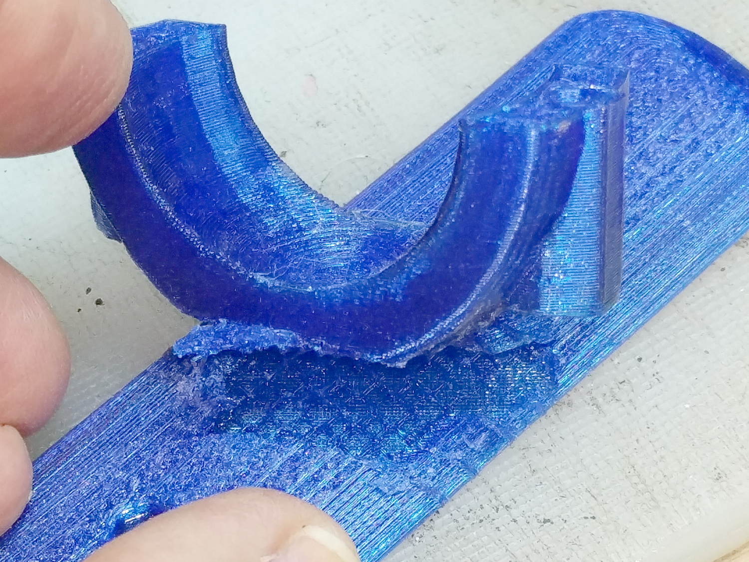
    The vast tower on the figure’s right side (our left) seemed completely unnecessary, not to mention I have no enthusiasm for the peril inherent in chopping away so much plastic, so I replaced it with a simple in-model pillar:

    Figure Support Mods
    Figure Support Mods

    The pillar leans from an adhesion-enhancing lily pad and ends one layer below the left hand, with all dimensions and angles chosen on the fly to make the answer come out right.
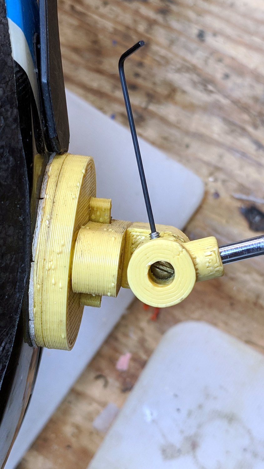
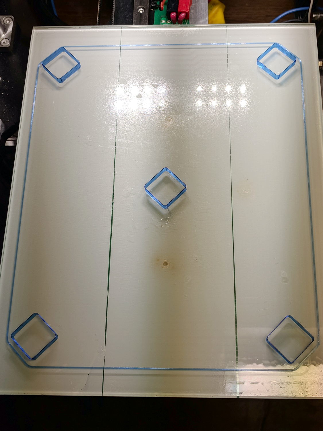
    Works like a champ:

    Fireball Island Figures - orange - on platform
    Fireball Island Figures – orange – on platform

    The dark band down the middle comes from the Pixel’s shutter.

    They emerged with some PETG hair, the removal of which I left as an end-user experience.

    I mailed a small box containing figures printed in my (limited!) palette of four colors, some spares Just In Case™, and a few QC rejects showing the necessity of lily pads.

    Game on!

    The OpenSCAD source code as a GitHub Gist:

    // Adding support under Fireball Island figure arm
    import("/mnt/bulkdata/Project Files/Thing-O-Matic/Fireball Island/Fireball Island figure – 100k.stl", convexity=5);
    translate([6.5,-4.0,0]) {
    intersection(){
    translate([-10/2,-10/2,0])
    cube([10,10,11.6],center=false);
    rotate([0,-5.0,0])
    rotate(180/6)
    cylinder(d=4.0,h=30,$fn=6,center=true);
    }
    translate([8/4,0,0])
    rotate(180/6)
    cylinder(d=8,h=0.2,$fn=6);
    }
  • Tektronix AM503 Current Probe Amplifier: Failed Electrolytic Capacitor

    The same Tektronix AM503 current probe amp with the slightly disconnected JFET developed a nasty 120 Hz hum, which can mean only one thing:

    Tek AM503 - corroded capacitor
    Tek AM503 – corroded capacitor

    Dunno how I missed that while I had the cover off, but there it is. For future reference it’s C165, 47 µF 50 V, with an 8709 date code.

    This being a PCB made back in the old days, likely with self-adhesive tape strips, the component pads inside ground and power pours lack thermal isolation decorations.

    The solder joints on the bottom side looks better than these, honest:

    Tek AM503 - replaced capacitor
    Tek AM503 – replaced capacitor

    The new cap is 56 µF 50 F, which seems Close Enough.

    The other caps have reasonable ESRs, but I must lay in a stock of high-voltage ‘lytics, as the “new” one is definitely old enough to know better, too.

    Now that I check, the amp still produces a very low amplitude 2 MHz sine wave on its 1 mA/div and 2 mA/div settings, suggesting Something Is Not Right™ in the front end, but it works well enough to let me defer that fix until later.


  • Frayed Power Drop

    The neutral conductor is down to its last three strands:

    Damaged neutral - over Redondo near pole 62859
    Damaged neutral – over Redondo near pole 62859

    Perhaps the power drop got snagged twice, because there’s a splice only a few feet away:

    Damaged neutral and splice - over Redondo near pole 62859
    Damaged neutral and splice – over Redondo near pole 62859

    Spotted overhead on Redondo near Rt 376 during an evening walk. I reported it using Central Hudson’s dead streetlight page, because there seems no other way to get their attention. It may be the homeowner’s responsibility, in which case a second splice will surely appear after the next power outage.

  • New York State Bike Route 9: Maintenance Thereof

    One might expect the NYS Department of Transportation to maintain New York State Bike Route 9, a.k.a. NYS Rt 376 from Poughkeepsie to Red Oaks Mill, in a bicycle-aware manner.

    One would be mistaken.

    The most recent patch strip very carefully avoids the deteriorated shoulder, all the way around the curve:

    Rt 376 SB patch - shoulder deterioration - marker 1111 - 2018-08-23
    Rt 376 SB patch – shoulder deterioration – marker 1111 – 2018-08-23

    The weeds growing in the serrated shoulder add a decorative counterpoint to the black asphalt patch in the travel lane:

    Rt 376 SB patch - shoulder grass - marker 1110 - 2018-08-23
    Rt 376 SB patch – shoulder grass – marker 1110 – 2018-08-23

    It was a rather large repair crew:

    Rt 376 Road Repair Crew - marker 1110 - 2018-08-23
    Rt 376 Road Repair Crew – marker 1110 – 2018-08-23

    The crew chief said they were there because “somebody wrote a letter” describing the conditions. I suppose that would be me, although after half a year it’s hard to establish causation, let alone correlation.

    He also says no details of the letter reached him, which explains why they laid the patches in the travel lane, rather than repairing the conditions I described. He was adamant they were doing the best they could with the inadequate manpower, materials, and time available for the projects.

    There are absolutely no requirements to consider bicyclist safety in their repairs, so laying asphalt over the shoulder never happens.

    NYS DOT’s Bicycling FAQ says I should “take the lane” around that curve, due to the deteriorated shoulder, to ensure motorists pass only when it’s safe.

    Whenever I offer to take a NYS DOT bureaucrat on an inspection ride along their roads, they never have the time. Of course, they don’t “work” on weekends, so they’re unwilling to join me on a pleasant ride around the area some Saturday or Sunday morning.

    Just another day of bicycling along NYS DOT’s “complete streets” …


  • Bike Helmet Mirror Mount Tightening

    Almost exactly three years later, it’s time to tighten the helmet mirror mount screws:

    Helmet mirror mount - bottom view - setscrew
    Helmet mirror mount – bottom view – setscrew

    That’s a 0.035 inch = 35 mil hex wrench, of which Eks reminds me “Any time your design requires a tiny [obscene gerund] wrench, you’re doing it wrong”.

    The sequence goes like this:

    • Loosen that tiny setscrew
    • Unscrew & remove the mirror boom
    • Remove brass screw & azimuth pivot
    • Tighten screw in elevation pivot
    • Tighten tiny setscrew on elevation arc
    • Reinstall & tighten azimuth pivot
    • Reinstall mirror boom
    • Tighten tiny setscrew

    Going strong after seven years!

  • Tour Easy Daytime Running Light: First Fracture

    A wind gust pushed Mary’s bike over with the daytime running light on the downward side:

    Fairing Flashlight Mount - Fracture
    Fairing Flashlight Mount – Fracture

    Frankly, it’s better to have a cheap and easily replaceable plastic widget break, instead of something expensive and hard to find.

    Because we live in the future, a replacement part was just a few hours away:

    M2 - Nozzle Z Offset Recal - DRL Clamp
    M2 – Nozzle Z Offset Recal – DRL Clamp

    Well, a few hours after installing a replacement thermistor and recalibrating the M2, but nested repairs happen every now and again.

    To the road!

  • Makergear M2: Nozzle Z Offset Recalibration

    After a few days of downtime, an Official Makergear Thermistor arrived and is now installed amid a dab of heatsink compound:

    M2 - Thermistor with heatsink compound
    M2 – Thermistor with heatsink compound

    With the hot end set a bit higher than usual, position the platform at Z=0, lower the nozzle to be flat on the platform, tighten the lock screw, then run off a set of large calibration squares:

    M2 - Nozzle Z Offset Recal - first test
    M2 – Nozzle Z Offset Recal – first test

    The scrambled square in the front left says the Z=0 nozzle position came out just a bit too far above the platform and, indeed, the measurements (upper left numbers) say it’s off by 0.15-ish mm:

    M2 Nozzle and Platform Re-Cal Measurements
    M2 Nozzle and Platform Re-Cal Measurements

    Probably a little PETG stuck to the nozzle; I hate adjusting things when they’re burning hot.

    The walls are also thin by a smidge, but the first order of business is to reset the Z offset with M206 Z=-2.15. With that in hand, the second set of squares came out at 3.00 to 3.08 mm (lower left numbers), which I defined to be Close Enough.

    The 0.08 mm variation across the platform isn’t enough to worry about.

    The first skirt threads were too thick and not solidly bonded together, but the second skirt came out normally, with a thickness from 0.21 through 0.30, which is also Good Enough.

    The three-thread walls were still 1.15 mm, rather than 1.20 mm, so the EM should go from 0.95 to 0.95*1.20/1.15 = 1.05.

    Next, a set of single-thread thinwall boxes to verify the Z offset and recheck the Extrusion Multiplier:

    M2 - Nozzle Z Offset Recal - thinwall test
    M2 – Nozzle Z Offset Recal – thinwall test

    They’re dead on 3.00 mm tall, varying by not enough to worry about.

    Their single-thread walls are 0.38 mm, not the intended 0.40, which suggests the EM should become 0.95*0.40/0.35 = 1.00.

    It turns out the filament diameter at this part of the roll is scant of 1.75 mm, maybe 1.73 mm, so I decided to not fiddle with the EM.

    The first production part came out fine:

    M2 - Nozzle Z Offset Recal - DRL Clamp
    M2 – Nozzle Z Offset Recal – DRL Clamp

    The flange around the bottom of the arch support grid (in the middle) is intentional; it’s not an overstuffed first layer. The clamp sections rise from the platform just like they grew there.

    So the M2 is back in operation and I have a spare thermistor on the shelf!