The Smell of Molten Projects in the Morning

Ed Nisley's Blog: Shop notes, electronics, firmware, machinery, 3D printing, laser cuttery, and curiosities. Contents: 100% human thinking, 0% AI slop.

Tag: Repairs

If it used to work, it can work again

  • Cheap Flashlight Boost Converter: Capacitor FAIL

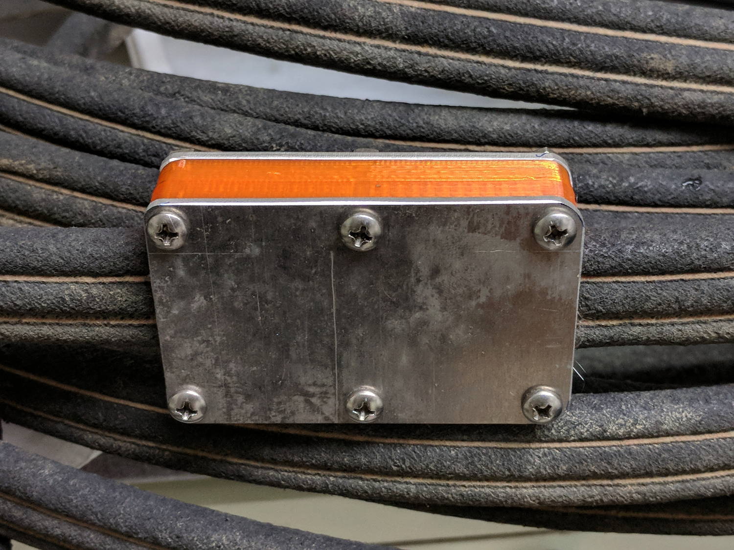
    A long time ago, a pair of white LED + red laser flashlights powered by an AA cell diverged: one flashlight worked fine, the other always had a dead battery. The latter ended up on my “one of these days” pile, from which it recently emerged and accompanied me to a Squidwrench Tuesday session:

    Small Sun flashlight - original wiring
    Small Sun flashlight – original wiring

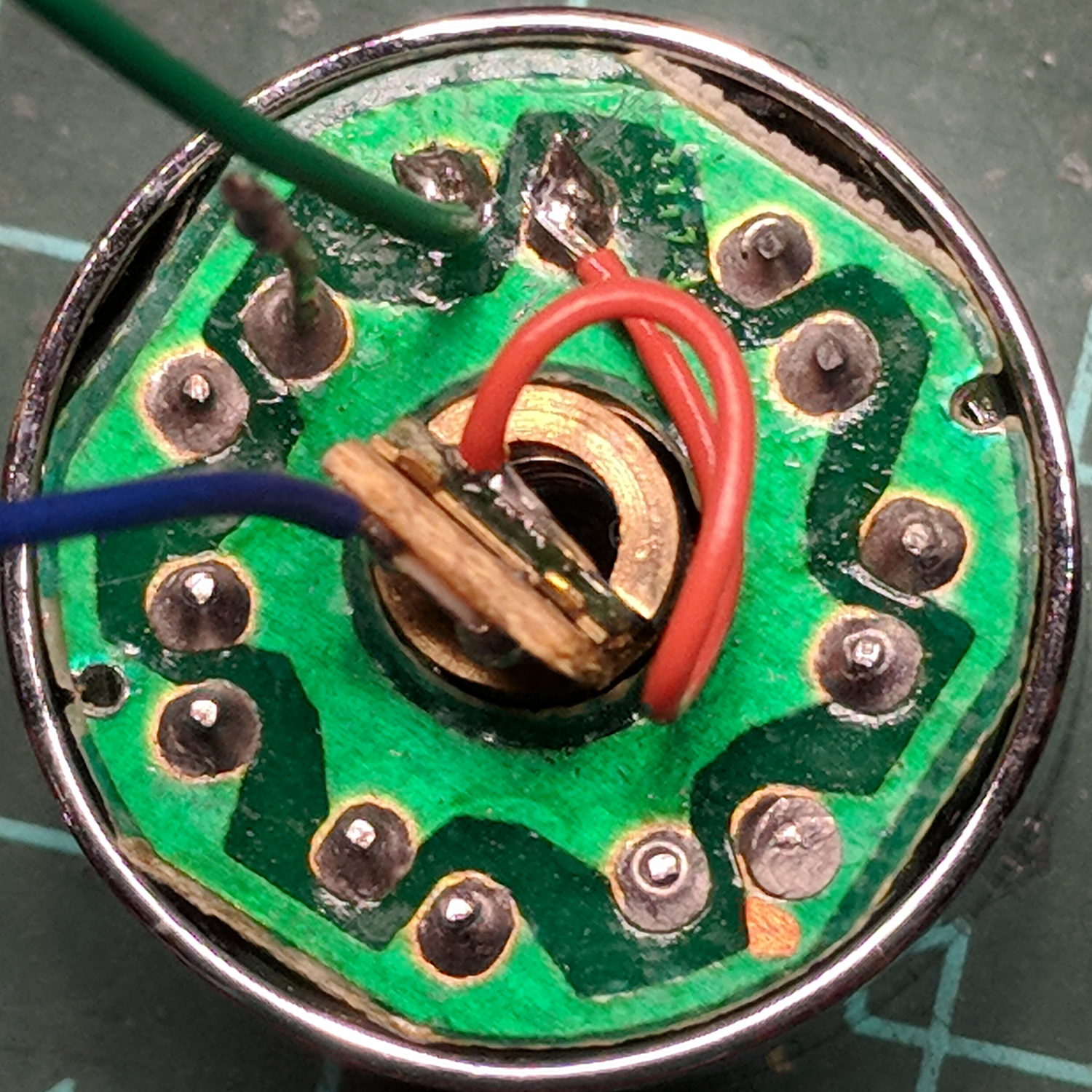
    The black wire trailing from the innards goes to the battery negative terminal, with the aluminum body providing the positive terminal connection to the wavy-washer spring contact visible atop the rear PCB inside the front shell.

    The switch connects each red wire to the battery negative terminal, so there’s a color code issue in full effect. The two red wires burrow through holes in the rear PCB (shown above) and connect to the negative terminal of the laser module (the brass cylinder near the top) and the negative terminal ring on the front PCB holding the seven white LEDs:

    Small Sun flashlight - original wiring - LED laser board
    Small Sun flashlight – original wiring – LED laser board

    Continuing the color code issue, the black wire from the laser is its positive terminal. The out-of-focus wire (an LED pin) sticking up near the top of the picture carries the positive connection to the LED ring. The red wires from the switch are the negative connections for the LEDs and laser.

    Voltages applied to the LED ring and the currents flowing therein:

    Small Sun flashlight - 7x white LED current vs voltage
    Small Sun flashlight – 7x white LED current vs voltage

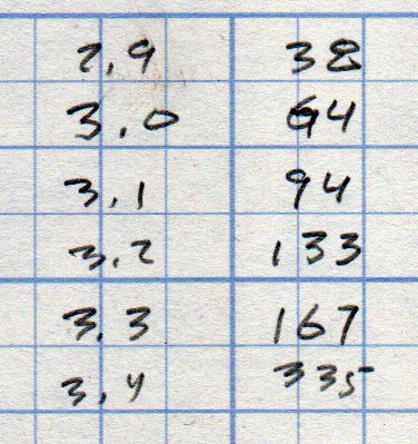
    Seven LEDs at 20 mA each = 140 mA, so the voltage booster must crank out slightly more than 3.2 V. They’re not the brightest white LEDs I’ve ever seen, but suffice for a small flashlight.

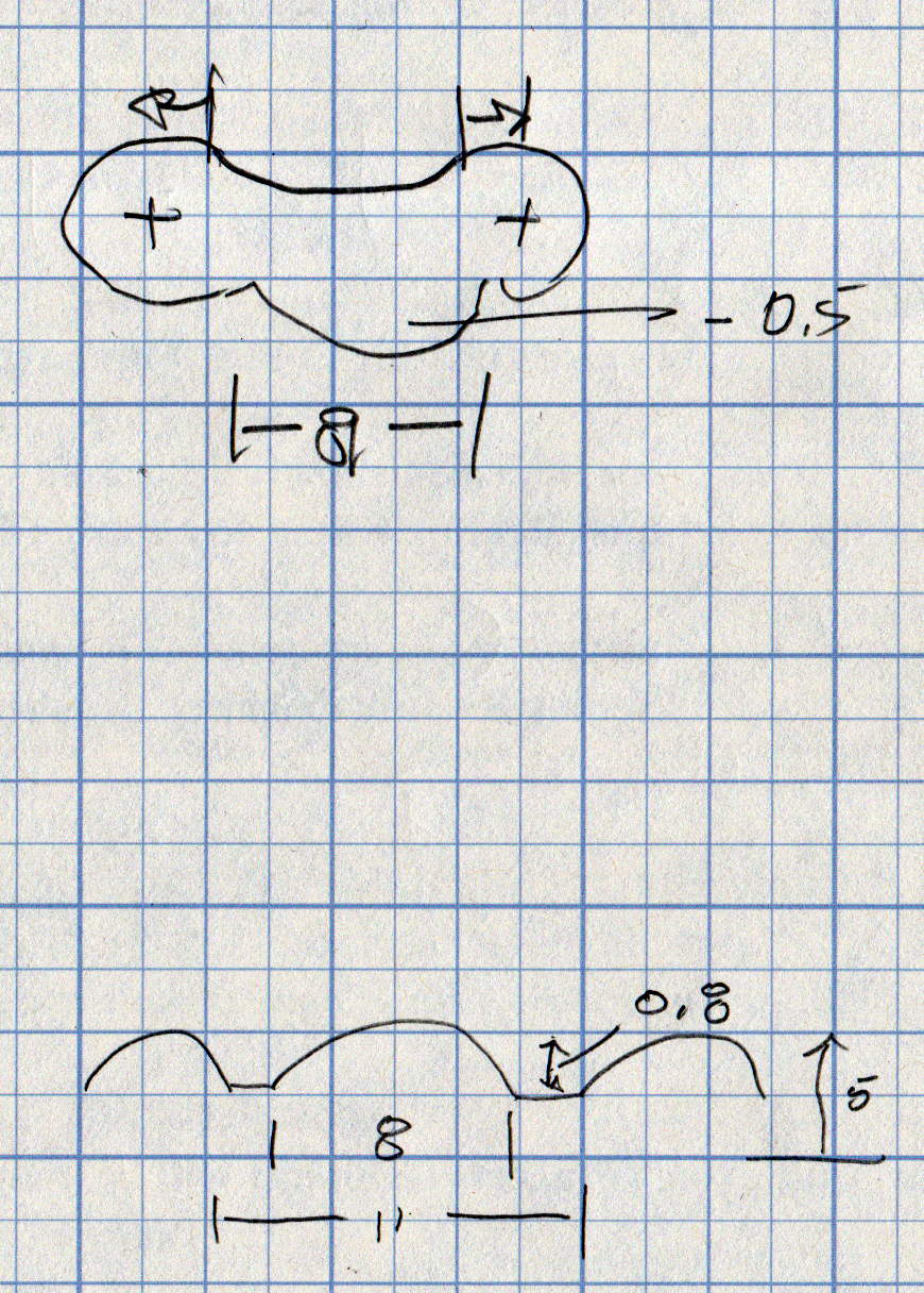
    A crude sketch of the PCB layout, with a completely incorrect schematic based on the mistaken assumption the SOT23-3 package was an NPN transistor:

    Small Sun flashlight - schematic doodle
    Small Sun flashlight – schematic doodle

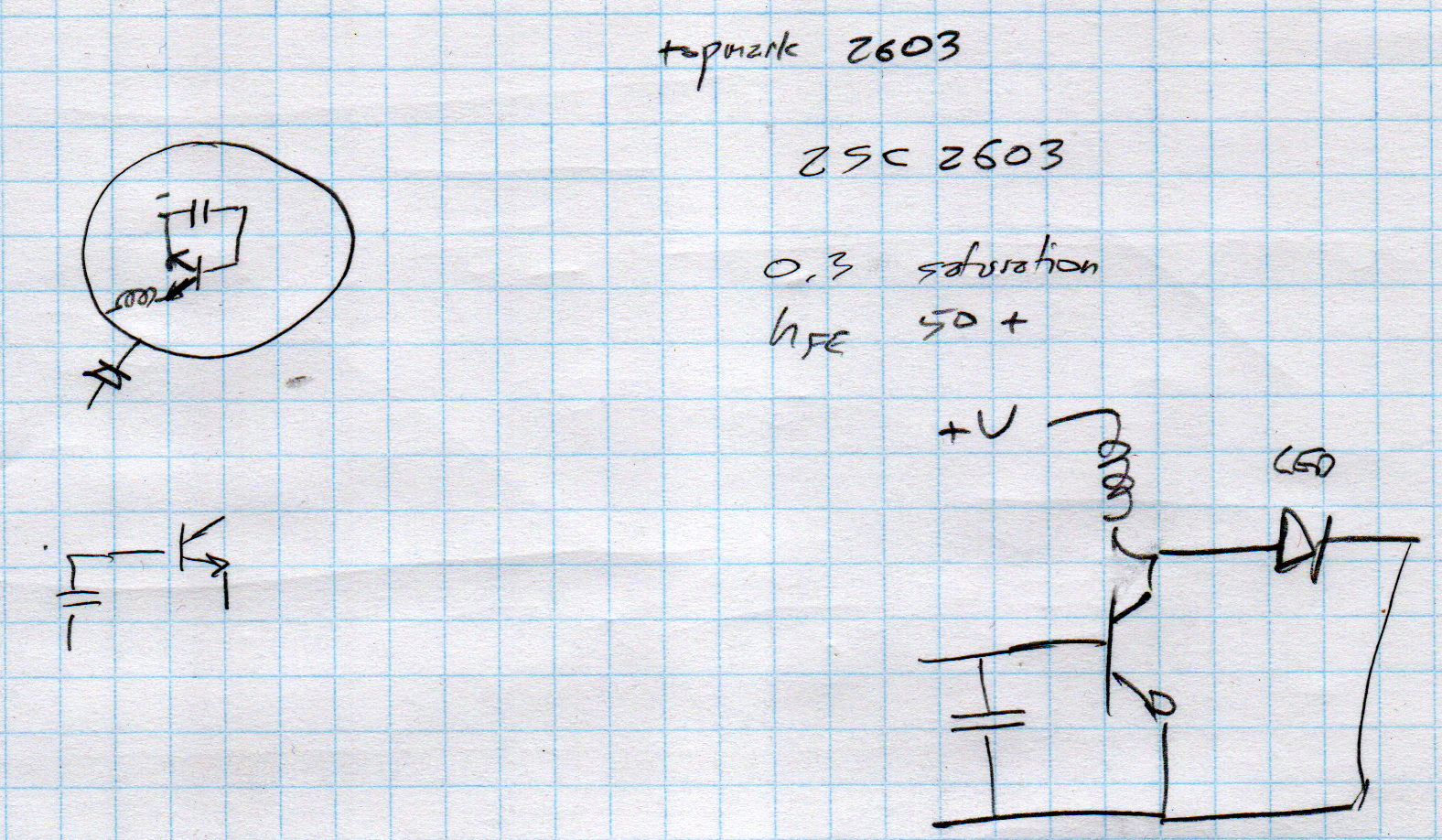
    Obviously, that’s just not ever going to oscillate, even if the 2603 topmark meant a 2SC2603 transistor, which it doesn’t.

    A bit more searching suggests it’s a stripped-down Semtech SC2603A boost converter, normally presented in a SOT23-6 package. If you order a few million of ’em, you can strip off three unused pins, do some internal rebonding, and (presumably) come out with an SOT23-3:

    Small Sun flashlight - correct schematic doodle
    Small Sun flashlight – correct schematic doodle

    That topology makes more sense!

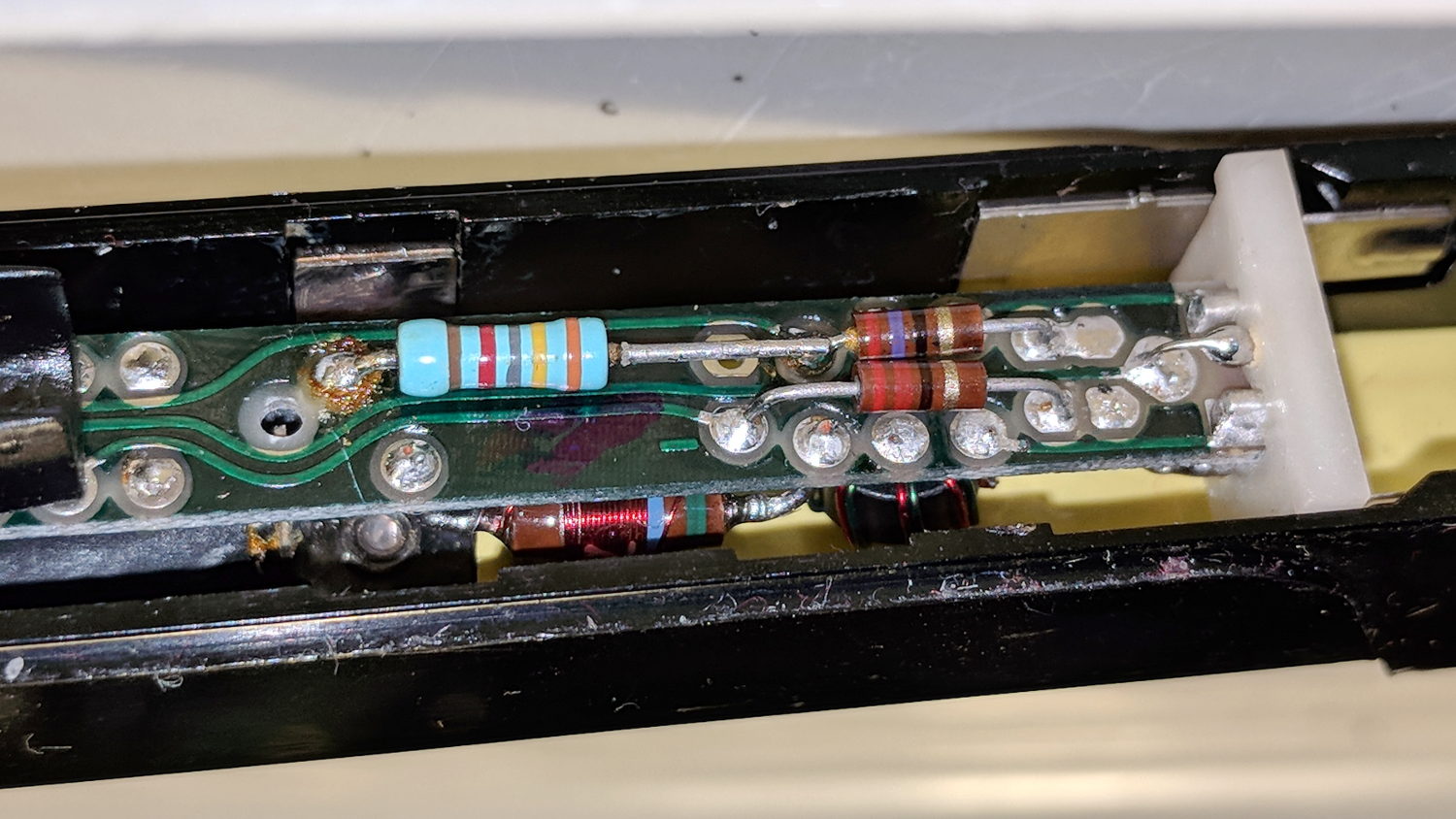
    Before going further, I had to rationalize the colors:

    Small Sun flashlight - rewired LED laser board
    Small Sun flashlight – rewired LED laser board

    Soldering longer leads to the PCB allows current & voltage measurements:

    Small Sun flashlight - LED current test
    Small Sun flashlight – LED current test

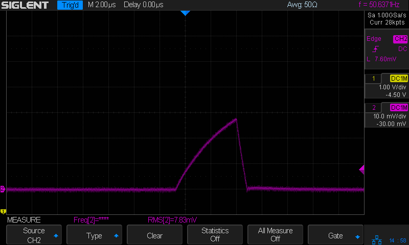
    With the LEDs and laser disconnected, the converter seems to be struggling to keep the capacitor charged:

    Small Sun flashlight - V boost I 200mA-div - idle
    Small Sun flashlight – V boost I 200mA-div – idle

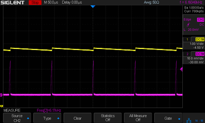
    Those purple spikes come from the current probe at 200 mA/div: maybe half an amp in 5 μs pulses at 6 kHz works out to a 15 mA average current, which is pretty close to the 11 mA I measured; it’s not obvious the Siglent SDM3045 meter was intended to handle such a tiny duty cycle.

    Obviously, the output capacitor is junk and, after removing it, the AADE L/C meter says NOT A CAPACITOR. Perhaps it never was one?

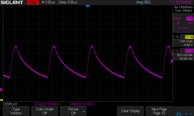
    Measuring the cap in the good (well, the other flashlight) suggests something around 100 nF, so I installed a random 110 nF cap from the stash. The current peaks are about the same size:

    Small Sun flashlight - I 200mA-div - 110nF cap
    Small Sun flashlight – I 200mA-div – 110nF cap

    The cap voltage (not shown) is now nearly constant and the 50 Hz PWM rate reduces the average battery current to 100-ish μA:

    Small Sun flashlight - I 200mA-div - color-grade - 110nF cap
    Small Sun flashlight – I 200mA-div – color-grade – 110nF cap

    Not great, but tolerable; a 1000 mA·h battery will go flat in a few months.

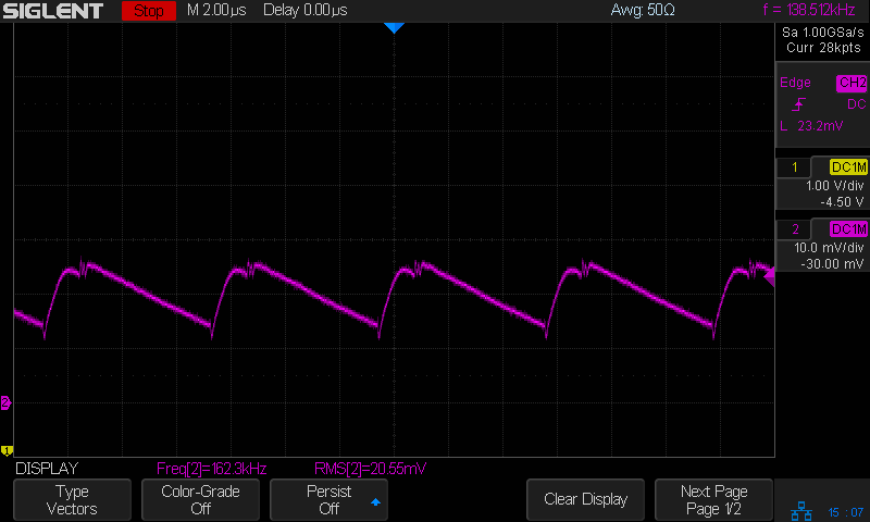
    The LED current runs a bit hotter than I expected:

    Small Sun flashlight - I 200mA-div - LED current - 110nF cap
    Small Sun flashlight – I 200mA-div – LED current – 110nF cap

    The bottom is about 200 mA and the average might be 350 to 400 mA.

    Compared with the other flashlight:

    Small Sun flashlight other - I 200mA-div - LED current
    Small Sun flashlight other – I 200mA-div – LED current

    So the cap is maybe a bit too small, but it likely doesn’t matter.

    Done!

  • Bathroom Sink Drain: Epoxy Touchup

    The glaring white ring around the drain comes from Magic Porcelain Chip Fix epoxy:

    Bathroom Sink Drain - Epoxy fill
    Bathroom Sink Drain – Epoxy fill

    What looks like a blob on the left side covers the missing chip, with the rest of the ring filled in to make it look like I knew what I was doing. The drain dried out while we were on vacation, having been scrubbed clean before we left, making for the best surface preparation I could provide.

    As it turns out, our resident iron bacteria took about a week to set up shop along the bottom of the ring, producing a pair of small rust-colored dots that will inevitably spread to encompass the whole thing. They’re endemic in the plumbing, impossible to kill off, and nothing more than an unsightly nuisance.

  • Amazon Basics AA Cells: Capacity

    Being that sort of bear, I (sometimes) note the date on cells when I change them, as with this notation on the AA alkaline cells in the Logitech trackball:

    Amazon Basics AA cell - mouse runtime
    Amazon Basics AA cell – mouse runtime

    These Amazon Basics AA cells lasted almost exactly two years, compared with 15 and 20 months from the previous two pairs of Duracell AAs. A few months one way or the other probably don’t mean much, but the Amazon cells aren’t complete duds.

    The new Amazon Basics cells have a gray paint job, so they’ve either changed suppliers or branding.

  • Rubber Soaker Hose Repair

    A soaker hose leaped under a descending garden fork and accumulated a nasty gash:

    Soaker Hose Splice - gashed
    Soaker Hose Splice – gashed

    Mary deployed a spare and continued the mission, while I pondered how to fix such an odd shape.

    For lack of anything smarter, I decided to put a form-fitting clamp around the hose, with silicone caulk buttered around the gash to (ideally) slow down any leakage:

    Soaker Hose Splice - Solid Model - Assembled
    Soaker Hose Splice – Solid Model – Assembled

    As usual, some doodling got the solid model started:

    Soaker Hose Splice - Dimension doodle 1
    Soaker Hose Splice – Dimension doodle 1

    A hose formed from chopped rubber doesn’t really have consistent dimensions, so I set up the model to spit out small test pieces:

    Soaker Hose Splice - Test Fit - Slic3r
    Soaker Hose Splice – Test Fit – Slic3r

    Lots and lots of test pieces:

    Soaker Hose Splice - test pieces
    Soaker Hose Splice – test pieces

    Each iteration produced a better fit, although the dimensions never really converged:

    Soaker Hose Splice - Dimension doodle 2
    Soaker Hose Splice – Dimension doodle 2

    The overall model looks about like you’d expect:

    Soaker Hose Splice - Complete - Slic3r
    Soaker Hose Splice – Complete – Slic3r

    The clamp must hold its shape around a hose carrying 100 psi (for real!) water, so I put 100 mil aluminum backing plates on either side. Were you doing this for real, you’d shape the plates with a CNC mill, but I just bandsawed them to about the right size and transfer-punched the hole positions:

    Soaker Hose Splice - plate transfer punch
    Soaker Hose Splice – plate transfer punch

    Some drill press action with a slightly oversize drill compensated for any misalignment and Mr Disk Sander rounded the corners to match the plastic block:

    Soaker Hose Splice - plate corner rounding
    Soaker Hose Splice – plate corner rounding

    A handful of stainless steel 8-32 screws holds the whole mess together:

    Soaker Hose Splice - installed
    Soaker Hose Splice – installed

    These hoses spend their lives at rest under a layer of mulch, so I’m ignoring the entire problem of stress relief at those sharp block edges. We’ll see how this plays out in real life, probably next year.

    I haven’t tested it under pressure, but it sure looks capable!

    The OpenSCAD source code as a GitHub Gist:

    // Rubber Soaker Hose Splice
    // Ed Nisley KE4ZNU July 2018
    Layout = "Build"; // Hose Block Show Build
    TestFit = false; // true to build test fit slice from center
    //- Extrusion parameters must match reality!
    ThreadThick = 0.25;
    ThreadWidth = 0.40;
    HoleWindage = 0.2;
    Protrusion = 0.1; // make holes end cleanly
    inch = 25.4;
    function IntegerMultiple(Size,Unit) = Unit * ceil(Size / Unit);
    //———-
    // Dimensions
    // Hose lies along X axis
    Hose = [200,27.0,12.0]; // X = longer than anything else
    Block = [80.0,50.0,4.0 + Hose.z]; // overall splice block size
    echo(str("Block: ",Block));
    Kerf = 0.1; // cut through middle to apply compression
    ID = 0;
    OD = 1;
    LENGTH = 2;
    // 8-32 stainless screws
    Screw = [4.1,8.0,3.0]; // OD = head LENGTH = head thickness
    Washer = [4.4,9.5,1.0];
    Nut = [4.1,9.7,6.0];
    CornerRadius = Washer[OD]/2;
    NumScrews = 3; // screws along each side of cable
    ScrewOC = [(Block.x – 2*CornerRadius) / (NumScrews – 1),
    Block.y – 2*CornerRadius,
    2*Block.z // ensure complete holes
    ];
    echo(str("Screw OC: x=",ScrewOC.x," y=",ScrewOC.y));
    //———————-
    // Useful routines
    module PolyCyl(Dia,Height,ForceSides=0) { // based on nophead's polyholes
    Sides = (ForceSides != 0) ? ForceSides : (ceil(Dia) + 2);
    FixDia = Dia / cos(180/Sides);
    cylinder(d=(FixDia + HoleWindage),h=Height,$fn=Sides);
    }
    // Hose shape
    // This includes magic numbers measured from reality
    module HoseProfile() {
    RimThick = 10.0; // outer sections
    RimOD = RimThick;
    RimFlatRecess = -0.7; // recess to front flat surface
    OuterOC = Hose.y – RimOD; // outer tube centers
    RecessM = 1.5; // back recess chord
    RecessC = OuterOC;
    RecessR = (pow(RecessM,2) + pow(RecessC,2)/4) / (2*RecessM);
    RidgeM = 1.0; // front ridge chord
    RidgeC = 8.0;
    RidgeR = (pow(RidgeM,2) + pow(RidgeC,2)/4) / (2*RidgeM);
    NumSides = 12*4;
    rotate([0,-90,0])
    translate([0,0,-Hose.x/2])
    linear_extrude(height=Hose.x,convexity=4)
    difference() {
    union() {
    for (j=[-1,1]) // outer channels
    translate([0,j*OuterOC/2])
    circle(d=RimOD,$fn=NumSides);
    translate([-RimOD/4,0]) // rear flat fill
    square([RimOD/2,OuterOC],center=true);
    translate([(RimOD/4 + RimFlatRecess),0]) // front flat fill
    square([RimOD/2,OuterOC],center=true);
    intersection() {
    translate([Hose.z/2,0])
    square([Hose.z,OuterOC],center=true);
    translate([-RidgeR + RimOD/2 + RimFlatRecess + RidgeM,0])
    circle(r=RidgeR,$fn=NumSides);
    }
    }
    translate([-(RecessR + RimOD/2 – RecessM),0])
    circle(r=RecessR,$fn=2*NumSides);
    }
    }
    // Outside shape of splice Block
    // Z centered on hose rim circles, not overall thickness through center ridge
    module SpliceBlock() {
    difference() {
    hull()
    for (i=[-1,1], j=[-1,1]) // rounded block
    translate([i*(Block.x/2 – CornerRadius),j*(Block.y/2 – CornerRadius),-Block.z/2])
    cylinder(r=CornerRadius,h=Block.z,$fn=4*8);
    for (i = [0:NumScrews – 1], j=[-1,1]) // screw holes
    translate([-(Block.x/2 – CornerRadius) + i*ScrewOC.x,
    j*ScrewOC.y/2,
    -(Block.z/2 + Protrusion)])
    PolyCyl(Screw[ID],Block.z + 2*Protrusion,6);
    cube([2*Block.x,2*Block.y,Kerf],center=true); // slice through center
    }
    }
    // Splice block less hose
    module ShapedBlock() {
    difference() {
    SpliceBlock();
    HoseProfile();
    }
    }
    //———-
    // Build them
    if (Layout == "Hose")
    HoseProfile();
    if (Layout == "Block")
    SpliceBlock();
    if (Layout == "Bottom")
    BottomPlate();
    if (Layout == "Top")
    TopPlate();
    if (Layout == "Show") {
    difference() {
    SpliceBlock();
    HoseProfile();
    }
    color("Green",0.25)
    HoseProfile();
    }
    if (Layout == "Build") {
    SliceOffset = TestFit && !NumScrews%2 ? ScrewOC.x/2 : 0;
    intersection() {
    translate([SliceOffset,0,Block.z/4])
    if (TestFit)
    cube([ScrewOC.x/2,4*Block.y,Block.z/2],center=true);
    else
    cube([4*Block.x,4*Block.y,Block.z/2],center=true);
    union() {
    translate([0,0.6*Block.y,Block.z/2])
    ShapedBlock();
    translate([0,-0.6*Block.y,Block.z/2])
    rotate([0,180,0])
    ShapedBlock();
    }
    }
    }
  • Tour Easy Front Fender Clip: Longer and Stronger

    We negotiated the Belmar Bridge connection stairway from the Allegheny River Trail to the Sandy Creek trail:

    Belmar Bridge Stairs - Overview
    Belmar Bridge Stairs – Overview

    We’re maneuvering Mary’s bike, but you get the general idea. Our bikes aren’t built for stairways, particularly ones with low overheads:

    Belmar Bridge Stairs - Low Overhead
    Belmar Bridge Stairs – Low Overhead

    The front fender clip on my Tour Easy snapped (at the expected spots) when the mudflap snagged on one of the angles:

    Belmar Bridge Stairs - First Turn
    Belmar Bridge Stairs – First Turn

    For some inexplicable reason, I didn’t have a roll of duct tape in my packs, so the temporary repair required a strip of tape from a battery pack, two snippets of hook-and-loop tape, and considerable muttering:

    Tour Easy front fender clip - expedient repair
    Tour Easy front fender clip – expedient repair

    It was good for two dozen more miles to the end of our vacation, so I’d say that was Good Enough.

    The new version has holes in the ferrules ten stay diameters deep, instead of six, which might eliminate the need for heatstink tubing. I added a small hole at the joint between the curved hooks and the ferrules to force more plastic into those spots:

    Front Fender Clip - Slic3r
    Front Fender Clip – Slic3r

    I also bent the hanger extension to put the fender’s neutral position closer to the wheel.

    We’ll see how long this one lasts. By now, I now have black double-sticky foam tape!

    The OpenSCAD source code as a GitHub Gist:

    // Tour Easy front fender clip
    // Ed Nisley KE4ZNU July 2017
    Layout = "Build"; // Build Profile Ferrule Clip
    //- Extrusion parameters must match reality!
    ThreadThick = 0.25;
    ThreadWidth = 0.40;
    HoleWindage = 0.2;
    Protrusion = 0.1; // make holes end cleanly
    inch = 25.4;
    function IntegerMultiple(Size,Unit) = Unit * ceil(Size / Unit);
    //———————-
    // Dimensions
    // special case: fender is exactly half a circle!
    FenderC = 51.0; // fender outside width = chord
    FenderM = 21.0; // height of chord
    FenderR = (pow(FenderM,2) + pow(FenderC,2)/4) / (2 * FenderM); // radius
    echo(str("Fender radius: ", FenderR));
    FenderD = 2*FenderR;
    FenderA = 2 * asin(FenderC / (2*FenderR));
    echo(str(" … Arc: ",FenderA," deg"));
    FenderThick = 2.5; // fender thickness, assume dia of edge
    ClipHeight = 15.0; // top to bottom, ignoring rakish tilt
    ClipThick = IntegerMultiple(2.5,ThreadWidth); // thickness of clip around fender
    ClipD = FenderD; // ID of clip against fender
    ClipSides = 4 * 8; // polygon sides around clip circle
    BendReliefD = 2.5; // bend arch diameter
    BendReliefA = 2/3 * FenderA/2; // … angle from dead ahead
    BendReliefCut = 1.5; // factor to thin outside of bend
    ID = 0;
    OD = 1;
    LENGTH = 2;
    StayDia = 3.3; // fender stay rod diameter
    StayOffset = 15.0; // stay-to-fender distance
    StayPitch = -5; // angle from stay to fender arch
    DropoutSpace = 120; // stay spacing at wheel hub
    StayLength = 235; // stay length: hub to fender
    StaySplay = asin((DropoutSpace – FenderC)/(2*StayLength)); // outward angle to hub
    echo(str(" … Pitch: ",StayPitch," deg"));
    echo(str(" … Splay: ",StaySplay," deg"));
    FerruleSides = 2*4;
    Ferrule = [StayDia,3*FenderThick/cos(180/FerruleSides),10*StayDia + StayOffset]; // ID = stay rod OD
    FerruleHoleD = 0.1; // small hole to create solid plastic at ferrule joint
    //———————-
    // Useful routines
    module PolyCyl(Dia,Height,ForceSides=0) { // based on nophead's polyholes
    Sides = (ForceSides != 0) ? ForceSides : (ceil(Dia) + 2);
    FixDia = Dia / cos(180/Sides);
    cylinder(r=(FixDia + HoleWindage)/2,
    h=Height,
    $fn=Sides);
    }
    //———————-
    // Clip profile around fender
    // Centered on fender arc
    module Profile(HeightScale = 1) {
    linear_extrude(height=HeightScale*ClipHeight,convexity=5) {
    difference() {
    offset(r=ClipThick) // outside of clip
    union() {
    circle(d=ClipD,$fn=ClipSides);
    for (i=[-1,1])
    rotate(i*BendReliefA) {
    translate([ClipD/2 + BendReliefD/2,0,0])
    circle(d=BendReliefD,$fn=6);
    }
    }
    union() { // inside of clip
    circle(d=ClipD,$fn=ClipSides);
    for (i=[-1,1])
    rotate(i*BendReliefA) {
    translate([ClipD/2 + BendReliefCut*BendReliefD/2,0,0])
    circle(d=BendReliefD/cos(180/6),$fn=6);
    translate([ClipD/2,0,0])
    square([BendReliefCut*BendReliefD,BendReliefD],center=true);
    }
    }
    translate([(FenderR – FenderM – FenderD/2),0]) // trim ends
    square([FenderD,2*FenderD],center=true);
    }
    for (a=[-1,1]) // hooks around fender
    rotate(a*(FenderA/2))
    translate([FenderR – FenderThick/2,0]) {
    difference() {
    rotate(1*180/12)
    circle(d=FenderThick + 2*ClipThick,$fn=12);
    rotate(1*180/8)
    circle(d=FenderThick,$fn=8);
    rotate(a * -90)
    translate([0,-2*FenderThick,0])
    square(4*FenderThick,center=false);
    }
    }
    }
    }
    //———————-
    // Ferrule body
    module FerruleBody() {
    translate([0,0,Ferrule[OD]/2 * cos(180/FerruleSides)])
    rotate([0,-90,0]) rotate(180/FerruleSides)
    difference() {
    cylinder(d=Ferrule[OD],h=Ferrule[LENGTH],$fn=FerruleSides,center=false);
    translate([0,0,StayOffset + Protrusion])
    PolyCyl(Ferrule[ID],Ferrule[LENGTH] – StayOffset + Protrusion,FerruleSides);
    }
    }
    //———————-
    // Generate entire clip at mounting angle
    module FenderClip() {
    difference() {
    union() {
    translate([FenderR,0,0])
    difference() { // angle and trim clip
    rotate([0,StayPitch,0])
    translate([-(FenderR + ClipThick),0,0])
    Profile(2); // scale upward for trimming
    translate([0,0,-ClipHeight]) // trim bottom
    cube(2*[FenderD,FenderD,ClipHeight],center=true);
    translate([0,0,ClipHeight*cos(StayPitch)+ClipHeight]) // trim top
    cube(2*[FenderD,FenderD,ClipHeight],center=true);
    }
    for (j = [-1,1]) // place ferrules
    translate([Ferrule[OD]*sin(StayPitch) + (Ferrule[OD]/2)*sin(StaySplay),j*(FenderR – FenderThick/2),0])
    rotate(-j*StaySplay)
    FerruleBody();
    }
    for (i=[-1,1]) // punch stiffening holes
    translate([FenderThick/2,-i*(FenderR – FenderThick/2),Ferrule[OD]/2])
    rotate([0,-90,i*StaySplay])
    PolyCyl(FerruleHoleD,Ferrule[OD],FerruleSides);
    }
    }
    //———————-
    // Build it
    if (Layout == "Profile") {
    Profile();
    }
    if (Layout == "Ferrule") {
    FerruleBody();
    }
    if (Layout == "Clip") {
    FenderClip();
    }
    if (Layout == "Build") {
    FenderClip();
    }

    As a bonus for paging all the way to the end, here’s the descent on the same stairway:

    Belmar Bridge Stairs - Descent
    Belmar Bridge Stairs – Descent

    No, I wasn’t even tempted …

  • Tek A6302 Current Probe: Offset Resistor Tweakage

    A package deal of two Tektronix A6302 current probes arrived from eBay, with one probe having a small crack across its case (shown in the description and bought accordingly).

    The other probe worked fine and was quite clean inside:

    A6302 B055461 - major sections
    A6302 B055461 – major sections

    The cracked one couldn’t be balanced, with the twiddlepot on the AM503 amp unable to bring the signal down to 0 V from a positive offset on any of the ranges.

    The current transformer might have suffered some stress on the upper-left corner of the main part (in the probe body), but it doesn’t have any obvious damage:

    A6302 B032444 - ball - current transformer in place
    A6302 B032444 – ball – current transformer in place

    The small ball to the left of the transfomer lid provides the slide detent; it’s an ordinary 3/32 = 0.094 inch bearing. Which, as it happens, is a Good Thing, because there’s another one exactly like it somewhere in the litter under the Electronics Workbench.

    Protip: follow the disassembly procedure in the instruction manual and do it over a towel or, at least, a shallow dish. You have been warned.

    Extracting the transformer from the body revealed a numeric value I didn’t recognize at the time:

    A6302 B032444 - current transformer
    A6302 B032444 – current transformer

    The top slide contacts looked awful, but they’re actually covered in semi-dried contact grease and cleaned up easily:

    A6302 B032444 - slide contacts
    A6302 B032444 – slide contacts

    Swapping the “bad” transformer into the P6302 probe I got a while ago showed it wouldn’t balance, either, but the offset was far off into negative voltages. Putting the “good” transformer into the “bad” probe produced a similar too-positive offset. Conclusion: the transformer was probably good and Something Else was wrong.

    Spending more time with the manuals produced this hint in the AM503 Amplifier circuit description:

    AM503 manual - Hall offset - probe resistor selection
    AM503 manual – Hall offset – probe resistor selection

    Fortunately, the AM503 probe connector has pin labels:

    Tek AM503 Amplifier - Probe Connector - pin ID
    Tek AM503 Amplifier – Probe Connector – pin ID

    Note the absence of pins G and I, probably to eliminate any confusion with “ground” and “one”, respectively.

    Continuity checking reveals the left end of the 34.8 kΩ resistor connects to pin H:

    A6302 B032444 - PCB 34.8k offset R
    A6302 B032444 – PCB 34.8k offset R

    Huh. Even a blind pig occasionally finds a truffle: where have we seen that value before? Apparently Tek measured each transformer / Hall sensor and wrote the appropriate offset resistor value exactly where it’d do the most good.

    Although I don’t pretend to know why the transformer offset has changed, if Tek can select a resistor to correct the offset, so can I:

    A6302 B032444 - PCB - tweaked 82k offset R
    A6302 B032444 – PCB – tweaked 82k offset R

    The 82 kΩ value roughly centers the offset twiddlepot span around 0 V; it’s the result of a binary search through the resistor drawers, rather than a complex calculation.

    With the resistor in place and the probe reassembled in reverse order, everything works the way it should:

    Tek A6302 - 82k ohm offset - 50 mA
    Tek A6302 – 82k ohm offset – 50 mA

    The lower trace is a square wave from the scope’s arb waveform generator into a (likely counterfeit) Fotek DC-DC solid-state relay, with the bench supply dialed to 5.7 V to put 5 V across a hulking 100 Ω power resistor, thus 50 mA through the probe. The purple trace comes from the repaired probe, with the other one turned off for pedagogic purposes:

    Tek A6302 Calibration Setup
    Tek A6302 Calibration Setup

    That wasn’t easy, but seems to solve the problem.

    Dang, I loves me some good Tek current probe action …


  • Rt 376 at Red Oaks Mill: Re-repaving

    For unknown reasons, NYS DOT milled away some of the newly laid asphalt north of Red Oaks Mill:

    Rt 376 Red Oaks Mill - New Pavement Milling
    Rt 376 Red Oaks Mill – New Pavement Milling

    Then laid it down again:

    Rt 376 Red Oaks Mill - New Pavement - 2018-06-14
    Rt 376 Red Oaks Mill – New Pavement – 2018-06-14

    As far as we can tell, there’s absolutely no difference, other than the opportunity for a huge longitudinal crack between the shoulder and the travel lane.

    My guess: the contractor shorted them an inch of asphalt, got caught, and had to do it over again.

    It’s only NYS Bike Route 9, so you can’t expect much in the way of bicycle-friendly design or build quality.