Ed Nisley's Blog: Shop notes, electronics, firmware, machinery, 3D printing, laser cuttery, and curiosities. Contents: 100% human thinking, 0% AI slop.
The orange curve is the last surviving (“least dead”) Wasabi battery from the 2017-08 batch and the dark green curve just above it is another DOT-01 from 2019-02. The problem is not so much their reduced capacity, but their grossly reduced voltage-under-load that triggers a premature camera shutdown.
The Batmax batteries measure better than the craptastic Wasabi batteries, worse than the STK batteries, and should survive the next year of riding. As before, I have zero belief that Amazon would send me a “genuine” Sony NP-BX1 battery, even at six times the nominal price, nor that it would perform six times better.
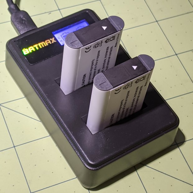
Batmax is one of many randomly named Amazon Marketplace sellers offering seemingly identical NP-BX1 batteries: Newmowa, Miady, Powerextra, Pickle Power, LP, Enegon, and so forth. Mysteriously, it’s always cheaper to get a handful of batteries and a charger, rather than just the batteries, so I now have a two-socket USB charger:
Batmax NP-BX1 – USB dual charger
Despite the “5 V 2 A – 10 W” and “4.2 V 0.6 A – 5 W” label on the back, charging a pair of batteries after a ride started at 700 mA from a USB 3.0 port. The charger makes no claims about USB 3 compliance, so I’d expect it to top out around 1 A from a generously specified port.
Our CVS blood pressure meter (a relabeled Microlife unit) ran its pump for a few seconds this morning, gave up, and spat out Err 3, which translates into “Inflation of the cuff takes too long”. Not surprising, as the motor wasn’t running.
The AA alkaline cell quartet has plenty of mojo and no corrosion, but the motor doesn’t even turn over. The display is fine and the pressure release valve clicks, so it’s not completely dead.
This unit is sufficiently old to have the compelling advantage of transferring data through a USB (mini-B) connection, rather than a Bluetooth link through some sketchy Internet cloudy Android app, so it’s worth at least a look inside. Four screws and some internal snaps along the sides hold the case together; it’s a surprisingly easy teardown.
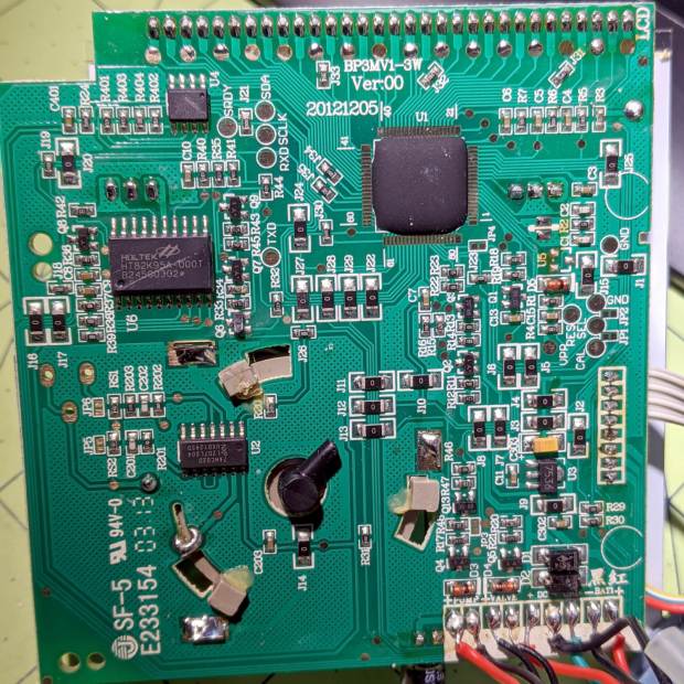
The business side of the PCB looks good:
CVS Blood Pressure Monitor – PCB
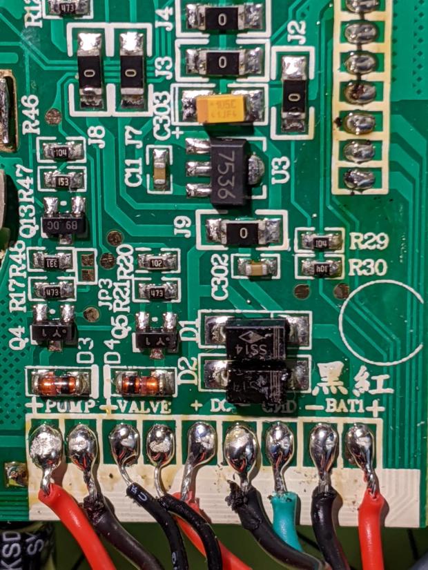
The various wires and solder joints for the “high current” parts look OK, although the wires likely don’t go all the way through the PCB:
CVS Blood Pressure Monitor – PCB detail
Q4 and Q5 look like they switch the compressor pump motor and pressure-release valve. D3 and D4 should tamp down the inductive energy, but they look like they’re in series with the outputs. Yes, the Valve wires are both black.
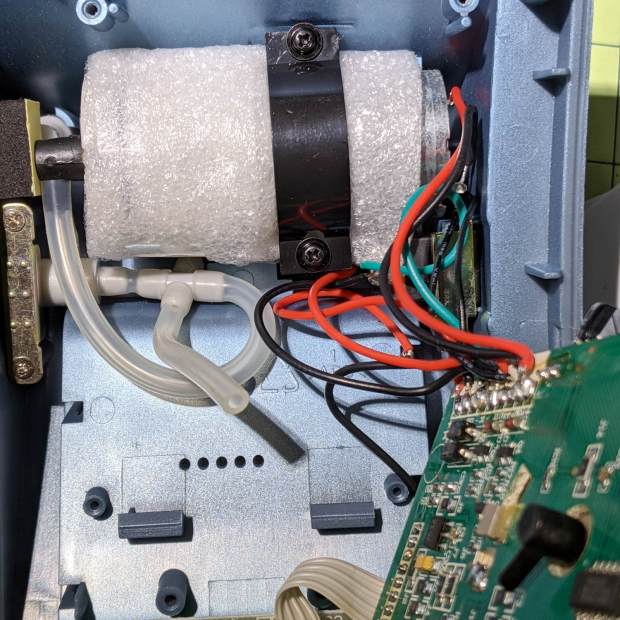
The motor has a foam vibration isolation wrap, which is a nice touch. Although you can’t see them well, all its wires & solder joints look like they’re in good shape:
CVS Blood Pressure Monitor – pump
The hose sticking out toward you plugs into the black right-angle fitting in the lower right corner of the picture. It’d help to have smaller fingers than mine, but I managed to get the hose off and on the fitting with only minor muttering.
Seeing nothing obviously wrong, I installed the same batteries, poked the switch to start a measurement, and the motor ran fine. Of course, the measurement failed because the cuff & pressure sensor weren’t connected.
Connect the hose, plug in the cuff & wrap it around my arm, poke the button, and everything works fine.
Reassemble everything and it still works fine.
I still think there’s a bad wire or solder joint in there somewhere, so this delightful “repair” can’t possibly last very long …
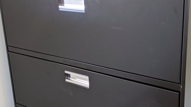
You’d hope the original owner would tape a key inside each file cabinet before donating it to charity; ours arrived unlocked and without keys. Fortunately, eBay sellers have All The Keys and I ordered replacement keys for each cabinet.
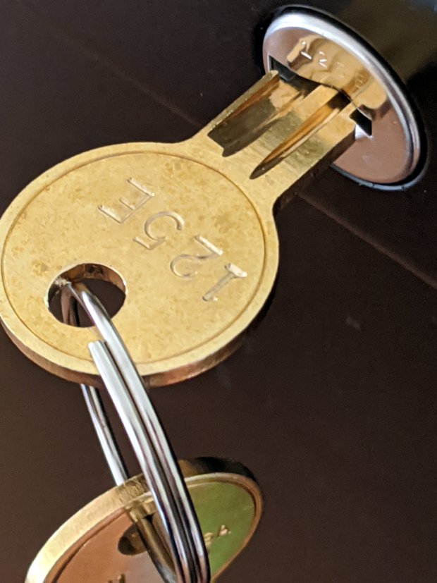
One pair of new keys fit into their lock, but the shoulder didn’t seat properly and the key didn’t turn:
HON Lateral File – 125E key insertion
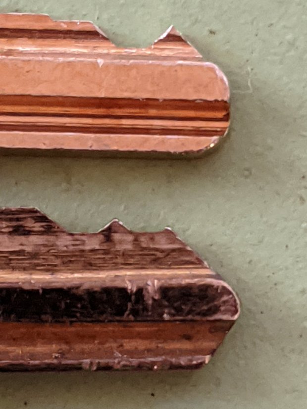
Compared with a key for the other cabinet (on the bottom), it seems the tip profile wasn’t quite the same:
HON Lateral File – 125E key tip
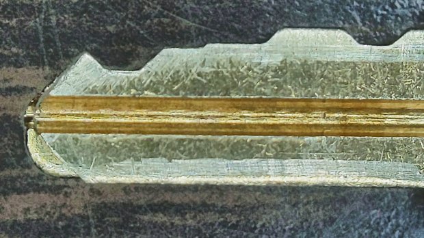
Perhaps the underside of the tip hadn’t been cut? Stacking the two keys makes it even more obvious:
Key 125E tip shaping – vs Key 101E
The eBay seller suggested the lock cores have changed over the years, as other (unaltered) keys fit current cabinet locks. Perhaps HON used fussy high-quality lock cores back in 2004 when they built these cabinets.
I gingerly filed the 125E key’s tip to match the 101E key and, after several iterations, the shoulder seated firmly in the lock and the core turned smoothly. Flushed with success, I marked the other key of the pair, filed to the mark, and it worked on the first try.
Mary doesn’t plan to store any secret fabrics in her new cabinets, but now I can declare victory and move on.
After sliding the HON Lateral File Cabinet shelf into place and installing the bumpers, it seemed rather loose and floppy. Comparing the situation with the other file cabinet showed it had a missing glide button in the rear and two missing slides at the front.
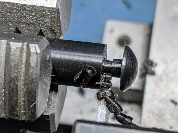
A replacement button emerged from the end of a Delrin rod:
HON Lateral File – shelf button – parting off
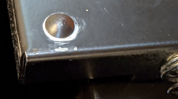
The original buttons had an expanding stem, which is easy to do with an injection-molded part. I opted for simple adhesive, with enough of a blob underneath the shelf to (presumably) lock it in place forevermore:
HON Lateral File – shelf button – installed
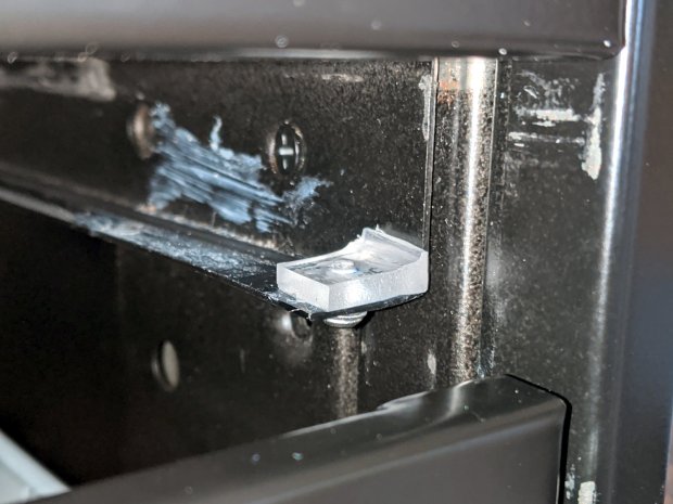
The slides required an iterative design technique (pronounced “fumbling around”), because nothing on either side remained square / plumb / true / unbent. I hacked the first version from scrap acrylic, broke off anything that didn’t fit, and got better measurements from what remained:
HON Lateral File – shelf front guide – size test
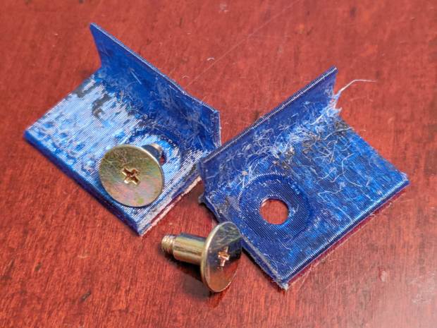
With those measurements in hand, the second version used a pair of weird flat-head shoulder screws (probably from a hard drive) to anchor 3D printed angle brackets into the frame:
HON Lateral File – shelf slides – version 2
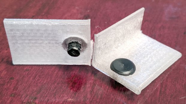
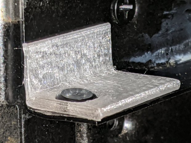
Those worked reasonably well, but PETG doesn’t produce a nice sliding surface, so the final version has flat-head Delrin studs in slightly tweaked brackets:
HON Lateral File – shelf slides – version 3
As with the buttons in the back, the original slides had expanding studs holding them in place, but glue works fine here, too:
HON Lateral File – shelf slides – version 3 – installed
The button isn’t quite square to the surface and the slide isn’t quite flush with the bent metal in the frame, but it’s Good Enough™ for a shelf that won’t get lots of mileage.
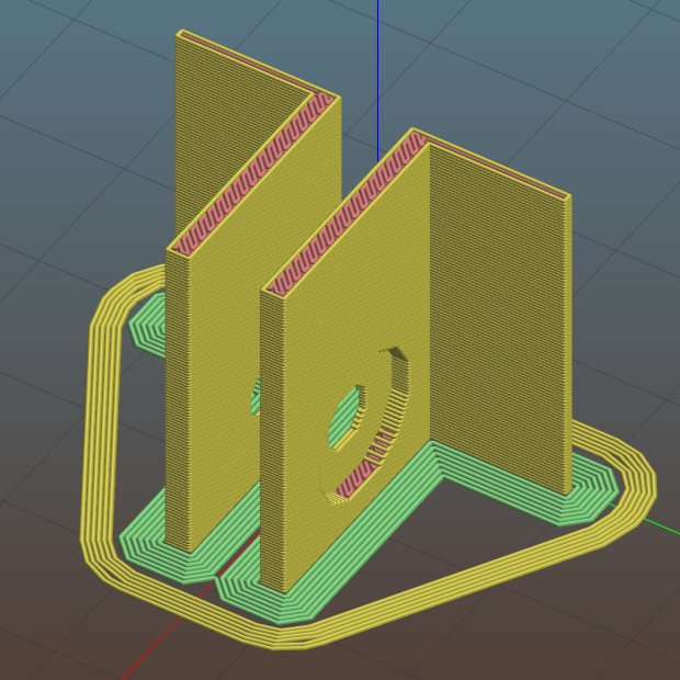
For reference, the brackets should print vertically to wrap the plastic threads around the upright for better strength:
HON Lateral File Shelf Slide – Slic3r
If you did it the obvious way, the upright side would break right off at the first insult from the hulking shelf, although they’re basically a solid chip of plastic, with a little infill inside the bottom slab.
While I was at it, I pulled the springs to make them a bit longer, so they touch the back of the frame when the shelf is half an inch behind the front face of the drawers. A firm push and those Delrin contact points let the shelf pop out an inch or so, with plenty of room for fingers underneath the front edge.
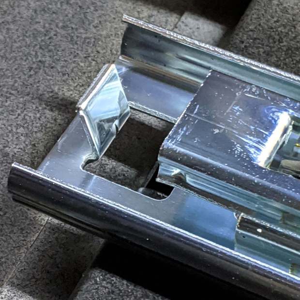
Some drawer slide stops near the back needed attention, too:
HON Lateral File – slide stop bumper – bent
I cannot imagine how hard somebody slammed the drawers, because bending the stops back to a right angle required a Vise-Grip and some muttering:
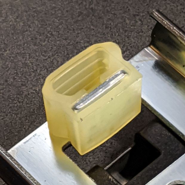
HON Lateral File – slide stop bumper
Oddly, the cushiony hollow side faces away from the drawer, toward the back of the frame, because putting it forward holds the drawer front proud of the front frame face. Maybe HON cost-reduced the steel slides by making them just slightly shorter and using the same bumpers?
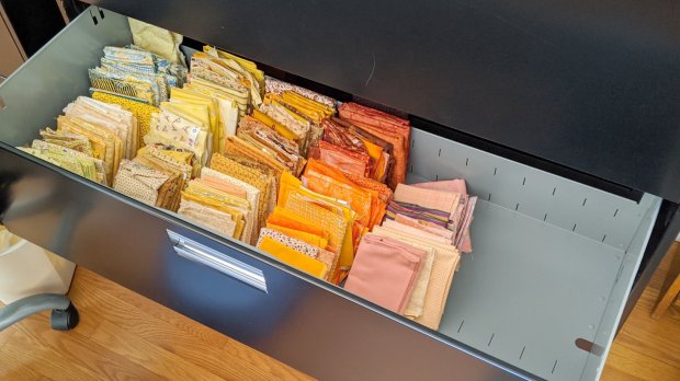
The drawers have begun filling up from boxes scattered around the house:
HON Lateral File – fabric stash
That’s the “orange” part of Mary’s collection, now with plenty of room to grow!
This file contains hidden or bidirectional Unicode text that may be interpreted or compiled differently than what appears below. To review, open the file in an editor that reveals hidden Unicode characters.
Learn more about bidirectional Unicode characters
Somewhat to our surprise, our “new” HON Lateral File Cabinets include a pop-out shelf:
HON Lateral File – shelf – closed
The trick: push the bar inward against fairly stiff spring pressure, release it suddenly, watch it pop out maybe half an inch, get some fingers under the front edge, then pull it outward:
HON Lateral File – shelf – extended
Obviously, opening the drawer above the shelf will sweep whatever you put there onto the floor and opening the drawer below seems futile. I suppose it produced a bullet item on the features list.
Note that the topmost “drawer” is also called a “shelf”, because the front cover slides up-and-inward to reveal the contents. Should you stand eight feet tall, you might be able to look down on that shelf, but we mere mortals barely see its contents at eye level.
Dismantling the cabinets preparatory to deep cleaning revealed a pair of rubber bumpers along the rear edge of the shelf:
HON Lateral File – shelf bumper – installed
The slightly angled front side of the bumper (on the right) collides with a crossbar below the drawer just above it, preventing you from pulling the shelf entirely out of the cabinet.
Remove the bumper by pressing down and rearward (to the left), shoving the protruding lip into the slot with a thumb / screwdriver, then pull it upward through the slot:
HON Lateral File – shelf bumper – removed
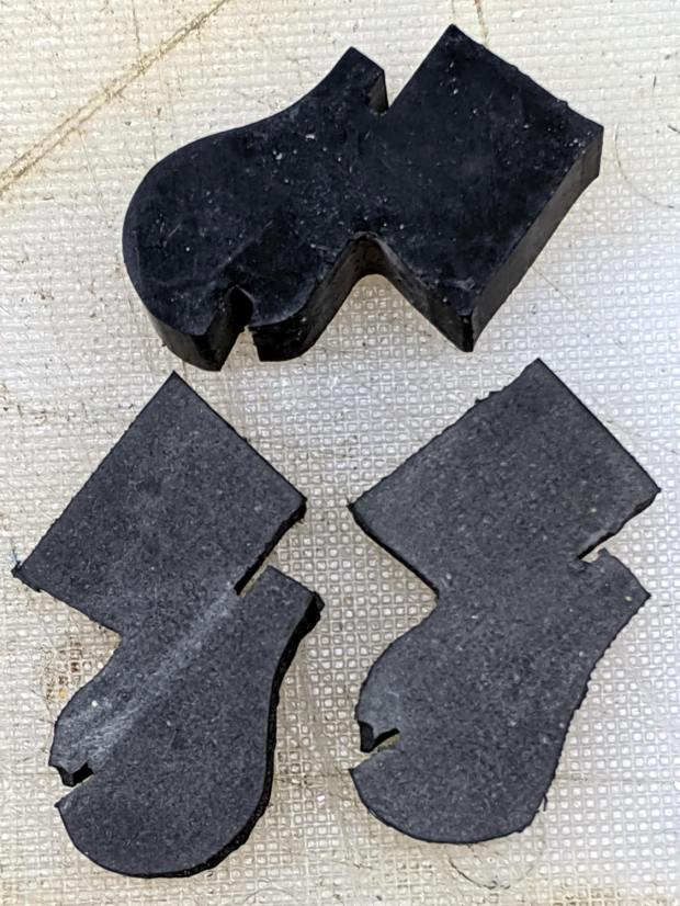
The second cabinet had only one bumper, so I traced it twice onto a rubber sheet half as thick as the OEM bumper, bandsawed the shapes, and introduced them to Mr Belt Sander for cleanup:
HON Lateral File – replacement shelf bumper
Jammed side-by-side into the slot, they’ll serve the purpose:
HON Lateral File – replacement shelf bumper – installed
As with the replacement foot on the first cabinet, they’re not the prettiest things you’ve ever seen, but Mary doesn’t expect to use the shelf and they’ll never actually bump into anything.
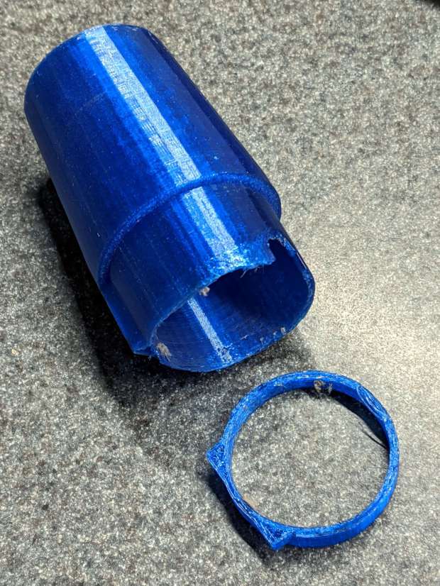
Even the Pixel phone’s HDR image processing has trouble dealing with dark gray objects on a black background in dim light …
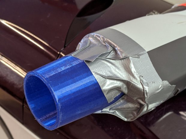
A better fix required a few minutes of OpenSCAD tweakage and a few hours of hands-off build time:
Refrigerator Coil Wand Adapter – Slic3r preview
The fitting ID is now 2 mm smaller, the 3D honeycomb infill is 25%, and (contrary to the picture) it now has 4 perimeter threads. It’s a two-line change from the last time:
We bought the best-looking (pronounced “least bashed”) pair of hulking five-drawer industrial-strength HON Brigade Lateral File Cabinets from the local ReStore outlet’s assortment for Mary’s quilting fabric stash. They came with a steep discount, barely fit inside the Forester, caused minor interior trim damage, and should organize her entire stash.
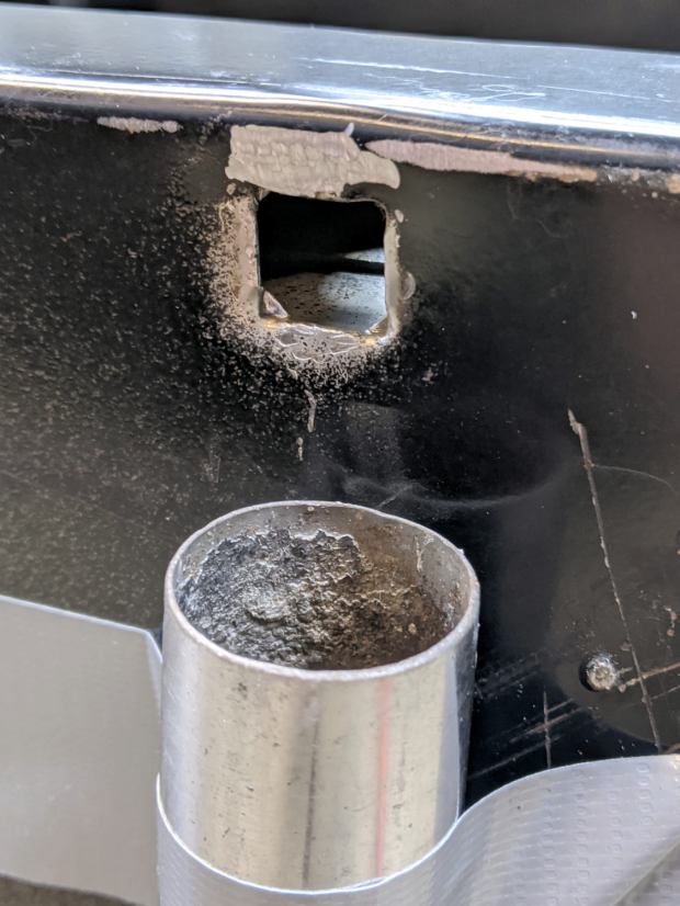
One cabinet lost a foot nut at some point in its 16 year history:
HON Lateral File – foot hole – weld nugget filed
The surviving foot nuts sported two weld nuggets apiece:
HON Lateral File – OEM front foot
The hole had the remains of one nugget at the top left and looks like a manufacturing defect to me. Of course, we’re (at least) the second owners and the usual lifetime warranty no longer applies.
I can fix that.
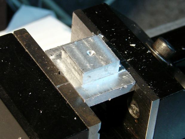
Bandsaw a 1×¾ inch rectangle from 3/8 inch aluminum plate to match the surviving foot nut (which is steel, but aluminum will suffice for our needs). Break the edges, clamp in the Sherline, and mill a square protrusion to match the square-ish hole:
HON Lateral File – square nut – rough cut
Drill a 17/64 inch hole (looser than the nominal F drill, because I’m a sissy) for a flat-head bolt from the Drawer o’ 3/8-16 Bolts, tap, and clean up.
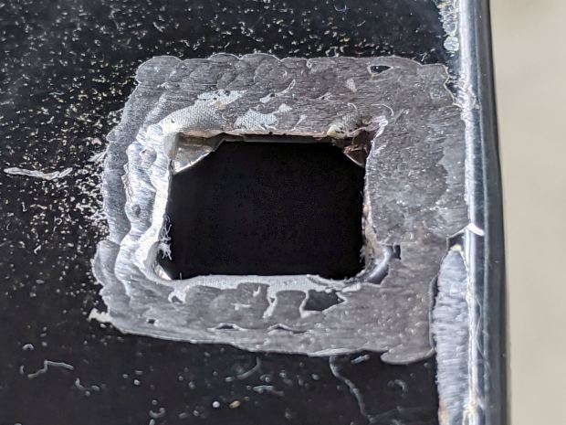
A trial fit showed the nugget had to go before the nut would come even close to fitting flat into the hole:
HON Lateral File – foot hole – grinding
The sheet metal around the hole had absorbed at least one mighty blow pushing the entire surface inward behind the front edge. To compensate, recess the nut’s front edge and slope the sides with a Dremel wheel to let the bottom face sit level:
HON Lateral File – square nut – taper grinding
Another trial fit showed the need for more recess:
HON Lateral File – square nut – deeper cut
Another spate of grinding made it sit mostly level on the decidedly non-level surface around the hole:
HON Lateral File – square nut – ready to install
The beveled corners fit inside the swaged hole corners.
Grind paint / crud off the sheet metal and roughen the surface for good epoxy griptivity:
HON Lateral File – foot hole – ready for install
Stand the cabinet top-side-down to make the bottom level. I wish the basement had one more course of block, but it’s not to be.
Butter the nut with JB Weld epoxy, plunk it in place, apply excess epoxy to make a fillet around the edges, apply duct tape to guy the top of the bolt level-ish, and let it cure:
HON Lateral File – square nut – epoxy curing
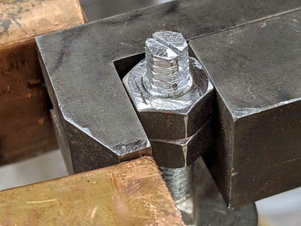
After the epoxy stiffened enough to hold its position, remove the bolt, file a crude ¼ inch hex, and saw a screwdriver slot to make it match the other feet:
HON Lateral File – new foot hex head
Not the fanciest job I’ve ever done, but it now behaves just like the other ones and it’s all good. The HON Storage Files FAQ points to a Troubleshooting Guide showing how to level the thing with a hex socket from inside the bottom drawer.
The flat heads on those bolts are basically 25 mm OD steel plates calling for fuzzy felt bumpers on the Sewing Room’s wood floors. When properly leveled, the front will be ⅛ inch higher than the rear. Although they suggest a pencil should roll toward the back, the top sheet metal on this one may be sufficiently warped to confuse the issue; I have a long level well suited to the task.
The original dimension doodle includes metric offsets for cutting with a ¼ inch end mill:
HON Foot nut – dimension doodles
All in all, a satisfying day in the Basement Shop …