Ed Nisley's Blog: Shop notes, electronics, firmware, machinery, 3D printing, laser cuttery, and curiosities. Contents: 100% human thinking, 0% AI slop.
We didn’t have any fires in the neighborhood where it might have been a problem, but I’ll try the water department this year …
Oddly, the water department repainted most of the fire hydrants along most of the roads last year. This one apparently didn’t qualify, for whatever reason, despite being only slightly off Rt 376 on Sheldon:
Frozen hydrant – Sheldon at Rt 376 – Google Streetview
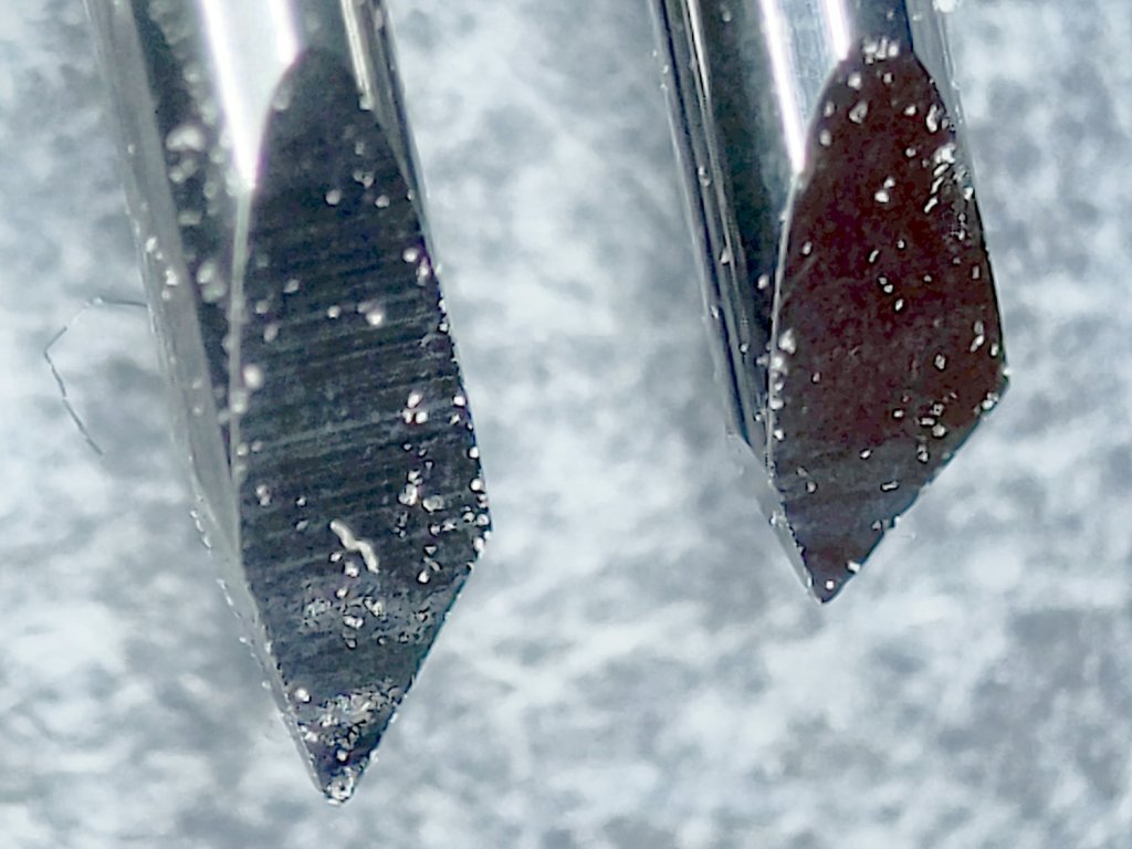
Having used the same two dragknifeblades intermittently over the last three-ish years, I wondered just how worn they’d gotten:
Drag Knife Blades – sides
For scale, the cylindrical part of the blade is 1.0 mm OD.
The blade with the longer face (left above and bottom below) has seen the most use and is definitely rounded at the tip:
Drag Knife Blades – tips
Three unused blades have sharp tips:
Drag Knife Blades – unused 60 45 30 degree
From the top, the (nominal) blade angles are 60°, 45°, and 30°, generally indicated by yellow, red, and blue plastic caps. However, various eBay sellers disagree on how to measure the angle (up from surface / outward from axis) and which cap colors correspond to which angles.
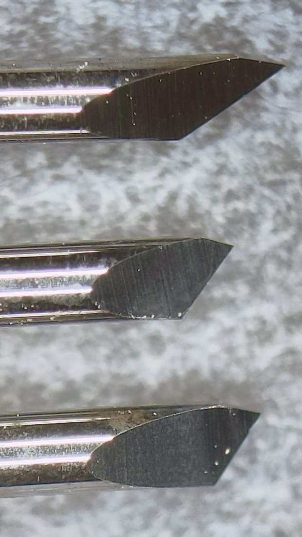
The unused 45° blade bracketed by the two used blades:
Drag Knife Blades – unused in center
The two lower blades have angles somewhere between 30° and 45°, suggesting slack grinder and QC tolerances. If the actual angle matters to you, buy an assortment (from one seller!), measure what you get, and don’t be surprised when the results aren’t anything in particular.
Perhaps, with careful attention to alignment in a non-pivoting / collet holder, one might scribe exceedingly narrow lines.
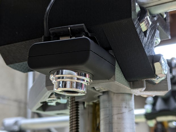
For the usual inscrutable reasons, updating bCNC killed the USB camera on the MPCNC, although it still worked fine with VLC. Rather than argue with it, I popped a more recent camera from the heap and stuck it onto the MPCNC central assembly:
bCNC – USB probe camera – attachment
This one has a nice rectangular case, although the surface might be horrible silicone that turns to snot after a few years. The fancy silver snout rotates to focus the lens from a few millimeters to infinity … and beyond!
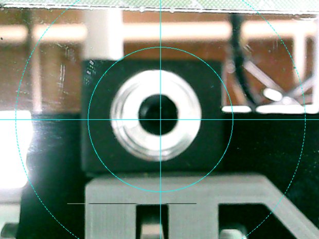
If you think it looks a bit off-kilter, you’re absolutely right:
bCNC – USB probe camera – off-axis alignment
The lens image reflected in a mirror on the platform shows the optical axis has nothing whatsoever to do with the camera case or lens snout:
bCNC – USB probe camera – off-axis reflection
Remember, the mirror reflects the lens image back to itself only when the optical axis is perpendicular to the mirror. With the mirror flat on the platform, the lens must be directly above it.
Because the MPCNC camera rides at a constant height over the platform, the actual focus & scale depends on the material thickness, but this should be typical:
bCNC – USB Probe Camera – scale – screenshot
It set up a Tek Circuit Computer test deck within 0.2 mm and the other two within 0.1 mm, so it’s close enough.
The image looks a whole lot better: cheap USB cameras just keep improving …
Another reducer had gone missing over the years, so I made one from a length of PVC pipe:
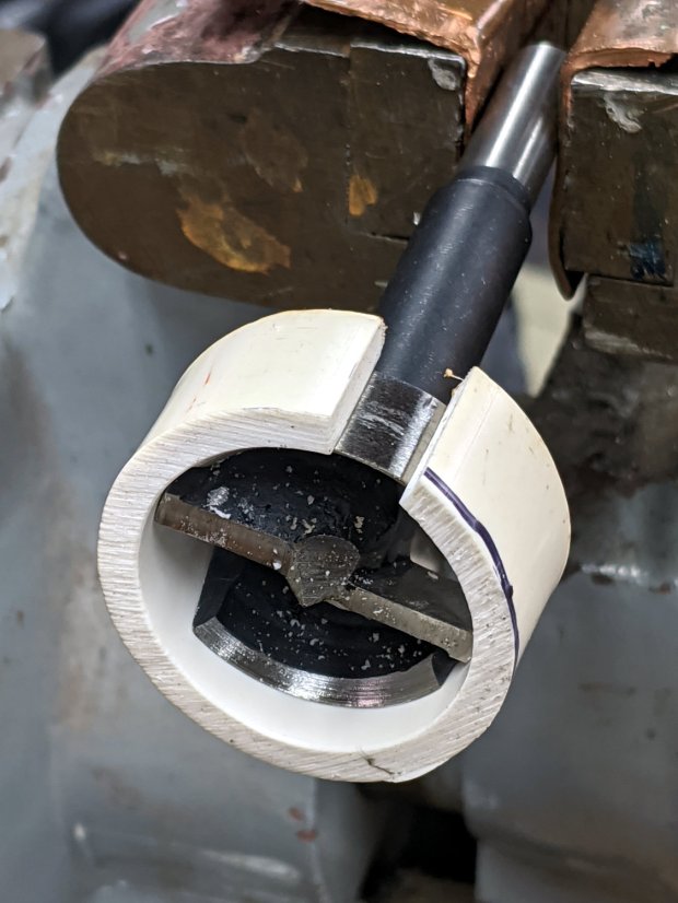
Bird Box – PVC pipe reducer – shaping
It started as 1-½ PVC pipe, 1-⅞ inch actual OD and should fit into a 1-½ hole, so I measured 1.5 × 3.15 around the circumference, bandsawed out the excess, draped it over a 1-½ Forstner bit, toasted it with a heat gun, and squashed it so it’s just a little bit bigger than the (enlarged!) hole in the box.
Now the entrance is 1-¼ (-ish), just like it should be:
Bird Box – PVC pipe reducer – installed
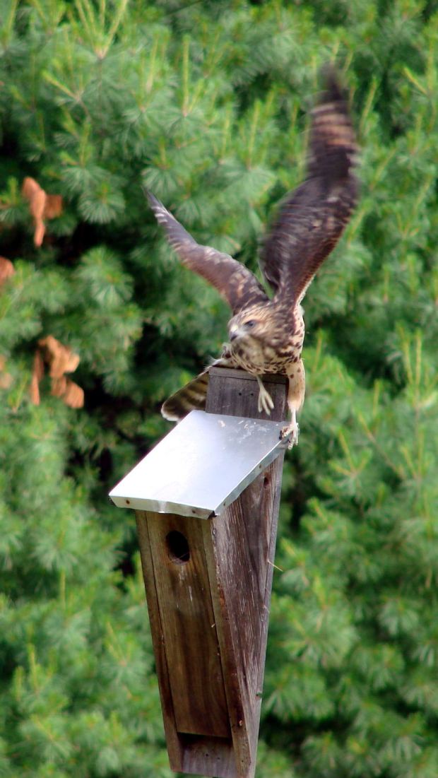
The bird box in the front yard has been attracting starlings, in addition to serving as a hawkperch:
New Coopers Hawks – bird box takeoff whoops
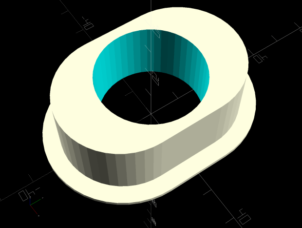
The oblong hole required advanced manufacturing techniques:
Oval Entrance Reducer
The front face should be too slick for larger birds and the little ones will zip right into the hole:
Bird Box – 3D printed entrance reducer
The two starlings who’d been evaluating the box seem to have moved on; we doubt they’re now homeless.
This file contains hidden or bidirectional Unicode text that may be interpreted or compiled differently than what appears below. To review, open the file in an editor that reveals hidden Unicode characters.
Learn more about bidirectional Unicode characters
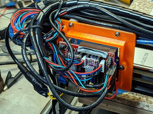
I’ll probably regret not adding pins along the entire row, but, unlike the MPCNC, the CNC 3018XL won’t ever have hard limit switches. I plugged the Run-Hold switch LEDs into an unused +5 V pin and moved on.
As is my custom, the day before showtime I talked my way through a final full-up dress rehearsal, with the HP 7475A plotter and the CNC 3018XL running their demo plots. As if to justify my attention to detail, the 3018 refused to home, with its X axis motor grinding in a manner suggesting something had gone terribly wrong with its driver.
OK, I can fix that™.
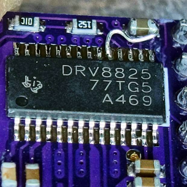
Turn off the power, verify the leadscrew turns smoothly by hand, check all the connections & connectors, then pull the DRV8825 PCB to see if anything looks obviously wrong. It didn’t, so I carefully re-plugged the driver and moved the whole affair to the Electronics Workbench for further study.
I turned on the scope and Tek current probes, then turned on the 3018 power supplies, whereupon a great cloud of Magic Smoke emerged from the CAMtool board and filled the Basement Laboratory with the acrid smell of Electrical Death.
It seems I carefully and meticulously re-plugged the DRV8825 PCB into its socket exactly one pin too high, which, among other Bad Things, connects the +24 V motor power supply to the driver GND pin.
Obviously, this did not end well:
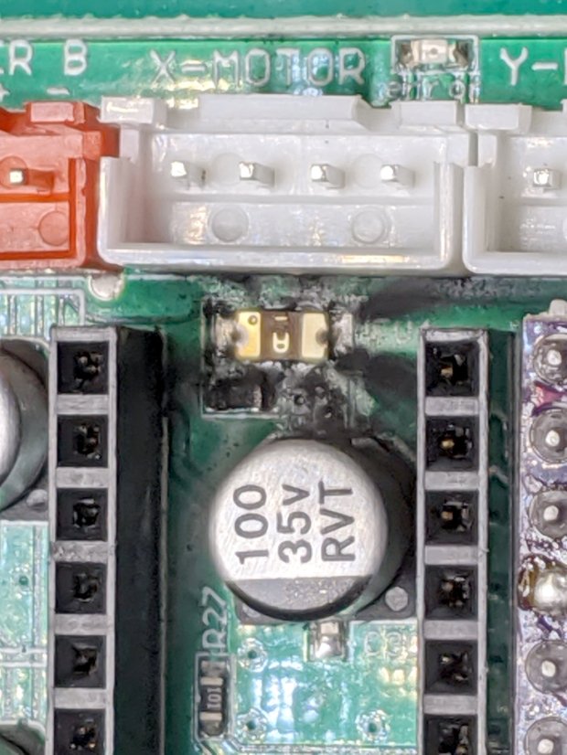
CAMtool V3.3 – blown stepper fuse
The fuse, put under considerable stress, vented smoke & debris in all directions across the board; note the jets above the white motor connector. Surprisingly, the 1 kΩ resistor just below it is in fine shape, as is the rather blackened electrolytic cap.
The fuse measures the same 150-ish mΩ as the fuses in the other two axes, but I doubt it’s actually a fuse any more.
Astonishingly, the Arduino clone on the board worked fine, so I could extract the GRBL configuration.
Memo to Self: Never plug things in with your head upside down!
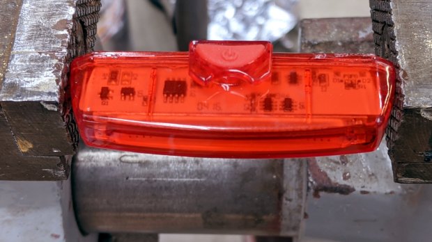
Along with the (defunct) Blackburn Flea, the bike pack also disgorged an anonymous taillight with a battery resistant to recharging through the USB port. Gentle suasion cracked the solvent-glued joint around the case:
Bike taillight – cracking case
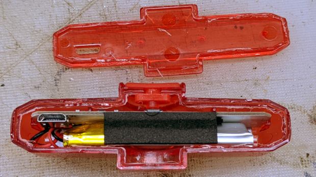
As with most modern electronics, a battery occupies most of the interior volume:
Bike taillight – opening case
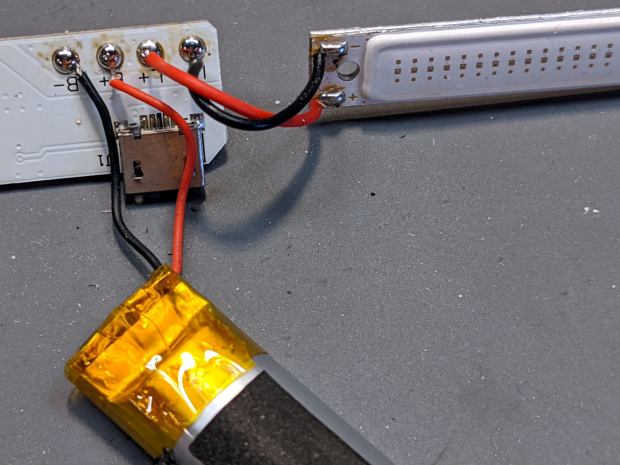
For posterity, the connections:
Bike taillight – connections
I unsoldered the cell and charged it from a bench supply:
Bike taillight – external recharge
The voltage started out low with the current held to about 100 mA, eventually rose to 4.1 V, and stayed there while the current dropped to zero. Unlike the Blackburn cell, it appears not too much worse for the experience, although I haven’t measured the actual capacity.
Clipping the Tek current probe around the LED supply wire produced this waveform for the “dim” setting:
Anonymous Taillight – Low – 200 mA-div
Adding a voltage probe across the LEDs and clicking to the “high” setting:
Anonymous Taillight – High – 200 mA-div
The intense ringing at the start of the pulse seems an artifact of the measurement setup, but ya never know; these days, RFI can come from anywhere.
In any event, the COB LED strip draws 800 mA from a fully charged battery, about 26 mA for each of the 30 LEDs. The 5% duty cycle in the “dim” setting is decently bright and 18% in “high” is entire adequate.
A trio of blinks works for daytime rides, although the fastest one seems seizure-inducing.
I’ve strapped it around a rack strut and run it at the slowest blink, on the principle you can never have too many blinky lights …