Ed Nisley's Blog: Shop notes, electronics, firmware, machinery, 3D printing, laser cuttery, and curiosities. Contents: 100% human thinking, 0% AI slop.
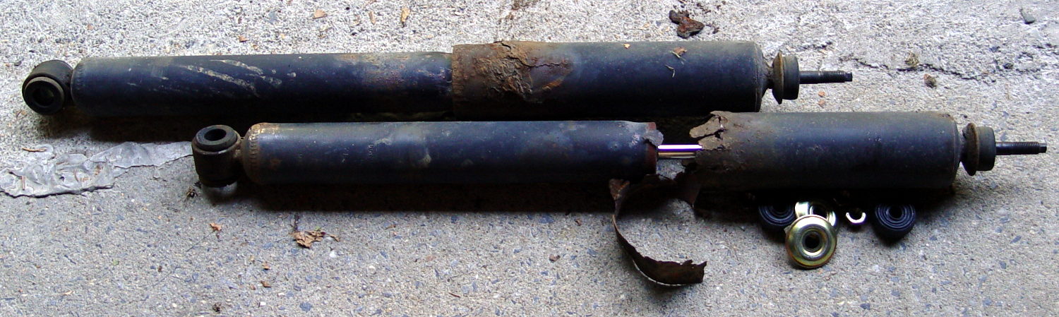
After the last annual inspection, the Nice Man told me that the rear shocks were rusted out and, although they still worked and he couldn’t fail the van, he wished he could. After 13 years and 88 k miles, yeah, they looked pretty grim:
Sienna OEM rear shocks – removed
The loose steel snippet came from the bottom of the outer shield; it had completely rusted off and dropped free around the lower mount. I suppose that was what got his attention.
Anyhow, the removal went astonishingly well:
Back the van out of the garage until the wheels line up with drop to the driveway apron
Pop inside dress covers over the struts
Remove top jam nuts, cushion, cups
Remove bottom bolt from wheel carrier (easily!)
Spritz penetrating on rubber bushing
Compress shock, twist until bushing slides free
And the installation was equally smooth:
Install shock on wheel carrier
Torque bottom bolt (29 ft·lb)
Aim strut at hole in body
Cut restraining wire, guide strut through hole
Install OEM bottom cup, new cushion & cup, new nylock nut
Tighten to same length as OEM nut
Install dress covers
The OEM cup fits snugly into the body hole to center the strut, so it seemed like a Good Idea to reuse it. Despite the rust stain inside the body, it was in reasonable condition.
You’re supposed to jack the van up while fiddling around underneath, but the driveway slopes down from the garage enough to provide access. I did chock the wheels, of course, but not jacking the van and putting it on stands looked like a major safety win right there.
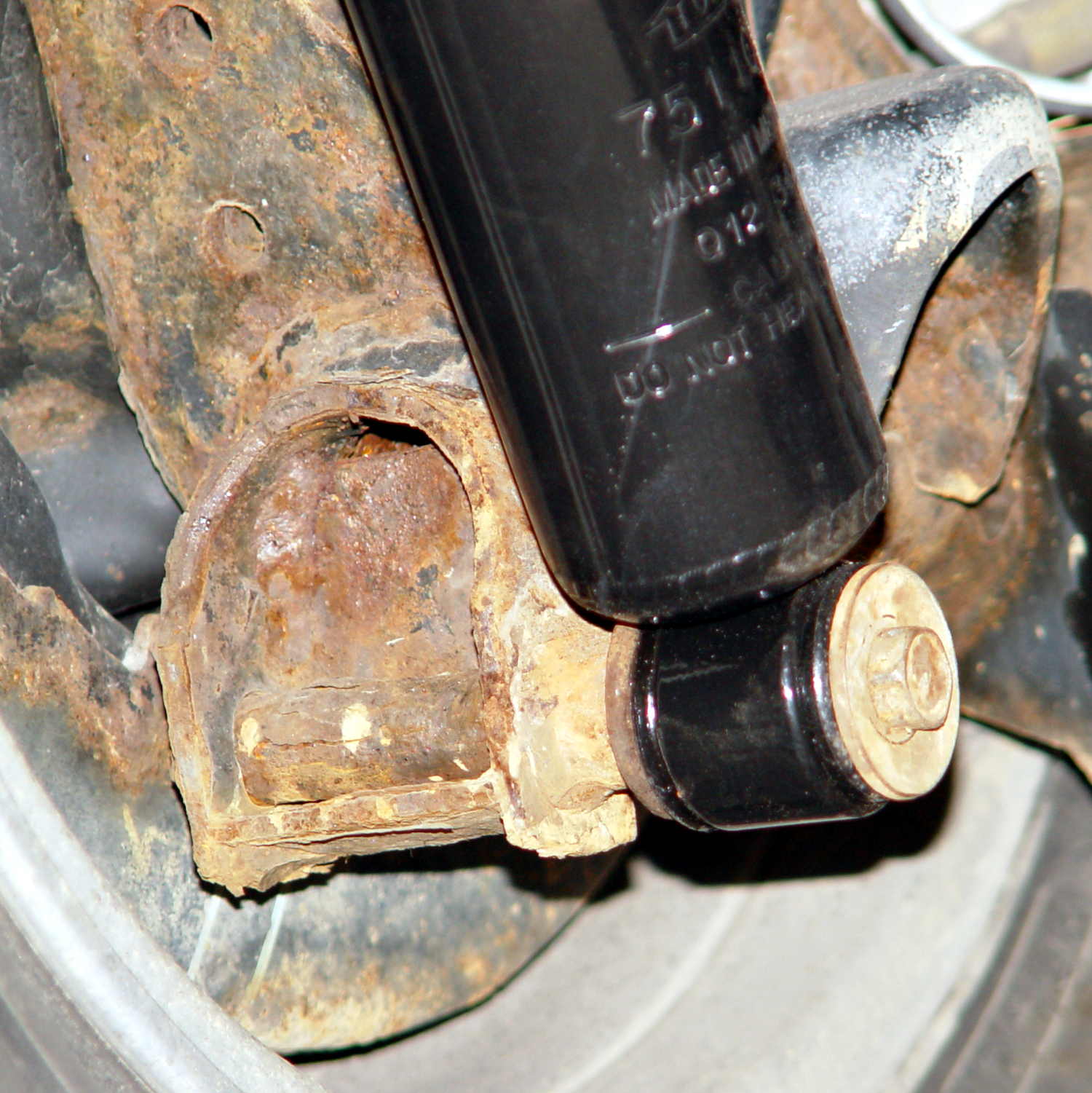
The bottom view, which shows the effect of a dozen New York State winters on ordinary steel:
Sienna replacement rear shocks – bottom
The top view, which shows that the bushings did leak a bit of water over the last decade:
Sienna replacement rear shocks – top
Done!
I suppose, just for completeness, I should do the front shocks, but those aren’t nearly as easy and I’d have to start by buying a spring compressor.
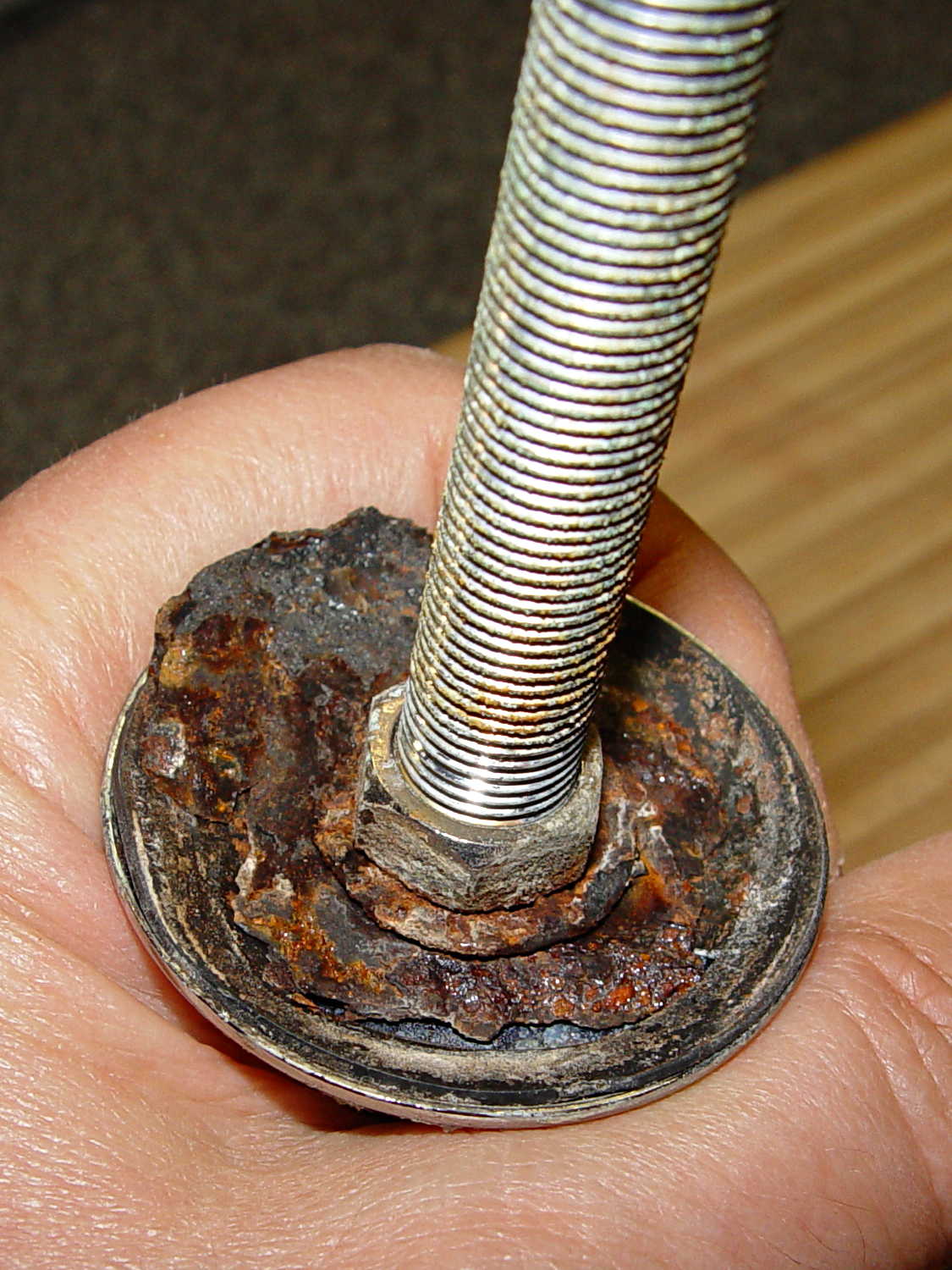
The kitchen sink has a small faucet that used to connect directly to the well out back, but now delivers town water from a line bypassing the water softener. The large steel washer below the sink deck has been shedding rust for a while and finally disintegrated:
Kitchen faucet – rusted washer assembly
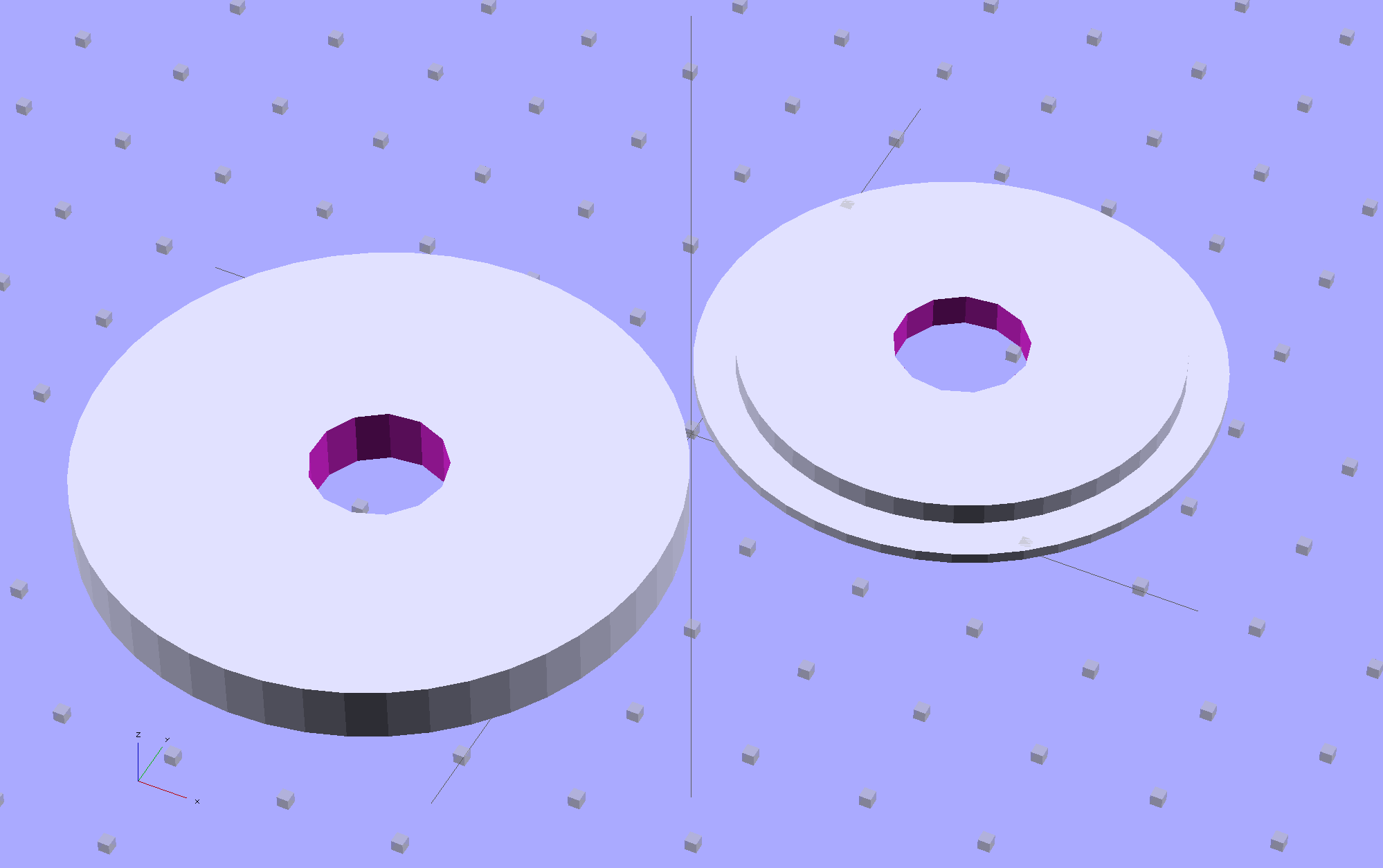
Well, this is a perfect application for plastic, not steel, so I conjured up a pair of disks:
Sink Base – Build
The large flat one goes below the sink deck in place of the steel washer and the smaller part of the stepped disk fits inside the deck opening to stabilize the faucet:
Sink Base – Show
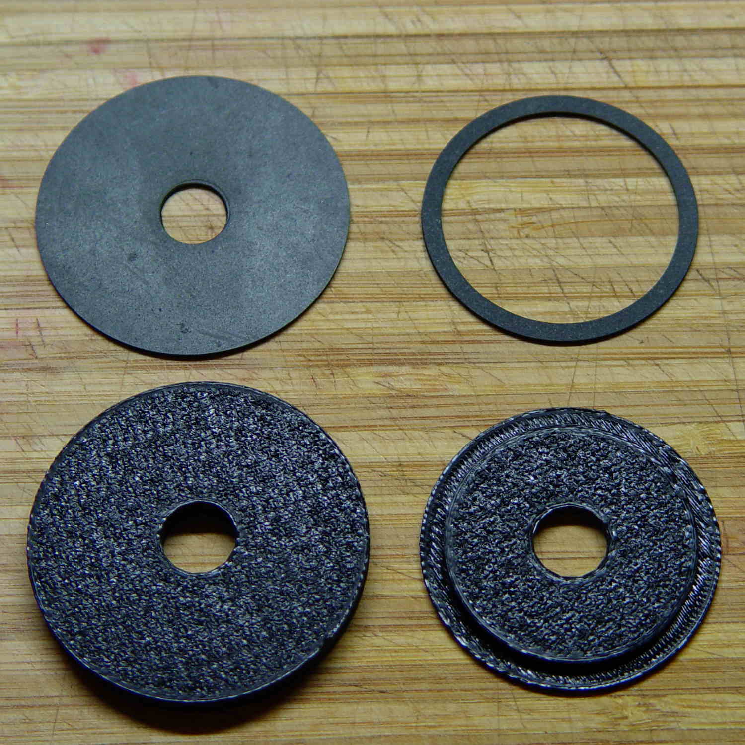
The two dark rings bracketing the deck between the orange plastic disks represent a pair of gaskets / washers / seals cut from 1 mm rubber sheet with a straight razor toting compass:
Kitchen faucet – plastic disks and rubber deck washers
Just for fun, I used Slic3r’s Hilbert Curve top and bottom fill pattern. It produces a nice, grainy texture that feels appropriate for anything needing a non-slip grip (at least on the top, as the bottom surface is glass-smooth).
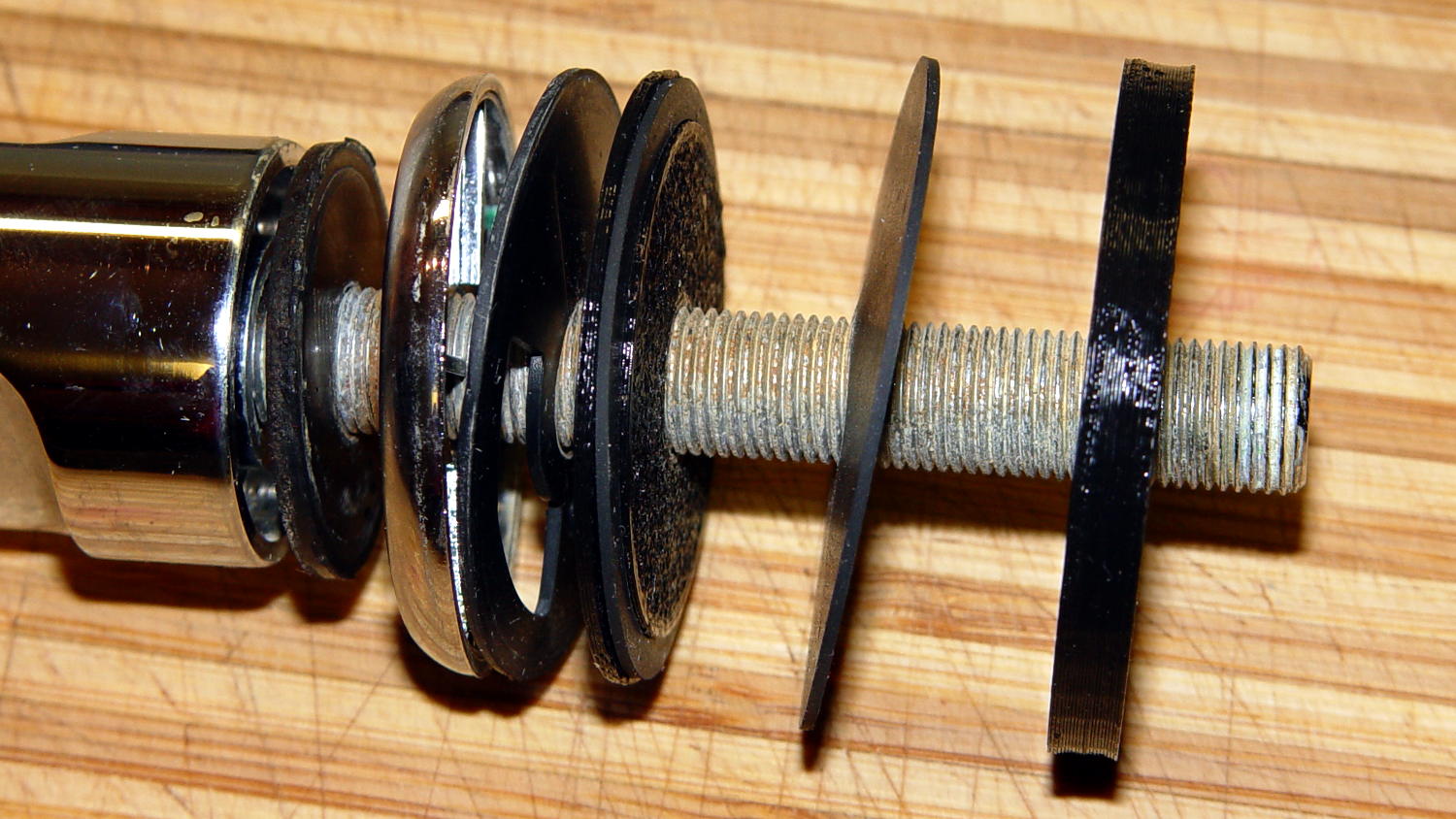
Everything stacks up thusly, with the top dark ring representing a rubber seal that came with the faucet:
Sink Base – Assemble
It looks about the same in real life, albeit minus all the colors:
Kitchen faucet – fitting stack
The black plastic and black rubber blend together and vanish amid all the chrome:
Kitchen faucet – assembled
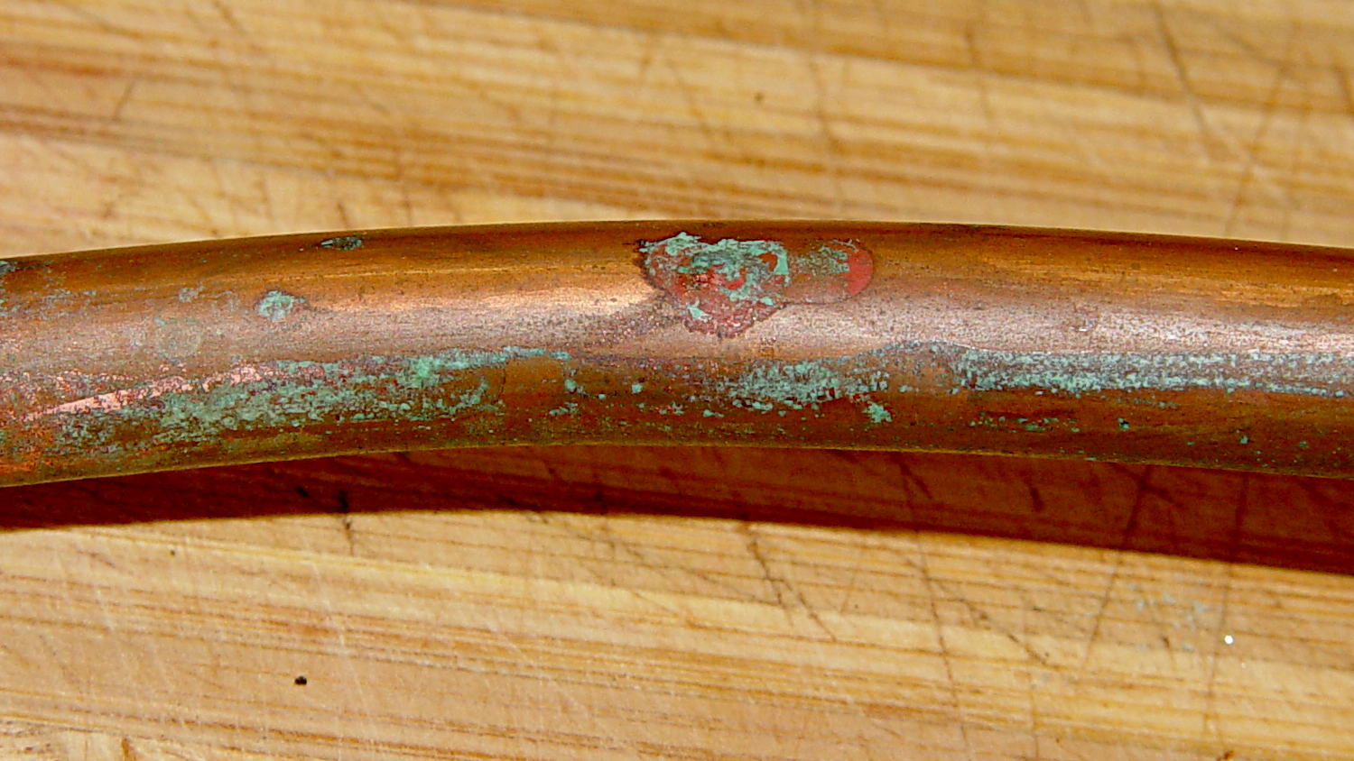
Alas, when I turned the water on, Mary said “That doesn’t sound right…” at about the same time I discovered a fine mist under the sink. See if you can spot the problem:
Kitchen faucet – corroded copper tube
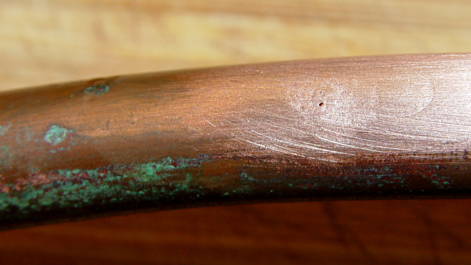
A shined-up view should make it obvious:
Kitchen faucet – corroded copper tube – pinhole
A trip to the precious metals aisle of the Big Box Home Repair Store produced a roll of 3/8 inch copper tubing, although I should have the stub end of that original roll somewhere in the heap. The fitting at the bottom of the faucet turned out to be completely non-standard and I had to re-use it with the new tubing, but it still sealed perfectly.
I hate plumbing jobs. That fix better last for another decade…
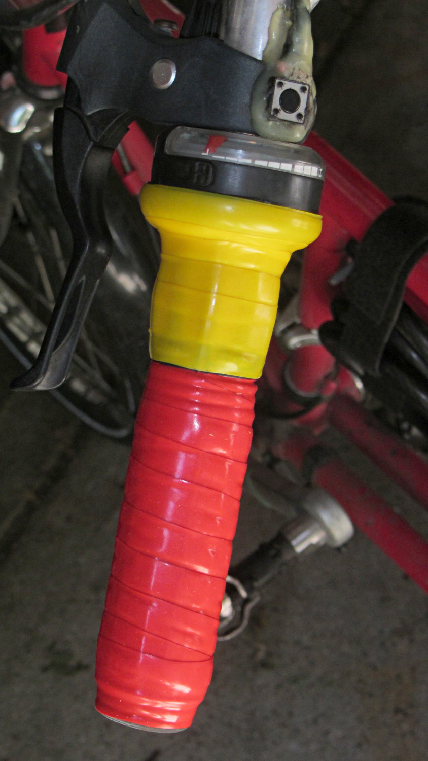
After more than a few years, the handlebar grips on my Tour Easy are rather worn, so I recently wrapped them with cheerful red and yellow silicone tape.
Back in the day, you wrapped with cork tape and had to worry about the direction on each side. Silicone tape fuses into a solid mass and the orientation shouldn’t matter; that’s a Good Thing, because I’m not sure what direction would be correct in this situation.
The yellow section covers the SRAM twist grip, which means it has a moving joint at each end. I suspect the tape will pull back from the larger part of the grip and form an unsightly lump just behind it.
It’s certainly much grippier than I expected…
(The small pushbutton switch is the PTT for the amateur radio HT that does voice and APRS/GPS.)
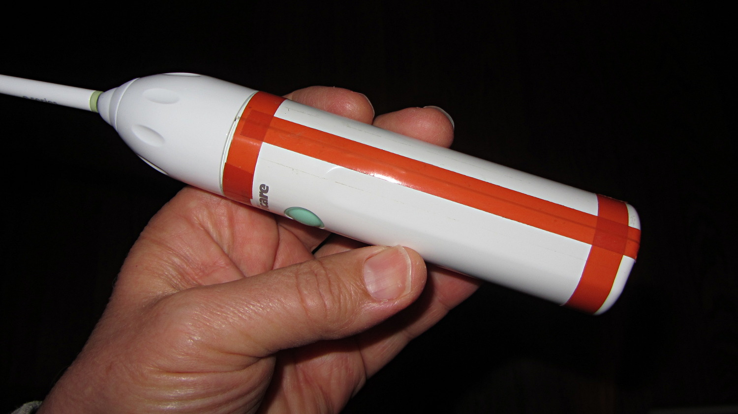
Much to my astonishment, the ordinary adhesive tape holding the Sonicare Essence power toothbrush together lasted for a bit over a year. As the tape splits along the gap in the case, the coil driving the brush head begins vibrating inside its nest, making a truly horrendous racket.
The new fix looks a bit odd, but works fine:
Sonicare Essence – red tape
The tape comes from Mad Phil’s stash and is, I think, splicing tape for reel-to-reel 1/4 inch recording tape: it has zero stretch, infinite strength, and adhesive that’s obviously lasted forever. The inside of the spool says “NOPI Made in Germany”, which doesn’t lead anywhere useful, although the NOPI name does seem to appear in a tape context.
After a year, the replacement NiMH cells are doing fine, still operating about once a day for three weeks from a 24 hour charge.
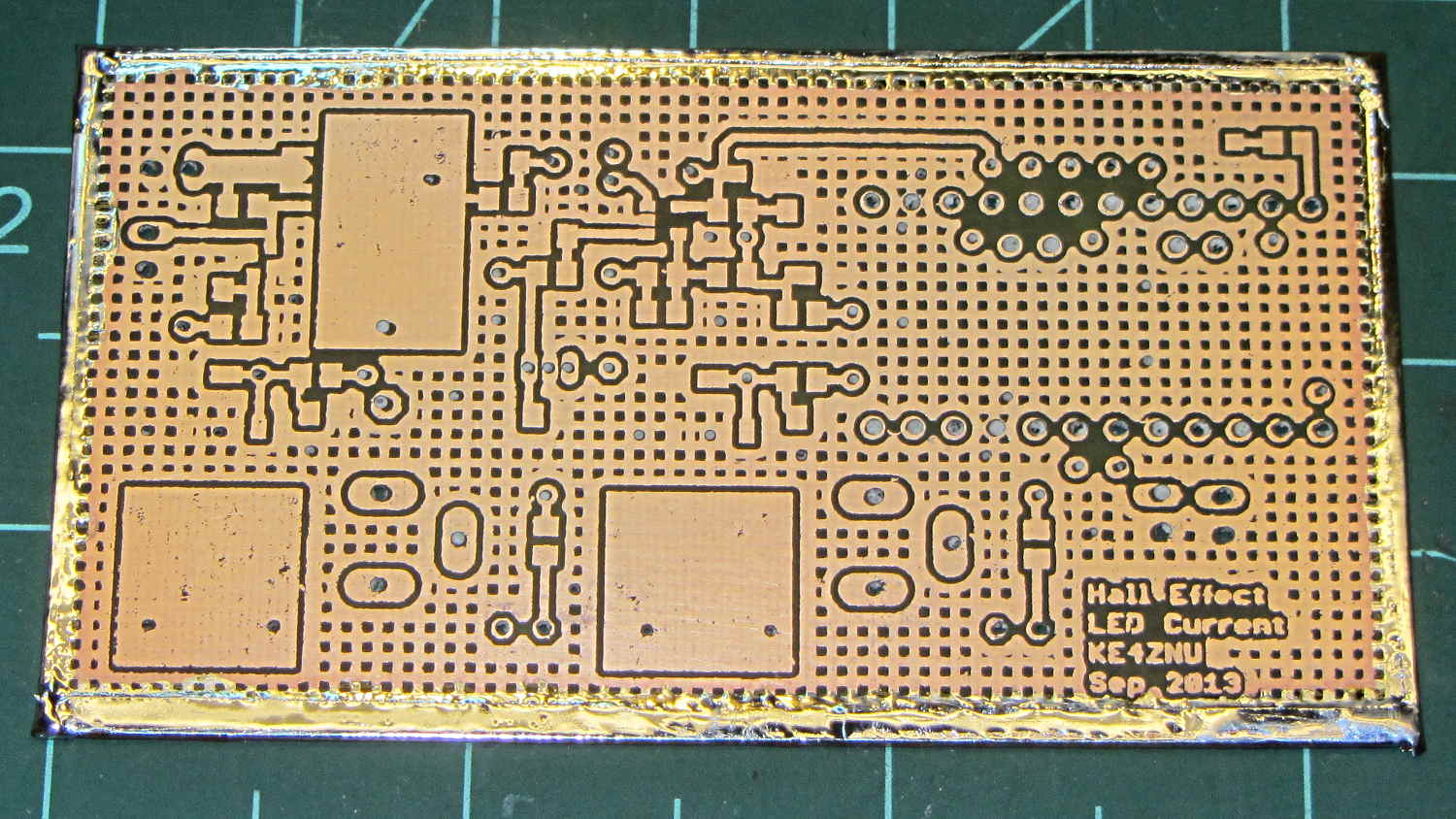
The big rectangle at the top will heatsink the main p-MOSFET power switch, which shouldn’t dissipate much power at all. The two lower rectangles heatsink the n-MOSFETs, although I think they may each require a stand-up metal tab to handle the dissipation during high-duty-cycle blinkiness.
The silver line around the edge is soldered copper foil tape connecting the top and bottom ground planes; a dozen or so additional Z wires will connect the planes at high current nodes. It’ll get a bunch of flying signal wires, too, because I’m not a fanatic gotta-embed-all-the-wires kind of guy on stuff like this.
The PCB is 30 mil FR4, which (once again, I make this mistake over and over again) seems a bit bendy for surface-mount parts; I must print a simple nest to stabilize the poor thing. Some of the drilled holes look white, because I hadn’t rinsed out the remains of the silver plating powder; the surfaces are a lot more silvery in person.
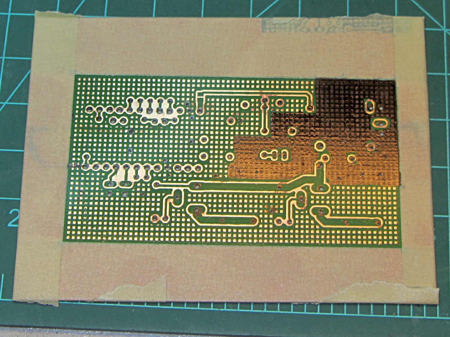
Before I etched the back side, I realized I’d made a classic layout blunder: the high-current return path from the center MOSFET flows around the Hall effect sensor near the center of the board. So I filled in the grid pour with a fat point black Sharpie to get more copper in that area:
Hall Effect Brassboard – added etch masking
I think it probably wouldn’t matter either way, but nothing exceeds like excess. FWIW, I use the grid pattern as a way to verify the end of the board etching: when all the holes in the ground pour come clear, all the traces are done, too.
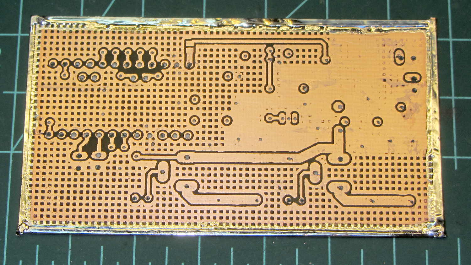
The etched backside came out OK, although with a few etched squares sprinkled in the Sharpie masking:
Hall Effect Brassboard – bare back
The three leads for the Hall effect sensor are just to the right of the center, with the middle lead connected to the ground pour. Given the millivolt-level signals, this isn’t a good place for ground bounce…
It’s etched with ferric chloride, rubbed with a sponge, and took under ten minutes on each side. That’s less than the usual time, which suggests the PCB is plated with half-ounce copper (that’s 0.5 ounce / ft2), rather than the one-ounce copper on the other boards I’ve done recently; just one of the hazards of buying surplus PCB stock. Doesn’t really matter, as the peak currents will be under half an amp and now I know not to use this batch of raw board stock for high current circuits.
All in all, it looks good enough. Now, for some component soldering.
The BOB Yak trailer I tote behind the ‘bent has a flag with a two-part pole which generally stays together; I pull the entire affair out of the frame socket when I hang the trailer up after a trip. The ferrule between the two pole sections recently worked loose and I took it to the Basement Workshop for repair.
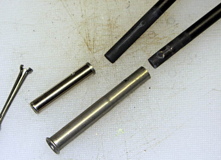
The assembled nickel-plated brass (?) ferrule came off both pole sections all too easily, which was a Bad Sign: those little punch marks originally clamped the tubes to the pole. You can’t overestimate the Bad Effects of prolonged vibration on bike parts.
Separating the two ferrule sections required running several pin punches down the bore and tapping gently, all accompanied by considerable muttering; the joint was no longer a slip fit. Eventually I produced this tableau:
BOB Yak trailer flag ferrule
The small hole gauge to the far left showed that the inside of the larger section (on the bottom) had entirely enough clearance for the smaller section, but the rolled ring at its end had somehow shrunk to a tight interference fit.
I’d actually chucked up a piece of rod in the lathe, with the intent of making a mandrel to expand the ring, when I came to my senses. The smaller part was 0.253 inch diameter, so I deployed the letter drills:
an E drill (0.250 inch) just kissed the inside of the ring
an F drill (0.257 inch) opened the ring to a nice sliding fit and still fit easily inside the tube
A few whacks with a center punch reclamped the dimples firmly in place on the dents in the poles.
I carry the Canon SX230HS in my pocket, so as to have a decent camera ready when it’s needed; yes, it’s in a cloth case. Unfortunately, in recent weeks a tiny hair made its way into the lens stack, where it shows up as a slight blurring just left of center in high f/stop images:
Cheap cartridge heater insulation
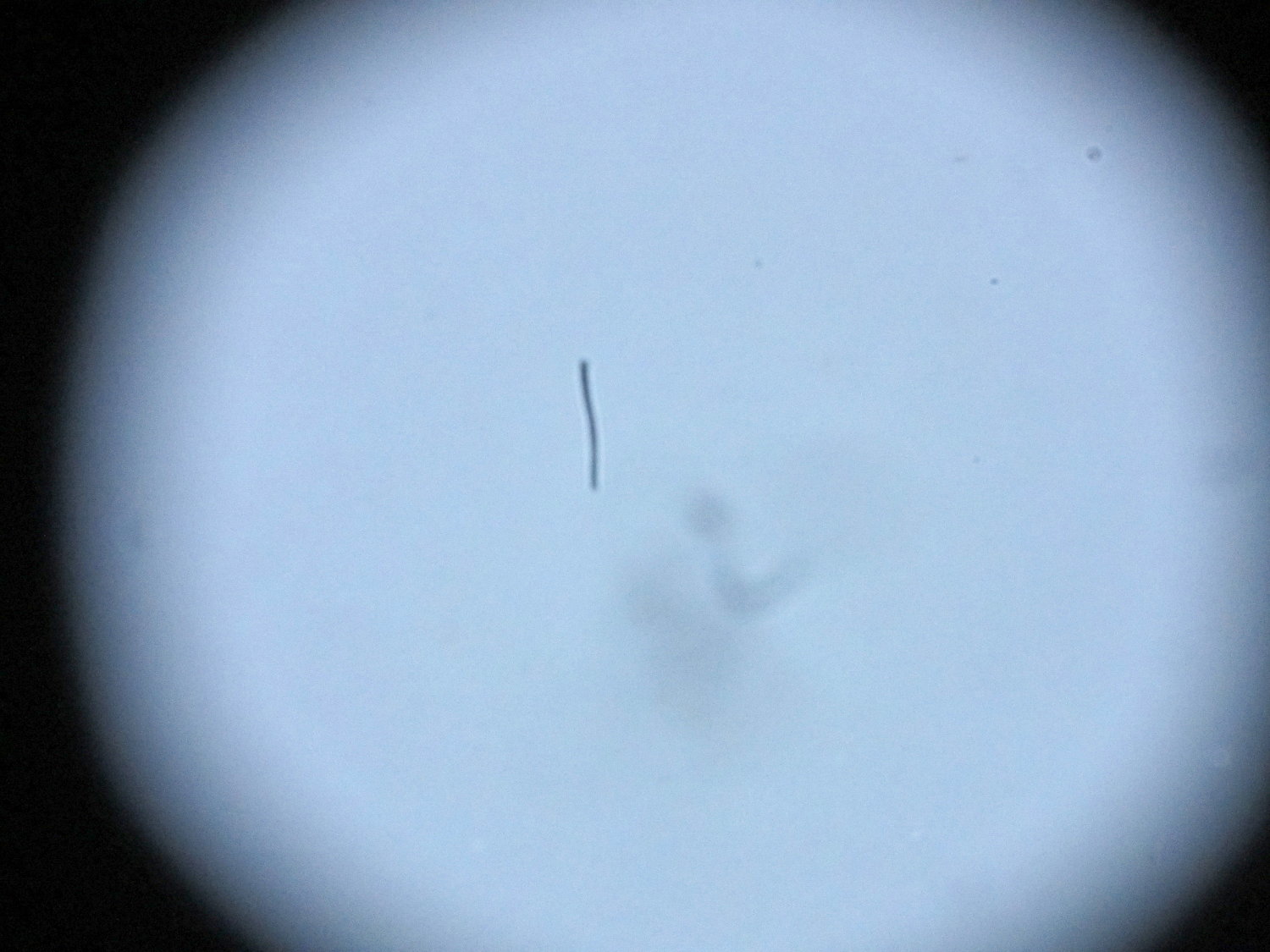
With the camera attached to the stereo zoom microscope, the hair becomes painfully obvious:
Hair on SX230HX Sensor
Of course it’s in the middle of the image. [sigh]
A bit of searching turns up a bootleg technique to remove the front lens from the turret (basically, just twist and pull), but neither of the internal lens surfaces thus revealed lie near a focal plane and, in any event, were surprisingly clean. The hair is probably lodged just in front of the image sensor, most likely stuck to the back of the final lens where it casts a shadow on the sensor. If it wandered around you’d call it a floater.
Dismantling the entire camera and opening the lens stack seems fraught with peril, particularly as the camera pretty much still works fine for normal picture-taking. More pondering is in order…