The Smell of Molten Projects in the Morning

Ed Nisley's Blog: Shop notes, electronics, firmware, machinery, 3D printing, laser cuttery, and curiosities. Contents: 100% human thinking, 0% AI slop.

Tag: Repairs

If it used to work, it can work again

  • Tour Easy: Yet Another Shifter Pulley

    Somehow, I think I’m never going to get around to doing a CNC version of this thing, but at least now I have more pictures…

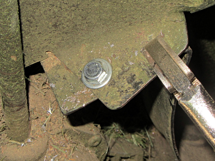
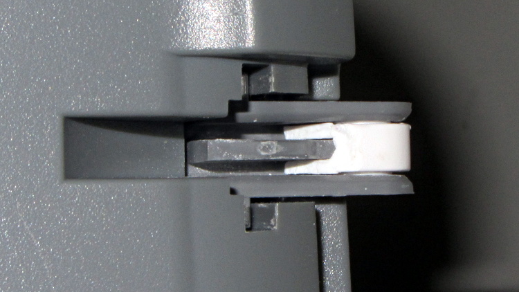
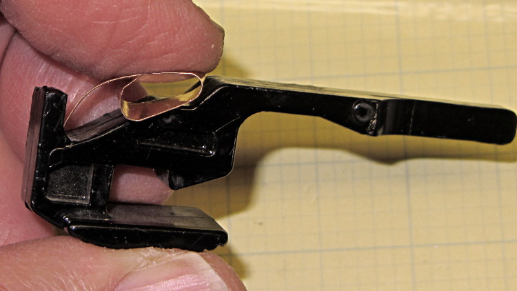
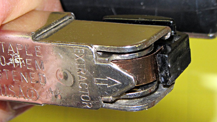
    The overall problem comes from the fact that the Tour Easy frame geometry doesn’t match the expectations of the front shifter: the cable bends over a small finger that, on a diamond frame bike, should simply hold it in position. Here’s the finger, with a very early version of the pulley that just holds the cable slightly higher than the normal position, complete with one snapped wire showing that the pulley wasn’t getting the job done:

    Front derailleur cable - broken strand
    Front derailleur cable with broken strand

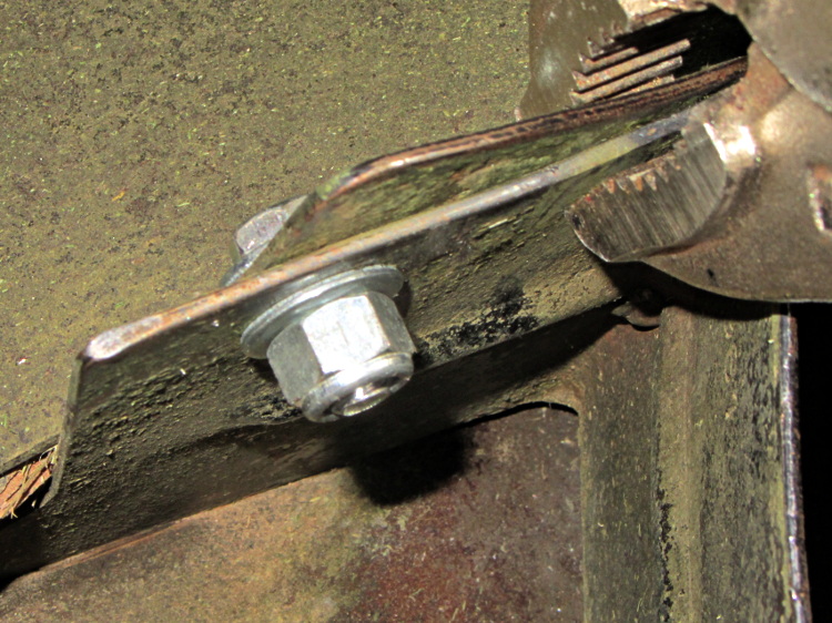
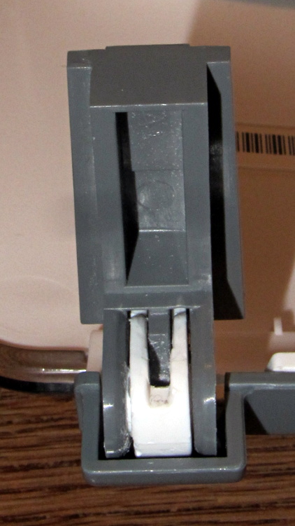
    The obvious solution involves running the cable over a nice, rounded surface that prevents abrupt bending. The most recent version looks like this:

    Shifter pulley installed - left view
    Shifter pulley installed – left view

    Yes, the end of the cable sticks out over the chain; I haven’t tucked it in yet.

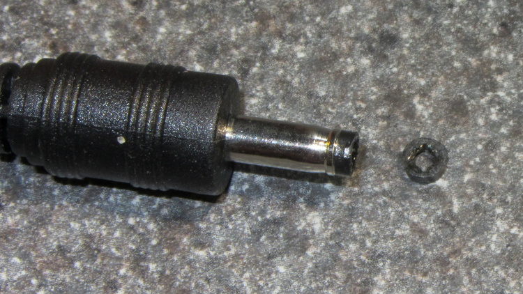
    A bit of lathe work produces a 0.42 inch diameter thin brass disk with a 50 mil half-circle trench around it; in retrospect, the diameter of the trench bottom should be 0.42 inch and the OD should be about 0.45 inch. If you have really good parting-off-fu, you can produce a disk with a finished backside right on the lathe, but I had to drill an off-center hole anyway, so I thinned it on the Sherline:

    Shifter pulley - thinning
    Shifter pulley – thinning

    It looks like this after all the thinning:

    Shifter pulley - thinned
    Shifter pulley – thinned

    One flange is wider than the other: the thin flange faces front and gets a bunch of cutouts, the wide flange faces rearward and must support the bitter end of the cable.

    I lined it up in the shifter, filed a notch to fit around the shifter finger, scribed the hole location, clamped it down, and drilled the hole:

    Shifter pulley - center drilling
    Shifter pulley – center drilling

    I think the hole could be on-center with the larger disk; now that I’m keeping better notes, I’ll try that next time. If so, then I can drill it on the lathe, part it off to the correct width, and hand-file the backside flat. The general idea is to have the cable pass over the finger, which almost happens with the smaller diameter.

    Some tedious hand-filing produces notches that index over the finger and clear some protuberances on the shifter arm. This is the front face of the pulley that sits against the shifter arm, with a 5 mm socket head cap screw for scale:

    Shifter pulley with bolt - front face
    Shifter pulley with bolt – front face

    The rear face has one side of the trench filed away to get the cable out of the trench and around the bolt:

    Shifter pulley with bolt - rear face
    Shifter pulley with bolt – rear face

    Then it looks like this from the right side of the bike:

    Shifter pulley installed - right view
    Shifter pulley installed – right view

    A pleasant morning with some Quality Shop Time…

  • Sears Mower Housing Repair

    The lawn mower began emitting horrible crashes, which turned out to be coming from a flange at the rear of the mower housing that was formerly spot-welded to the main chassis. Those welds broke and the flange occasionally vibrated into contact with the blade, causing heartache and confusion for both parties.

    Re-spot-welding the flange wasn’t in the cards, but the elaborately formed piece of steel did have a flat section in contact with another part of the chassis with just enough meat for a bolt. I grabbed the two with a Vise-grip, whacked the flange until it was more-or-less lined up where it should be, drilled a hole, and popped in a 1/4-20 bolt:

    Mower flange - side view
    Mower flange – side view

    The curved section of the flange faces the blade, with the vertical end pointed anti-spinward: the blade nicks that edge.

    A dab of red Loctite and a nylock nut topped it off:

    Mower flange - bottom view
    Mower flange – bottom view

    Then I could complete the mission…

  • Roof De-Icing Cable Numbers

    Having recently kibitzed on a project using de-icing cables (with some success) to soften PVC pipe for bending, herewith the useful numbers.

    Data printed on the original cable:

    • 100 ft length
    • 120 VAC
    • 800 W

    Derived values:

    • 6.7 A = 800 W / 120 V
    • 8 W/ft = 800 W / 100 ft
    • 1.2 V/ft = 120 V / 100 ft
    • 18 Ω = (120 V)2 / 800 W
    • 180 mΩ/ft = 18 Ω / 100 ft

    The starting point was a 62 ft length of the cable, as I’d long ago converted the end into a heated bed for starting plants early in the spring. That presented a resistance of 11 Ω, drew a current of 11 A, and dissipated 1.3 kW at 21 W/ft. A kilowatt-class dimmer handled the load, but adjoining sections of the cable got hot enough to melt the insulation and terminate the experiment.

    A shorter length of cable might be suitable for a cheap laptop brick power supply. To keep the dissipation under, say, 10 W/ft, we have:

    • 7.5 A = sqrt( 10 W/ft / 180 mΩ/ft )
    • 1.3 V/ft = 7.5 A * 180 mΩ/ft

    The Dell D220P-01 brick on the M2 provides 12 V at 18 A (!) and costs under $20 on eBay:

    • 9 ft = 12 V / 1.3 V/ft
    • 90 W = 12 V * 7.5 A
    • 1.6 Ω = 9 ft * 180 mΩ/ft

    You could run two 9 ft lengths cables in parallel from the same hulking brick. Whether that’s enough to soften a length of PVC pipe from the inside, without having the insulation get all melty, that’s another question…

  • HP ScanJet 3970 Lid Hinge Re-Repair

    As expected, that repair didn’t last very long at all; one hinge fractured along the same line as before. This time, however, we had a visit already in-plan, so I brought along my solvents and clamps.

    Perhaps you wondered how I could have been so remiss as to not brace those thin white flanges. One picture of the unbroken hinge in the “lid down” position is worth a thousand words:

    HP 3970 Scanjet - intact hinge
    HP 3970 Scanjet – intact hinge

    Need more? Here’s another thousand words from the other side:

    HP 3970 Scanjet - intact hinge pivot
    HP 3970 Scanjet – intact hinge pivot

    As the lid opens, the gray tab pivots toward the edge of the lid until it’s nearly parallel, at which point all of the force tries to yank those two flanges apart and then crack the tiny solid part at the pivot pin.

    Eventually, it succeeds. This is a view of the scanner base with the gray tab inserted in its slot, with the broken hinge in the “lid up” position:

    HP 3970 Scanjet - broken hinge pivot
    HP 3970 Scanjet – broken hinge pivot

    Clever design, no?

    I was unable to extract the broken fragment from the gray tab (actually, unwilling to apply more force, as I cracked part of the gray ring around the hinge pin), so this became an in situ repair. Once again, I applied solvent glue and squished the pieces together:

    HP 3970 Scanjet - glued hinge
    HP 3970 Scanjet – glued hinge

    And clamped it while we ate lunch:

    HP 3970 Scanjet - hinge clamping
    HP 3970 Scanjet – hinge clamping

    The brass rod applies the clamping force to the fractured part of the hinge through the pivot point. This isn’t the most stable clamp arrangement you’ve ever seen, but it worked well enough.

    I pushed the scanner back half a foot, so the lid now clunks against the wall just before the hinges reach their limit. Maybe they’ll survive until the next visit…

  • Coaxial Power Plug Tip: Extraction Thereof

    Another coaxial power plug lost its tip inside a lithium ion battery pack used with the APRS + Voice circuitry on our bikes, as I could barely see at the bottom of the socket:

    LiIon Pack - output socket
    LiIon Pack – output socket

    Rather than cutting the pack apart, I buttered up the end of an intact plug with some ABS solvent glue (a hellish homebrew mixture of acetone and MEK), rammed it into the socket, and held it in place for a minute:

    LiIon Pack - undamaged plug insertion
    LiIon Pack – undamaged plug insertion

    The tip emerged on the first try:

    LiIon Pack - rescued plug tip joined
    LiIon Pack – rescued plug tip joined

    Even better, it cracked off the plug without too much effort:

    LiIon Pack - rescued plug tip separated
    LiIon Pack – rescued plug tip separated

    More solvent glue and a few hours of clamping worked fine:

    LiIon Pack - clamped plug tip
    LiIon Pack – clamped plug tip

    That cable is now back in service.

  • BOB Yak Trailer: New New Grenade Pin Straps

    Somehow, I thought those neoprene O-rings that replaced the grenade pin straps on my BOB Yak trailer would last more than one season, but they’ve already rotted out. A bit of rummaging produced a hank of rubber gasket intended to secure window screen in its aluminum frame, so it’s presumably better suited to an outdoor life than O-rings; it comes without provenance, so I have no idea what it’s made of.

    A few snips, a handful of cable ties, and it’s all good again:

    BOB Yak Grenade Pins - new strap
    BOB Yak Grenade Pins – new strap

    But I’m not expecting a decade out of these straps, that’s fer shure…

  • Stapler Latch Spring Replacement

    It’s garden fence stapling season, which means it’s time for the annual stapler annoyance. There’s supposed to be a plastic tab angling under the right side of the latch, pressing against the bottom of the staple channel and forcing the triangular tab on the top out through a small opening. All that’s left is the stub:

    Stapler latch - broken spring tab
    Stapler latch – broken spring tab

    It looks like it ought to be a great 3D printing project, but I came to my senses and snipped off a length of phosphor bronze spring stock, rolled it up, and positioned it inside the opening:

    Stapler latch - metal spring fitting
    Stapler latch – metal spring fitting

    The latch slides into the staple channel until the pin on the side you can see above engages a hole in the channel. The spring looked like this on the way in:

    Stapler latch - before closing
    Stapler latch – before closing

    And now it’s ready for action:

    Stapler latch - in place
    Stapler latch – in place

    Works like a champ and took maybe 15 minutes, tops, to accomplish. Shame it took me a few decades to get around to fixing it, but I finally dropped the clipped-and-filed nail I’d been jamming between the latch and the channel one too many times…