Ed Nisley's Blog: Shop notes, electronics, firmware, machinery, 3D printing, laser cuttery, and curiosities. Contents: 100% human thinking, 0% AI slop.
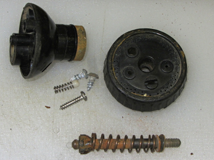
Evidently, it’s impossible to make a spring both good and noncorrosive:
Garden sprayer – corroded spring
I found a suitable (i.e., good, but rust-prone) spring in the Big Box o’ Medium Springs:
Garden sprayer – spring replaced
Unlike the repair for that sprayer, this spring turned out to be long enough to work perfectly. I have no idea how long I can keep this up, but … at least I’m now keeping pace with the failures.
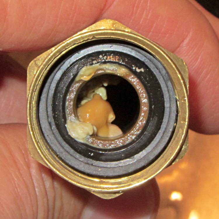
One of my fundamental rules is that you should never, ever look inside the water lines serving your faucets. Having recently replaced a water heater, I had to violate that rule and discovered this growth inside the flex tube at the hot water outlet:
Somehow, I think I’m never going to get around to doing a CNC version of this thing, but at least now I have more pictures…
The overall problem comes from the fact that the Tour Easy frame geometry doesn’t match the expectations of the front shifter: the cable bends over a small finger that, on a diamond frame bike, should simply hold it in position. Here’s the finger, with a very early version of the pulley that just holds the cable slightly higher than the normal position, complete with one snapped wire showing that the pulley wasn’t getting the job done:
Front derailleur cable with broken strand
The obvious solution involves running the cable over a nice, rounded surface that prevents abrupt bending. The most recent version looks like this:
Shifter pulley installed – left view
Yes, the end of the cable sticks out over the chain; I haven’t tucked it in yet.
A bit of lathe work produces a 0.42 inch diameter thin brass disk with a 50 mil half-circle trench around it; in retrospect, the diameter of the trench bottom should be 0.42 inch and the OD should be about 0.45 inch. If you have really good parting-off-fu, you can produce a disk with a finished backside right on the lathe, but I had to drill an off-center hole anyway, so I thinned it on the Sherline:
Shifter pulley – thinning
It looks like this after all the thinning:
Shifter pulley – thinned
One flange is wider than the other: the thin flange faces front and gets a bunch of cutouts, the wide flange faces rearward and must support the bitter end of the cable.
I lined it up in the shifter, filed a notch to fit around the shifter finger, scribed the hole location, clamped it down, and drilled the hole:
Shifter pulley – center drilling
I think the hole could be on-center with the larger disk; now that I’m keeping better notes, I’ll try that next time. If so, then I can drill it on the lathe, part it off to the correct width, and hand-file the backside flat. The general idea is to have the cable pass over the finger, which almost happens with the smaller diameter.
Some tedious hand-filing produces notches that index over the finger and clear some protuberances on the shifter arm. This is the front face of the pulley that sits against the shifter arm, with a 5 mm socket head cap screw for scale:
Shifter pulley with bolt – front face
The rear face has one side of the trench filed away to get the cable out of the trench and around the bolt:
Shifter pulley with bolt – rear face
Then it looks like this from the right side of the bike:
The lawn mower began emitting horrible crashes, which turned out to be coming from a flange at the rear of the mower housing that was formerly spot-welded to the main chassis. Those welds broke and the flange occasionally vibrated into contact with the blade, causing heartache and confusion for both parties.
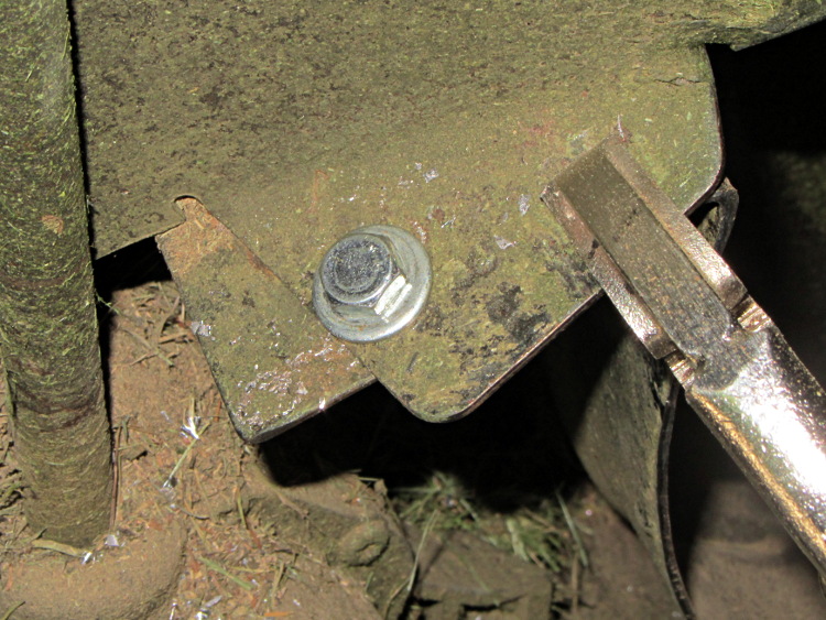
Re-spot-welding the flange wasn’t in the cards, but the elaborately formed piece of steel did have a flat section in contact with another part of the chassis with just enough meat for a bolt. I grabbed the two with a Vise-grip, whacked the flange until it was more-or-less lined up where it should be, drilled a hole, and popped in a 1/4-20 bolt:
Mower flange – side view
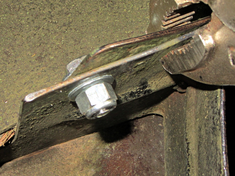
The curved section of the flange faces the blade, with the vertical end pointed anti-spinward: the blade nicks that edge.
A dab of red Loctite and a nylock nut topped it off:
Having recently kibitzed on a project using de-icing cables (with some success) to soften PVC pipe for bending, herewith the useful numbers.
Data printed on the original cable:
100 ft length
120 VAC
800 W
Derived values:
6.7 A = 800 W / 120 V
8 W/ft = 800 W / 100 ft
1.2 V/ft = 120 V / 100 ft
18 Ω = (120 V)2 / 800 W
180 mΩ/ft = 18 Ω / 100 ft
The starting point was a 62 ft length of the cable, as I’d long ago converted the end into a heated bed for starting plants early in the spring. That presented a resistance of 11 Ω, drew a current of 11 A, and dissipated 1.3 kW at 21 W/ft. A kilowatt-class dimmer handled the load, but adjoining sections of the cable got hot enough to melt the insulation and terminate the experiment.
A shorter length of cable might be suitable for a cheap laptop brick power supply. To keep the dissipation under, say, 10 W/ft, we have:
7.5 A = sqrt( 10 W/ft / 180 mΩ/ft )
1.3 V/ft = 7.5 A * 180 mΩ/ft
The Dell D220P-01 brick on the M2 provides 12 V at 18 A (!) and costs under $20 on eBay:
9 ft = 12 V / 1.3 V/ft
90 W = 12 V * 7.5 A
1.6 Ω = 9 ft * 180 mΩ/ft
You could run two 9 ft lengths cables in parallel from the same hulking brick. Whether that’s enough to soften a length of PVC pipe from the inside, without having the insulation get all melty, that’s another question…
As expected, that repair didn’t last very long at all; one hinge fractured along the same line as before. This time, however, we had a visit already in-plan, so I brought along my solvents and clamps.
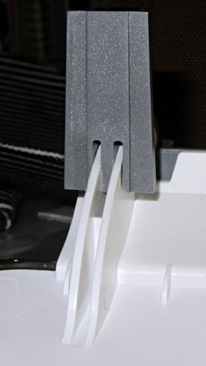
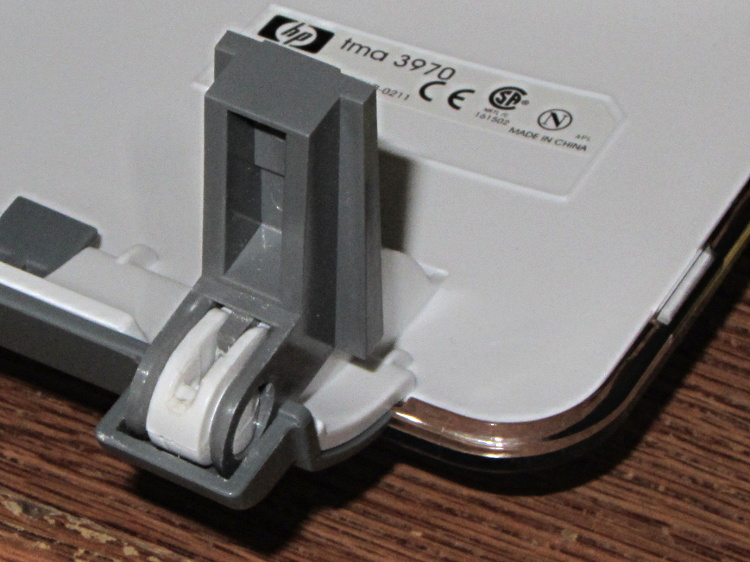
Perhaps you wondered how I could have been so remiss as to not brace those thin white flanges. One picture of the unbroken hinge in the “lid down” position is worth a thousand words:
HP 3970 Scanjet – intact hinge
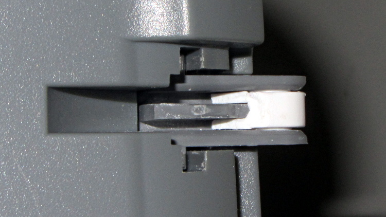
Need more? Here’s another thousand words from the other side:
HP 3970 Scanjet – intact hinge pivot
As the lid opens, the gray tab pivots toward the edge of the lid until it’s nearly parallel, at which point all of the force tries to yank those two flanges apart and then crack the tiny solid part at the pivot pin.
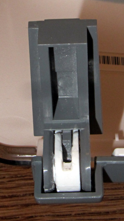
Eventually, it succeeds. This is a view of the scanner base with the gray tab inserted in its slot, with the broken hinge in the “lid up” position:
HP 3970 Scanjet – broken hinge pivot
Clever design, no?
I was unable to extract the broken fragment from the gray tab (actually, unwilling to apply more force, as I cracked part of the gray ring around the hinge pin), so this became an in situ repair. Once again, I applied solvent glue and squished the pieces together:
HP 3970 Scanjet – glued hinge
And clamped it while we ate lunch:
HP 3970 Scanjet – hinge clamping
The brass rod applies the clamping force to the fractured part of the hinge through the pivot point. This isn’t the most stable clamp arrangement you’ve ever seen, but it worked well enough.
I pushed the scanner back half a foot, so the lid now clunks against the wall just before the hinges reach their limit. Maybe they’ll survive until the next visit…
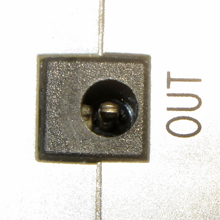
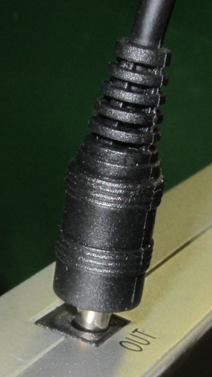
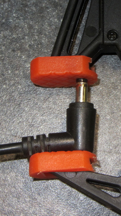
Rather than cutting the pack apart, I buttered up the end of an intact plug with some ABS solvent glue (a hellish homebrew mixture of acetone and MEK), rammed it into the socket, and held it in place for a minute:
LiIon Pack – undamaged plug insertion
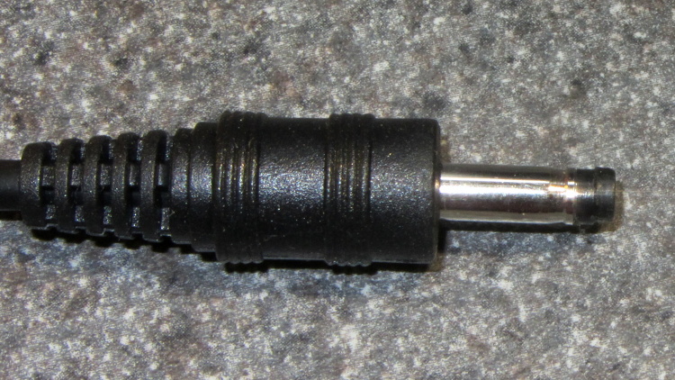
The tip emerged on the first try:
LiIon Pack – rescued plug tip joined
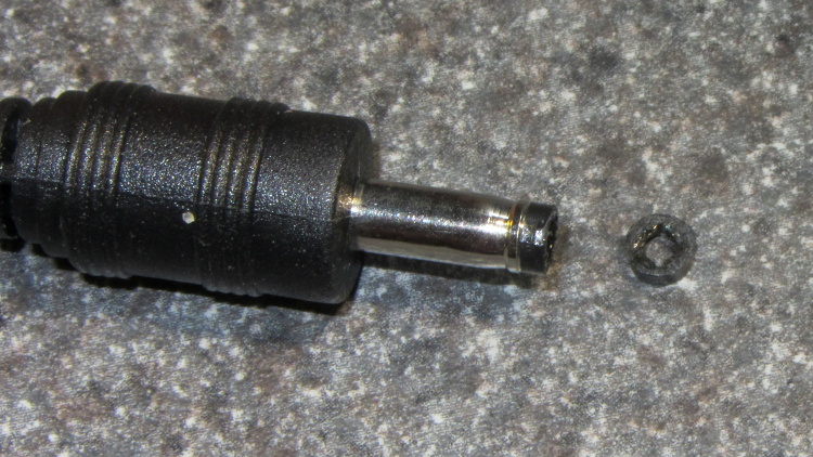
Even better, it cracked off the plug without too much effort:
LiIon Pack – rescued plug tip separated
More solvent glue and a few hours of clamping worked fine: