A one-year-old magnesium rod looks pretty good, all things considered:

The previous one was still working after seven years, although I had to wreck it to get it out…
The Smell of Molten Projects in the Morning
Ed Nisley's Blog: Shop notes, electronics, firmware, machinery, 3D printing, laser cuttery, and curiosities. Contents: 100% human thinking, 0% AI slop.
If it used to work, it can work again
A one-year-old magnesium rod looks pretty good, all things considered:
The previous one was still working after seven years, although I had to wreck it to get it out…
The trio of batteries I built for the Sony DSC-F505V two years ago faded away; that camera seems particularly hard on the batteries, perhaps because they’re two cells in parallel that don’t share well. Two of the three seem pretty well gone:

Back then, I bought 12 cells, built six into those batteries, and left six charged cells sitting in a bag. After rebuilding the two worst batteries with those new-old-stock cells, it seems they maintained a substantial fraction of their charge while resting in the cool and the dark:

However, the camera would regard them as discharged, because it infers charge state from voltage. Squinting at the curves, their condition after a few minutes is roughly equal to a new & freshly charged battery produces over on the right when it’s nearly discharged.
The other curves show the result after their first charge in two years: basically, full capacity. The fact that both pairs of curves come pretty close to overlaying means they’re still well matched.

The third cell isn’t up to their spec, but it’s close enough to not bother rebuilding right now: 1.2 vs 1.4 A·h.
The Kapton tape pull tabs work wonderfully well, as the rebuilt batteries fit the compartment rather more snugly than the un-hacked cases.
Those simple floor brush strips for the Samsung vacuum cleaner worked moderately well, but the urethane adhesive didn’t have enough grip on the plastic strips. Having just run out of that batch, I made up another set with slightly undercut holes:

That’s half a thread width on each side, just enough to give the adhesive something to grab. Such is the plan, anyway.
I taped the strips to a pair of credit cards (actually, flat cards without embossed characters), slathered a thin layer of urethane atop them, and laid on squares of the same wool fabric I used the last time:

Then I piled a steel block atop an aluminum slab on both arrays, fast forwarded a day, peeled and flexed and cut the strips apart:

The urethane foamed through the holes as I hoped and (seems to have) locked the fabric in place, at least well enough to withstand some experimental bending on the workbench.
Now, to see how they stand up to actual use…
The OpenSCAD source code:
// Samsung Vacuum cleaner nozzle floor strips
// Ed Nisley KE4ZNU January 2013
//  November 2013 - adapt to M2, enlarge holes

Layout = "Build";			// Show, Build

//- Extrusion parameters must match reality!
//  Print with +0 shells and 3 solid layers

ThreadThick = 0.25;
ThreadWidth = 0.4;

HoleWindage = 0.75;

function IntegerMultiple(Size,Unit) = Unit * ceil(Size / Unit);

Protrusion = 0.1;           // make holes end cleanly

//----------------------
// Dimensions

Body = [6.0,59.0,3*ThreadThick];	// width, length, thick

Tab1 = [4.5,5.0,0.0];				// width, length, offset from centerline
Tab2 = [3.5,5.0,0.5];

HoleOC = 8.0;						// adhesive anchoring holes
HoleDia = 2.0;
HoleSides = 4;
HoleMax = floor(Body[1]/(2*HoleOC));

echo("HoleMax: ",HoleMax);

//----------------------
// Useful routines

module PolyCyl(Dia,Height,ForceSides=0) {           // based on nophead's polyholes

Sides = (ForceSides != 0) ? ForceSides : (ceil(Dia) + 2);

FixDia = Dia / cos(180/Sides);

cylinder(r=(FixDia + HoleWindage)/2,
         h=Height,
         $fn=Sides);
}

module ShowPegGrid(Space = 10.0,Size = 1.0) {

    Range = floor(50 / Space);

    for (x=[-Range:Range])
        for (y=[-Range:Range])
            translate([x*Space,y*Space,Size/2])
            %cube(Size,center=true);

}

module BackingStrip() {

	difference() {
		union() {
			translate([0,0,Body[2]/2])
			cube(Body,center=true);
			translate([Tab1[2],-1*Body[1]/2,Body[2]/2])
			cube([Tab1[0],2*Tab1[1],Body[2]],center=true);
			translate([Tab2[2],+1*Body[1]/2,Body[2]/2])
			cube([Tab2[0],2*Tab2[1],Body[2]],center=true);
		}
		for (i = [-HoleMax:HoleMax])
			translate([0,i*HoleOC,-Protrusion])
			rotate(45) {
				PolyCyl(HoleDia,(Body[2] + 2*Protrusion),HoleSides);
				PolyCyl((HoleDia + ThreadWidth),(ThreadThick + Protrusion),HoleSides);
			}
	}
}

//----------------------
// Build it!

ShowPegGrid();

if (Layout == "Show")
	BackingStrip();

if (Layout == "Build")
	rotate(90) BackingStrip();
We don’t drive the van nearly often enough (*) to keep the battery charged in cold weather, so I use a trickle charger to keep it alive between jaunts. While opening the hood one evening, I managed to twist the plastic fitting that anchors the hood prop rod beyond its limits and snapped the poor thing off, which left me holding the hood in one hand and the rod in the other.
After extricating most of the fragments from under the van, I found that the OEM part had a hollow post that snapped into a square hole in the front bulkhead under the hood. The post had two keys and a pair of snap latches that held it in place, a design that seemed optimized for rapid assembly with no fiddly parts, but which depended on a few millimeters of plastic to restrain a meter of steel rod.
I made up a simple replacement with a solid square post and a square cap to clamp it against the bulkhead:
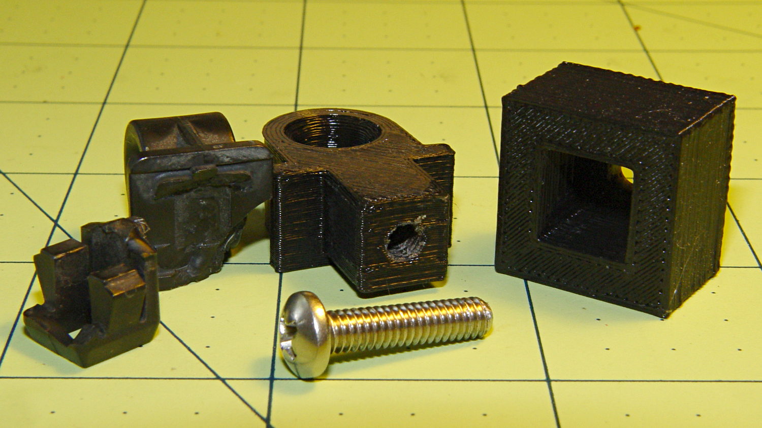
The general idea is that the screw puts the entire post under compression, giving it less temptation to shear at the deck line when I twist the rod a bit too far out of line. That 8-32 screw seemed entirely adequate to the task; a 10-32 screw would take up too much of the post for my liking.
Alas, it turns out that underneath the bulkhead’s top flange lies a metal plate surrounding the headlight that’s so close to the hole that the big blocky cap wouldn’t fit. So I slimmed the cap down to three thread widths and tried again, only to discover that the plate came that close to the edge of square hole.
However, there was a gap between the bottom of the bulkhead and the top of the plate, so I introduced pivot and cap to Mr Belt Sander, removed enough plastic to let the cap slide into the gap, then discovered the 8-32 screw head was just slightly too large to let the screw align with the post.
Another tweak to the model, based on actual measurements on the abused parts, produced the final version:
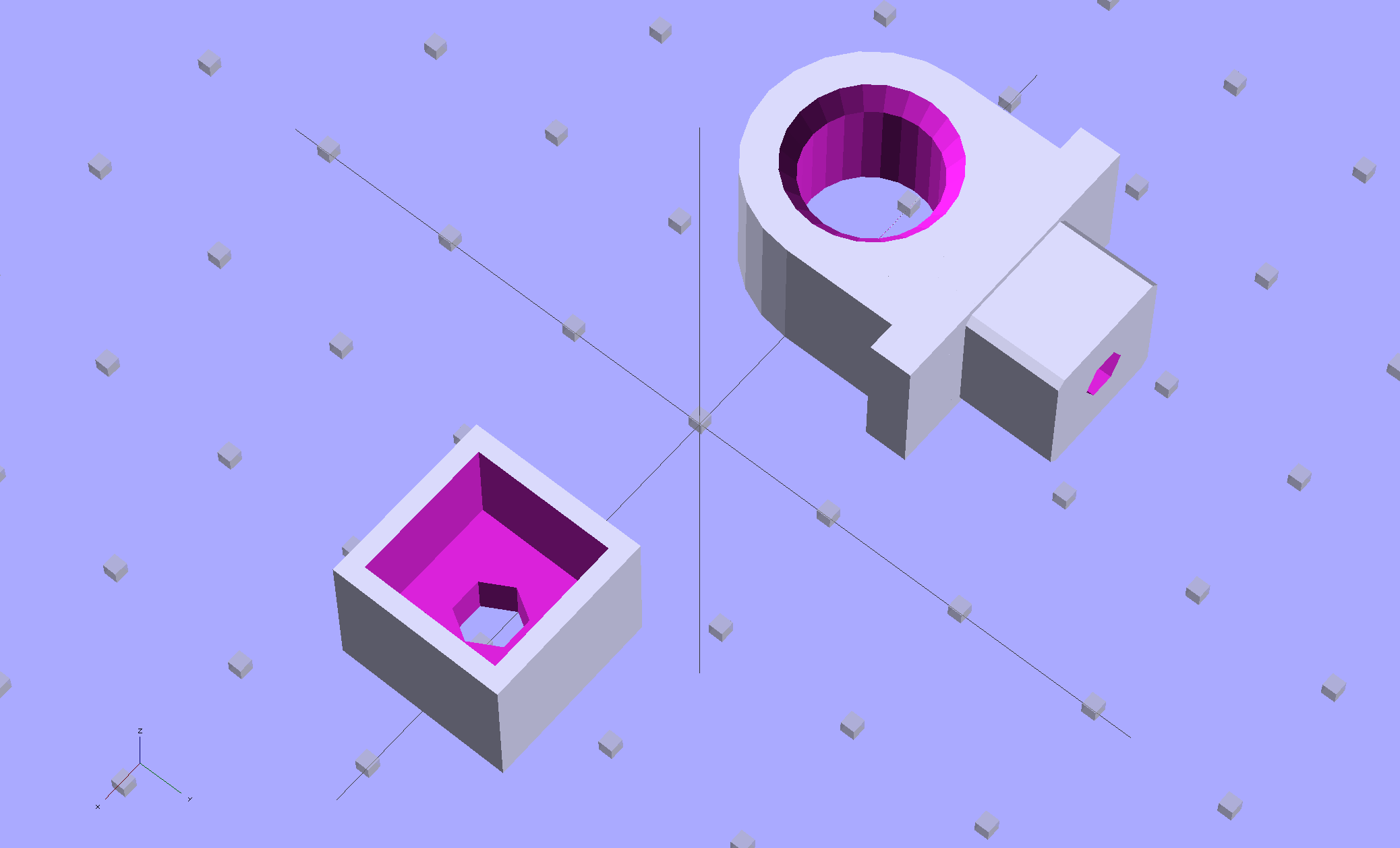
The rod hole has a nice bevel, there’s no fragile neck between the rod hole and the base flange, the solid post lies flat on the platform for EZ building, and there’s a slight offset between the post and the flange that eliminates the need for support material. Printing it lying down orients the filament paths around the hole and base, making the part stronger in the direction it needs the most strength.
I think the cap walls could be slightly thicker, but we’ll see how long the thing lasts…
A group photo of all the versions, lined up from left to right, shows the broken OEM part, the first blocky attempt, the slimmed-down and too-long version to the rear, the shorter version that actually fit, and a backup part for when that one breaks:
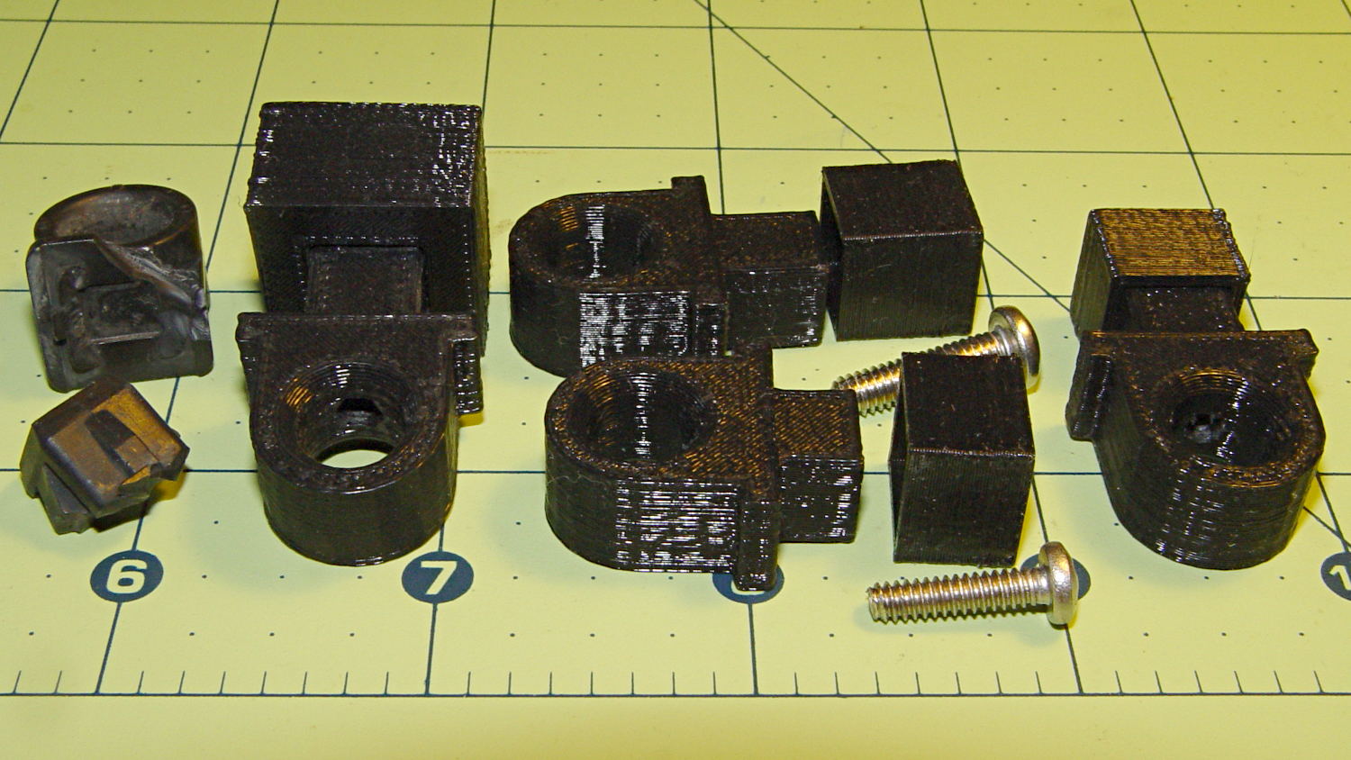
The sanded-down part held the hood open while I took that group picture. Here’s what it looks like under load:
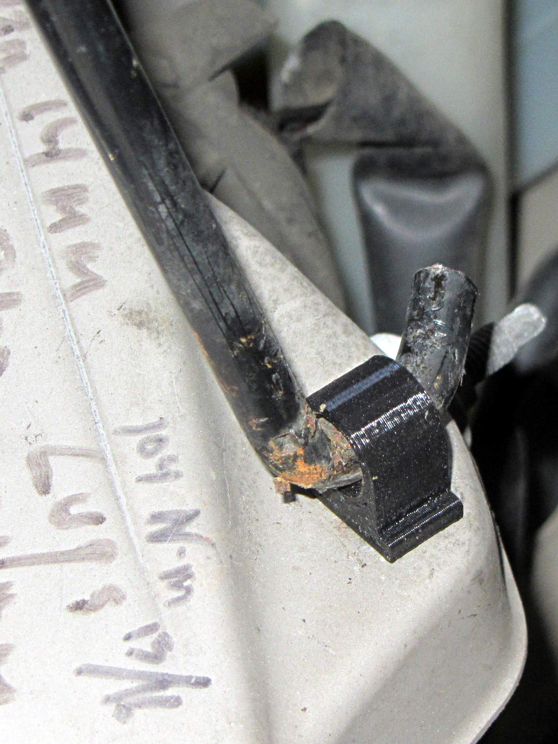
The scrawls on the bulkhead just in front of the pivot remind me of fluid levels, torques, and suchlike. The stud sticking out to the rear is a headlight aiming screw mounted in the plate that caused so much hassle; you’d think I’d have noticed it before starting this adventure, but noooo…
For what it’s worth, that’s rapid prototyping in action: three (and a half) iterations in quick succession, each getting closer to a goal that you (well, I) can’t quite define, but will recognize when it appears. Took about three hours over the course of two days.
I loves me my M2 3D printer…
(*) Indeed, the tires often take three miles to warm up their flat spots due to sitting in the garage for a week…
While reducing the clutter atop the Electronics Workbench, I ran off four more probe flange reinforcements, just so I’m ready for the next crunch:

They’re almost identical to the previous version, although I tweaked the taper to end slightly inside the cylindrical cup, thereby eliminating the coincident faces and leaving a minute rim that doesn’t matter:

Given that I’ve had the ‘scope for nigh onto two decades and have only broken one probe flange, I think four reinforcements will be a lifetime supply: with any luck, the scope will blow a capacitor before I do.
The OpenSCAD source code:
// Tek Scope Probe Flange
// Ed Nisley KE4ZNU November 2013

//- Extrusion parameters must match reality!
//  Print with 2 shells and 3 solid layers

ThreadThick = 0.20;
ThreadWidth = 0.40;

HoleWindage = 0.2;

Protrusion = 0.1;            // make holes end cleanly

function IntegerMultiple(Size,Unit) = Unit * ceil(Size / Unit);

//----------------------
// Dimensions

FlangeOD = 16.0;
FlangeID = 8.75;
FlangeThick = IntegerMultiple(1.25,ThreadThick);

DiskOD = FlangeOD + 4*ThreadWidth;
DiskThick = FlangeThick + 4*ThreadThick;

NumSides = 8*4;

//----------------------
// Useful routines

module PolyCyl(Dia,Height,ForceSides=0) {            // based on nophead's polyholes

Sides = (ForceSides != 0) ? ForceSides : (ceil(Dia) + 2);

FixDia = Dia / cos(180/Sides);

cylinder(r=(FixDia + HoleWindage)/2,
h=Height,
$fn=Sides);
}

module ShowPegGrid(Space = 10.0,Size = 1.0) {

Range = floor(50 / Space);

for (x=[-Range:Range])
for (y=[-Range:Range])
translate([x*Space,y*Space,Size/2])
%cube(Size,center=true);

}

//----------------------
// Build it

ShowPegGrid();

difference() {
union() {
translate([0,0,2*ThreadThick])
cylinder(r=DiskOD/2,h=DiskThick,$fn=NumSides);    // cylinder around flange

cylinder(r1=(DiskOD - 2*ThreadWidth)/2,                // flange reinforcing plate
r2=DiskOD/2,
h=(2*ThreadThick + Protrusion),
$fn=NumSides);
}
translate([0,0,(DiskThick - FlangeThick)])                // flange clearance
PolyCyl(FlangeOD,2*FlangeThick,NumSides);

translate([0,0,-DiskThick/2])                            // probe nose clearance
PolyCyl(FlangeID,2*DiskThick,NumSides);
}
This being leaf season, I just discovered that the recoil starter on the hulking 8 HP tangential leaf blower retracts very, very slowly. Having already started the engine, I did one pass around the yard with the pull cord dangling over the handlebar, but that’s not to be tolerated.
The starter mounts on the back of the motor with five screws, so removing it posed no problem at all. Removing the central screw released the friction clutch that helps extend the pawls, exposing the central boss that’s the combination hold-it-all-together point and gritty bearing for the rope spool:
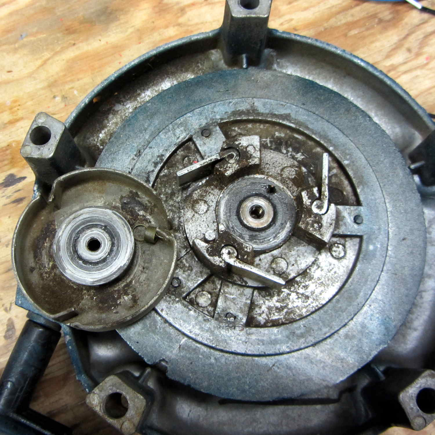
Pulling the rope turns the spool and extends the pawls that engage the crankshaft. After the motor starts, the pawls retract and none of that stuff moves, so there are no high-speed bearings and not much need for strength.
I brushed off some of the larger chunks, worked machine oil around the central post, wiped off & lubed the pawls, took the friction clutch apart & lightly lubed it, put everything back together, and the starter now works fine again; there may be too little friction in the clutch, but that’s in the nature of fine tuning.
The leaf blower Came With The House™ and dates back to the era when Kohler made cast-iron engine blocks. It runs lean on the oxygenated fuel that’s mandated for Dutchess County these days, so it now runs lightly choked.
Tip: before you yank the rope on a small engine, pull it slowly until the crankshaft stops turning freely, then let the rope retract. That positions the piston at the start of the compression stroke with the valves closed, so your next full-strength yank will do the most good.
Quite some time ago I manage to break the finger flange on one of my scope probes and, what with it being made of an un-glueable engineering plastic, a simple repair job failed quickly. It’s entirely round and a perfect lathe project, but … this is easier:

You can see remnants of that failed repair just below the fracture:

Some epoxy around the rim of the flange, plus filling the missing sector, looks about as grubby as you’d expect:
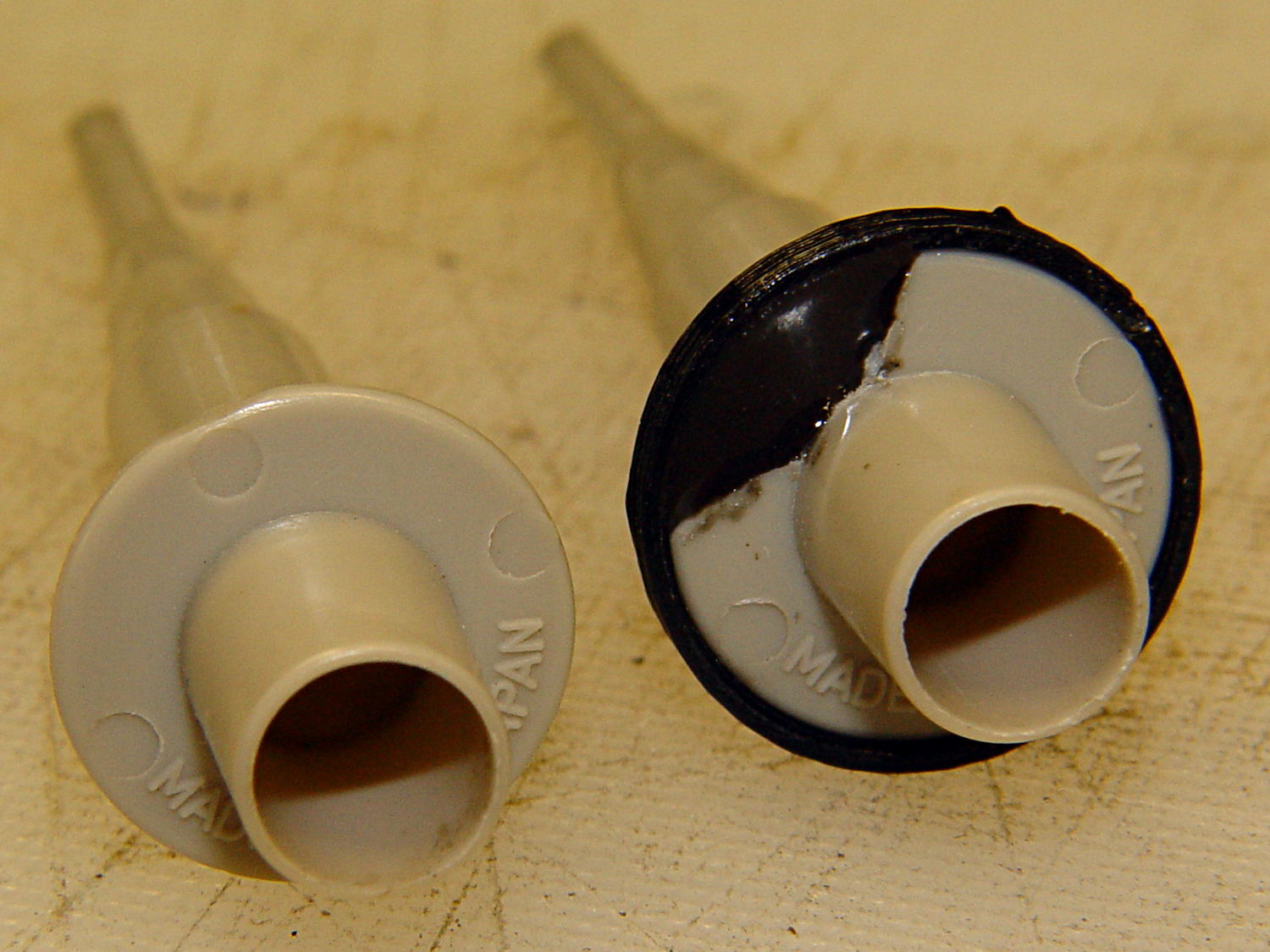
That’s a tiny zit at about 1 o’clock which came off with fingernail pressure.
From the business end, it actually looks pretty snappy:

I’m mildly tempted to preemptively reinforce the other probes…
The OpenSCAD source code joins two parts with coincident faces, but it worked out OK for once:
// Tek Scope Probe Flange
// Ed Nisley KE4ZNU November 2013

//- Extrusion parameters must match reality!
//  Print with 2 shells and 3 solid layers

ThreadThick = 0.25;
ThreadWidth = 0.40;

HoleWindage = 0.2;

Protrusion = 0.1;			// make holes end cleanly

function IntegerMultiple(Size,Unit) = Unit * ceil(Size / Unit);

//----------------------
// Dimensions

FlangeOD = 16.0;
FlangeID = 8.75;
FlangeThick = IntegerMultiple(1.25,ThreadThick);

DiskOD = FlangeOD + 4*ThreadWidth;
DiskThick = FlangeThick + 4*ThreadThick;

NumSides = 8*4;

//----------------------
// Useful routines

module PolyCyl(Dia,Height,ForceSides=0) {			// based on nophead's polyholes

  Sides = (ForceSides != 0) ? ForceSides : (ceil(Dia) + 2);

  FixDia = Dia / cos(180/Sides);

  cylinder(r=(FixDia + HoleWindage)/2,
           h=Height,
	   $fn=Sides);
}

module ShowPegGrid(Space = 10.0,Size = 1.0) {

  Range = floor(50 / Space);

	for (x=[-Range:Range])
	  for (y=[-Range:Range])
		translate([x*Space,y*Space,Size/2])
		  %cube(Size,center=true);

}

//----------------------
// Build it

ShowPegGrid();

	difference() {
		union() {
			translate([0,0,2*ThreadThick])
				cylinder(r=DiskOD/2,h=DiskThick,$fn=NumSides);			// main repair part
			cylinder(r1=(DiskOD - 2*ThreadWidth)/2,r2=DiskOD/2,h=2*ThreadThick,$fn=NumSides);
		}
		translate([0,0,(DiskThick - FlangeThick)])				// flange clearance
			PolyCyl(FlangeOD,2*FlangeThick,NumSides);
		translate([0,0,-DiskThick/2])
			PolyCyl(FlangeID,2*DiskThick,NumSides);
	}

