The Smell of Molten Projects in the Morning

Ed Nisley's Blog: Shop notes, electronics, firmware, machinery, 3D printing, laser cuttery, and curiosities. Contents: 100% human thinking, 0% AI slop.

Tag: Repairs

If it used to work, it can work again

  • AD8310 Log Amp Module: Corrected Input Circuit

    After puzzling over the AD8310 Log Amp module’s peculiar frequency response, I hacked up the front end circuitry to match the data sheet’s recommended layout:

    AD8310 Log Amp module - revised
    AD8310 Log Amp module – revised

    Given the intended LF crystal-measurement application, a hulking 51 Ω metal film resistor sprawled across the ground plane will work just fine. All three ceramic caps measure a bit under 1 µF; I intended to solder the input caps atop the existing 10 nF caps, but that didn’t work out well at all.

    I should harvest the InLo SMA connector to prevent anyone from mistaking it for an actual input.

    With that in place, the log amp output makes more sense:

    AD8310 - modified - 100 kHz 150 MHz - 0 dB atten
    AD8310 – modified – 100 kHz 150 MHz – 0 dB atten

    That trace tops out at 150 MHz, not the previous 500 MHz, but now the response is flat all the way out. The log amp generates plenty of hash when the tracking generator isn’t producing a valid signal.

    The 60 kHz response looks different:

    AD8310 - modified - 60 kHz 1Vpp
    AD8310 – modified – 60 kHz 1Vpp

    So it’s really the log amp response to the absolute value of the sine wave (or, more accurately, to the sine wave re-zeroed around Vcc/2), with minimum output at the input’s zero crossings. At 500 mV/div, the log amp says the input varies by 42 dB = 1000 mV/(24 mV/dB), which might actually be about right for a zero-crossing (or zero-approaching absolute value of a) signal; logarithms don’t deal well with zeros.

    The AD8310 datasheet  and AN-691 suggest the 2.5 V output corresponds to +10 dBm = 12.5 Vrms input, which flat-out isn’t the case. However, the actual 500 mVpeak = 350 mVrms input is 2.5 mW = +4 dBm, so maybe it’s within spitting distance of being right.

    AN-691 recommends 10 µF input caps for “low frequency” use, showing results down to 20 Hz; 1 µF seems to get the circuit close enough to the goal for use near 60 kHz.

    It also recommends a cap on the BFIN pin (pin 6) to reduce the output stage bandwidth = “video bandwidth” and improve the overall accuracy, which remains to be done. The datasheet suggests rolling VBW off at 1/10 the minimum input frequency, which would be around 3 kHz for use with 32.768 kHz crystals. The equation, with reference to the internal 3 kΩ bias resistor:

    CFILT = 1/(2π 3 kΩ VBW) – 2.1 pF = 18 nF

    For a bit more margin, 1 kHz would require 56-ish nF.

    The PCB has a convenient pair of pads labeled C6 for that capacitor. This may require protracted rummaging in the SMD capacitor stash.

    Rolling off the VBW should reduce the hash on the 100 kHz end of the frequency sweep and filter the 60 kHz response down to pretty much a DC level.

    Applying the 10 dB and 20 dB SMA attenuators to the input from the tracking generator and recording the log amp output voltage produces this useful table:

    AD8310 Log Amp - mods and log response
    AD8310 Log Amp – mods and log response

    With the terminating resistor on the correct side of the input caps, the log amp seems to be working the way it should, with an output varying a bit under the nominal 24-ish mV/dB over a 30 dB range.

    We need caps! Lots of caps!

    A quick search with the obvious keywords suggests nobody else has noticed how these modules work over a reasonable bandwidth. Maybe I’m the first person to use them in the LF band?

  • Kindle Fire Power Button: Some Things Don’t Last

    Once again, the single moving part on my first-generation Kindle Fire stopped working. As before, the switch contacts accumulated enough fuzz & contamination to prevent any current flow, but this time the (soft) solder joints attaching the switch body to the PCB failed:

    Kindle Fire power switch - failed anchor
    Kindle Fire power switch – failed anchor

    My joint cleaning & fluxing wasn’t up to contemporary standards, as shown by the obviously un-fused footprints left in the upper pads:

    Kindle Fire power switch - failed anchor joints
    Kindle Fire power switch – failed anchor joints

    The switch frame seems to be unplated steel, which shouldn’t be an excuse.

    So I dismantled the switch, cleaned the contacts and tactile bump plate, put it all back together, and did a much better job of surface preparation:

    Kindle Fire power switch - rebuilt - right anchor
    Kindle Fire power switch – rebuilt – right anchor

    The other joint:

    Kindle Fire power switch - rebuilt - left anchor
    Kindle Fire power switch – rebuilt – left anchor

    And, for completeness, the switch leads:

    Kindle Fire power switch - rebuilt - switch pads
    Kindle Fire power switch – rebuilt – switch pads

    I don’t like the way the joint on the right looks, either, but we’ll see how long the whole affair holds together.

    This may be the last time I can repair the Kindle, as a bypass cap came loose while I was working on the PCB, the screen has been accumulating dust at an increasing pace, and several latches securing the back of the case have cracked.

    Methinks it’s getting on time for a new pocketable memory device; if only Pixel XL phablets had a bigger screen and didn’t cost night onto a kilobuck.


  • Tour Easy Front Fender Clip: Heatshrink

    So: jouncing over the larg(er) potholes / pavement discontinuities / debris on the roads around here wobbulates the front fender enough to pull the stays out of those tidy 18 mm = 6 diameter deep sockets on the fender clip.

    Perhaps a generous application of heatshrink tubing will help:

    Tour Easy Front Fender Clip - heatshrink hack
    Tour Easy Front Fender Clip – heatshrink hack

    Waving a heat gun around a 3D printed part seems fraught with peril, even with PETG’s glass transition temperature around 80 °C = 175 °F, as ordinary polyolefin tubing shrinks at 140-ish °C. Aiming the hot air stream more-or-less away from the clip (and the tire!) carried the day. PLA would surely have gotten bendy.

    The proper solution surely involves screw clamps and suchlike. I really dislike fiddly hardware: I hope this hack survives.

  • Garage Door Openers: Pity the Color Blind

    The small garage door opener I tote around in the Tour Easy’s underseat bag failed after many years of exposure to the elements, so I paid a few bucks more for a cheap replacement in order to get fast delivery from a (US!) eBay supplier:

    Garage door opener remote controls
    Garage door opener remote controls

    For whatever it’s worth, before buying the replacement I tried:

    • Cleaning the battery contacts
    • Installing a new CR2032 battery
    • Programming the hitherto-unused buttons to open the door

    The remote control would occasionally work, but none of the “repairs” made much difference; I suspect corrosion hidden under the components or cracked solder joints.

    The eBay item description clearly, if inarticulately, specifies the compatibility requirement:

    key chain remote control
    compatible for purple learn button

    So I trotted out to the garage and inspected the button:

    Sears Garage Door Opener - purple button
    Sears Garage Door Opener – purple button

    Looks purple to me, but, being that type of guy, I also read the adjacent instruction sticker:

    Sears Garage Door Opener - instructions
    Sears Garage Door Opener – instructions

    Nobody, nobody, maintains the documentation. [sigh]

    I figured if they went to all the trouble of ordering a bazillion switches with purple caps, then the PCB surely holds the corresponding RF filters & firmware & whatever else that button signifies.

    Seeing as how we have exactly one garage door opener and no lights or other doodads, I told the opener to obey both the 1 and 2 buttons, thereby dramatically reducing the dexterity required to open the door while pedaling up the driveway. The opener can remember an unspecified number of transmitters, so I didn’t go for all four buttons.

  • Tour Easy Front Fender Clip

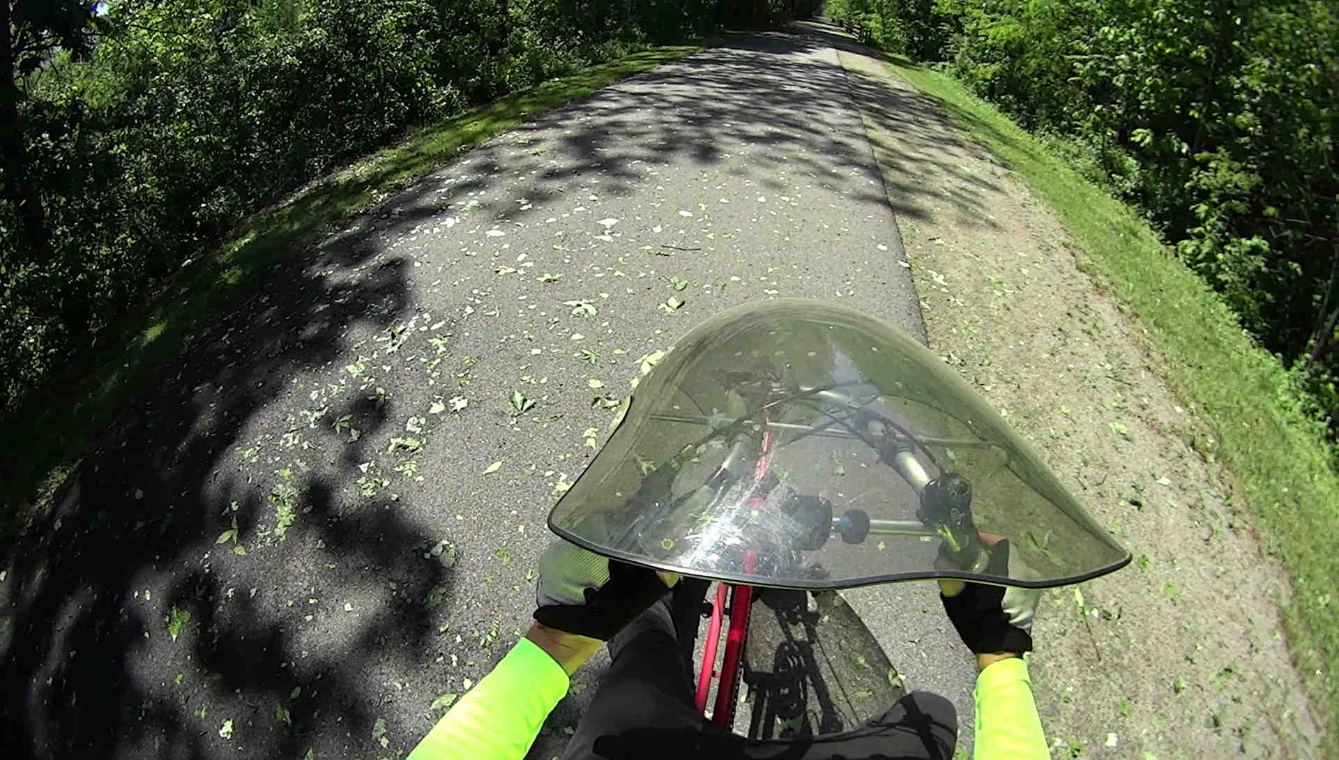
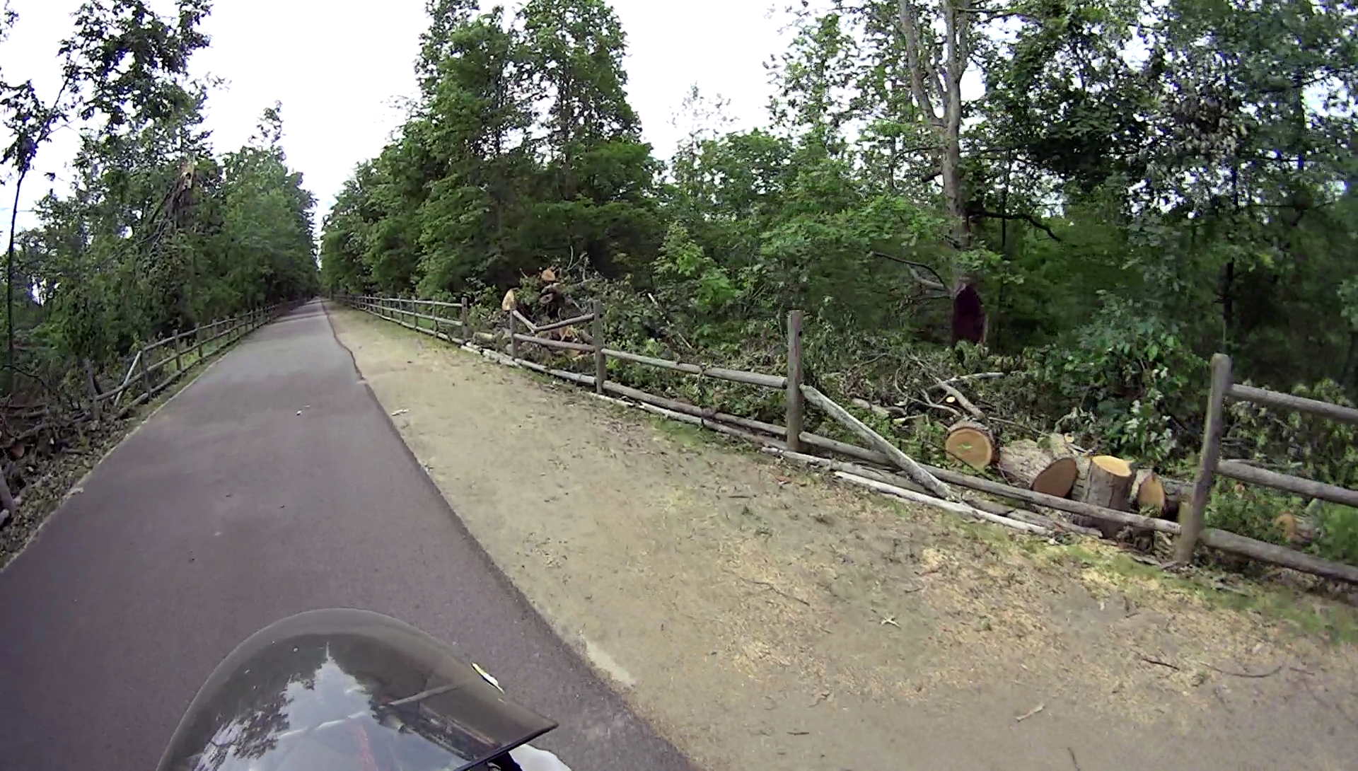
    We rode the Feeder Canal trail during a recent bike vacation in exotic Glens Falls NY:

    Feeder Canal Park Trail - Branches
    Feeder Canal Park Trail – Branches

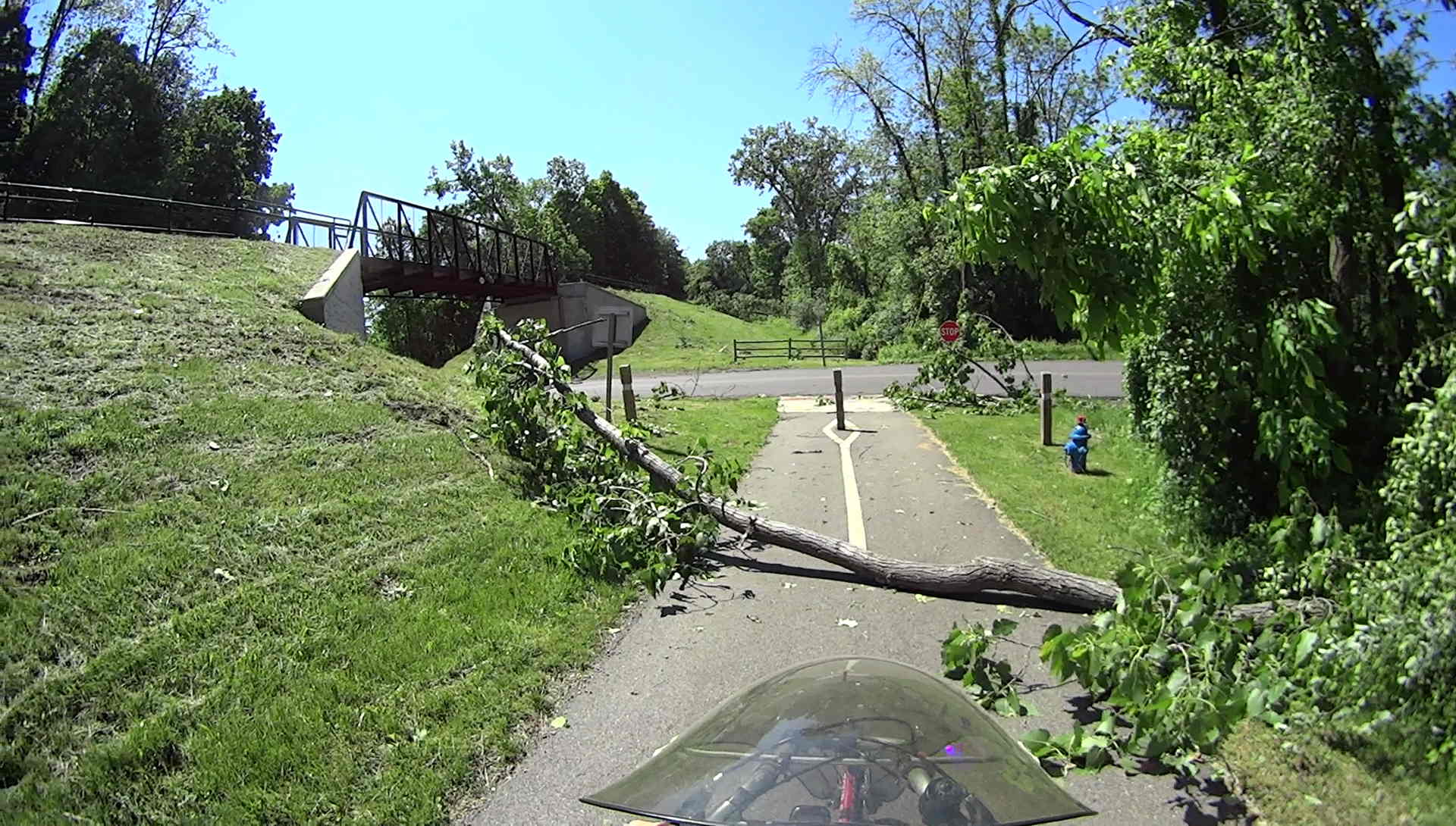
    The numerous downed branches along the trail and countless twigs on the trail came from a brush-clearing operation:

    Feeder Canal Park Trail - Brush Clearing
    Feeder Canal Park Trail – Brush Clearing

    As luck would have it, a twig snagged between my front tire and fender, snapping the clips holding the fender in place:


    Tour Easy front fender mount breakage
    Tour Easy front fender mount breakage

    Should it not be obvious, each ferrule formerly had two parallel jaws (on the left) gripping the fender, with the tiny screw digging into the fender. I affixed the fender to the broken clips with copious amounts of duct tape and we continued the mission.

    It should be obvious why those ferrules are not suitable for 3D printing.

    However, with the recent rear fender clip serving as inspiration, this didn’t take long:

    Tour Easy - Front Fender Clip - Slic3r
    Tour Easy – Front Fender Clip – Slic3r

    The front fender fits a 20 inch wheel and is somewhat wider and flatter than the rear fender (I think they bent the same plastic strip around a smaller mandrel), so I did a quick copy-and-paste hack job on the OpenSCAD source code, rather than trying to parameterize the daylights out of the previous model.

    The posts around the wire stays are 6 diameters deep and reamed to fit; the stays won’t be flopping around even without fiddly mechanical hardware retaining them. The holes extend about halfway into those posts to mimic the dimensions of the original ferrules.

    All of us can predict where the next break will occur, right? That’s OK: I want this to break, instead of wrecking the fender, so the only question is how much abuse those simple joints can withstand. The printing orientation wraps the perimeter threads from the posts around the clip, making it about a strong as it can be.

    The ferrules should splay outward by a few degrees to match the angle from the fender to the fork eyelets, but that’s in the nature of fine tuning.

    The arch accommodates a strip of double-sided foam tape holding the clip in place along the fender curve, with those cute little hooks capturing the fender to keep the tape in compression:

    Tour Easy Front Fender Clip - installed
    Tour Easy Front Fender Clip – installed

    I really must get some black foam tape …

    The picture shows the fender sitting well away from the tire, due to the upper fender mount bending in response to the splash flap snagging on curbs and random debris; the wire stays didn’t seat completely into the posts.

    The extender I made during the cracked fork episode remained perfectly straight, though:

    Tour Easy - new fork - fender extender
    Tour Easy – new fork – fender extender

    So I re-bent the upper fender mount (not the extender!) to its original angle, thereby moving the bottom of the fender much closer to the tire. Now the stays seat fully, the clip holds the fender firmly in place with no rattles, and it’s all good.

    The OpenSCAD source code as a GitHub Gist:

    // Tour Easy front fender clip
    // Ed Nisley KE4ZNU April 2017
    Layout = "Clip"; // Build Profile Ferrule Clip
    //- Extrusion parameters must match reality!
    ThreadThick = 0.25;
    ThreadWidth = 0.40;
    HoleWindage = 0.2;
    Protrusion = 0.1; // make holes end cleanly
    inch = 25.4;
    function IntegerMultiple(Size,Unit) = Unit * ceil(Size / Unit);
    //———————-
    // Dimensions
    // special case: fender is exactly half a circle!
    FenderC = 51.0; // fender outside width = chord
    FenderM = 21.0; // height of chord
    FenderR = (pow(FenderM,2) + pow(FenderC,2)/4) / (2 * FenderM); // radius
    echo(str("Fender radius: ", FenderR));
    FenderD = 2*FenderR;
    FenderA = 2 * asin(FenderC / (2*FenderR));
    echo(str(" … arc: ",FenderA," deg"));
    FenderThick = 2.5; // fender thickness, assume dia of edge
    ClipHeight = 15.0; // top to bottom, ignoring rakish tilt
    ClipThick = 3.0; // thickness of clip around fender
    ClipD = FenderD; // ID of clip against
    ClipSides = 4 * 8; // polygon sides around clip circle
    BendReliefD = 2.5; // bend arch diameter
    BendReliefA = 2/3 * FenderA/2; // … angle from dead ahead
    BendReliefCut = 1.0; // factor to thin outside of bend
    ID = 0;
    OD = 1;
    LENGTH = 2;
    StayDia = 3.3; // fender stay rod diameter
    StayOffset = 23.0; // stay-to-fender distance
    StayAngle = -5; // angle from stay to fender
    FerruleSides = 2*4;
    Ferrule = [StayDia,3*FenderThick/cos(180/FerruleSides),6*StayDia + StayOffset]; // ID = stay rod OD
    //———————-
    // Useful routines
    module PolyCyl(Dia,Height,ForceSides=0) { // based on nophead's polyholes
    Sides = (ForceSides != 0) ? ForceSides : (ceil(Dia) + 2);
    FixDia = Dia / cos(180/Sides);
    cylinder(r=(FixDia + HoleWindage)/2,
    h=Height,
    $fn=Sides);
    }
    //———————-
    // Clip profile around fender
    // Centered on fender arc
    module Profile(HeightScale = 1) {
    linear_extrude(height=HeightScale*ClipHeight,convexity=5) {
    difference() {
    offset(r=ClipThick) // outside of clip
    union() {
    circle(d=ClipD,$fn=ClipSides);
    for (i=[-1,1])
    rotate(i*BendReliefA) {
    translate([ClipD/2 + BendReliefD/2,0,0])
    circle(d=BendReliefD,$fn=6);
    }
    }
    union() { // inside of clip
    circle(d=ClipD,$fn=ClipSides);
    for (i=[-1,1])
    rotate(i*BendReliefA) {
    translate([ClipD/2 + BendReliefCut*BendReliefD/2,0,0])
    circle(d=BendReliefD/cos(180/6),$fn=6);
    translate([ClipD/2,0,0])
    square([BendReliefCut*BendReliefD,BendReliefD],center=true);
    }
    }
    translate([(FenderR – FenderM – FenderD/2),0]) // trim ends
    square([FenderD,2*FenderD],center=true);
    }
    for (a=[-1,1]) // hooks around fender
    rotate(a*(FenderA/2))
    translate([FenderR – FenderThick/2,0]) {
    difference() {
    rotate(1*180/12)
    circle(d=FenderThick + 2*ClipThick,$fn=12);
    rotate(1*180/8)
    circle(d=FenderThick,$fn=8);
    rotate(a * -90)
    translate([0,-2*FenderThick,0])
    square(4*FenderThick,center=false);
    }
    }
    }
    }
    //———————-
    // Ferrule body
    module FerruleBody() {
    translate([0,0,Ferrule[OD]/2 * cos(180/FerruleSides)])
    rotate([0,-90,0]) rotate(180/FerruleSides)
    difference() {
    cylinder(d=Ferrule[OD],h=Ferrule[LENGTH],$fn=FerruleSides,center=false);
    translate([0,0,StayOffset + Protrusion])
    PolyCyl(Ferrule[ID],Ferrule[LENGTH] – StayOffset + Protrusion,FerruleSides);
    }
    }
    //———————-
    // Generate entire clip at mounting angle
    module FenderClip() {
    union() {
    translate([FenderR,0,0])
    difference() { // angle and trim clip
    rotate([0,StayAngle,0])
    translate([-(FenderR + ClipThick),0,0])
    Profile(2); // scale upward for trimming
    translate([0,0,-ClipHeight]) // trim bottom
    cube(2*[FenderD,FenderD,ClipHeight],center=true);
    translate([0,0,ClipHeight*cos(StayAngle)+ClipHeight]) // trim top
    cube(2*[FenderD,FenderD,ClipHeight],center=true);
    }
    for (j = [-1,1])
    translate([Ferrule[OD]*sin(StayAngle),j*(FenderR – FenderThick + FenderThick/2),0])
    FerruleBody();
    }
    }
    //———————-
    // Build it
    if (Layout == "Profile") {
    Profile();
    }
    if (Layout == "Ferrule") {
    FerruleBody();
    }
    if (Layout == "Clip") {
    FenderClip();
    }
    if (Layout == "Build") {
    FenderClip();
    }


  • Some Things Last: 100 W Incandescent Bulb

    The light switch for our attic turns on a single ceramic socket at the top of the stairs. The bulb burned out a few days ago:

    Long-lasting 100 W Incandescent Bulb
    Long-lasting 100 W Incandescent Bulb

    To the best of my knowledge, that bulb has been in service since we moved in almost two decades ago. Most likely, it was installed when the house was built in 1955, because it matches several new-old-stock bulbs in a battered box that Came With The House™.

    To be fair, the attic light doesn’t see much service, but … it’s been a great cost-performer!

    The attic temperatures range from well below 0 °F in the winter to well above 120 °F in the summer, so it’s no place for CFL or LED bulbs. I swapped in a 60 W bulb from my heap, although I doubt it’ll be good for another half-century.

  • Planet Bike SuperFlash Case: PUSH Fatigue

    The blinky light on Mary’s bike became intermittent and, after a week or two, I figured out why:

    Planet Bike Superflash - fatigued PUSH
    Planet Bike Superflash – fatigued PUSH

    The white plastic case has a thin section labeled PUSH over the switch. After five years of exposure to the sun (it faces upward on her bike) and upwards of 2000 pushes (5 years x 200 rides/year x 2 pushes/ride), the edges of that little plate cracked, it slipped inward, and jammed the switch button.

    I swapped it for the one on my bike, which mounts with the switch downward and has seen much less use since I began running the Fly 6 rear camera + blinky light, and it was all good.

    The fractured plate slid snugly back in place, a few drops of IPS 3 solvent-bonded the broken edges, and a snippet of good 3M electrical tape inside the case should provide a bit of reinforcement:

    Planet Bike Superflash - reinforced cover
    Planet Bike Superflash – reinforced cover

    It’s now on my bike, just in case it’s needed.

    That was easy …