Ed Nisley's Blog: Shop notes, electronics, firmware, machinery, 3D printing, laser cuttery, and curiosities. Contents: 100% human thinking, 0% AI slop.
Anything would be better than just taping some gel filters to the front of the bare photodiode package:
Laser output – photodiode kludge
Right?
I heaved the slab of ½ inch black acrylic left over from the Totally Featureless (WWVB) Clock into the laser cutter and, two passes at 90% power later, had a somewhat lumpy 32 mm donut with an 11 mm hole in the middle. Because acrylic is opaque to the IR light from a CO₂ laser (which is why it cuts so well) and black acrylic is opaque to visible light (which is what the photodiode is designed for), this is at least as good as an aluminum housing and much easier to make.
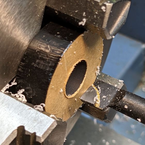
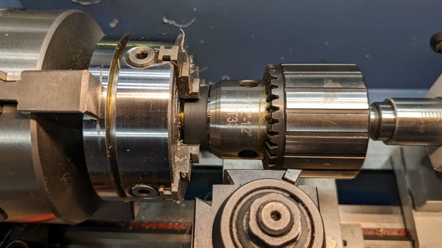
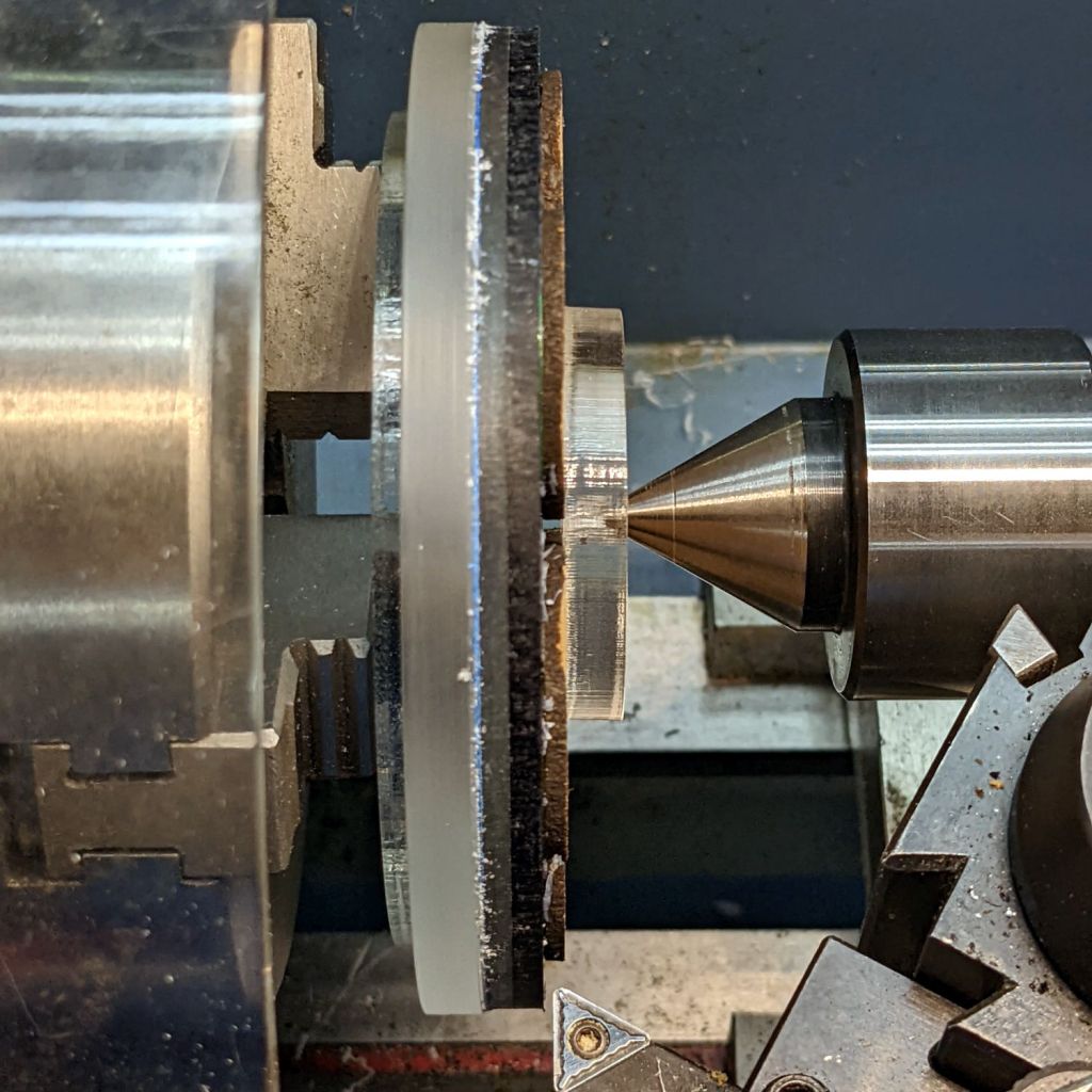
Chuck the donut into Tiny Lathe and bore out the hole:
PIN-10D photodiode filter holder – boring ID
When it’s a snug fit to ½ inch brass tube (about the same size as the photodiode’s active area), flip it around, and bore the other size out to fit the photodiode case.
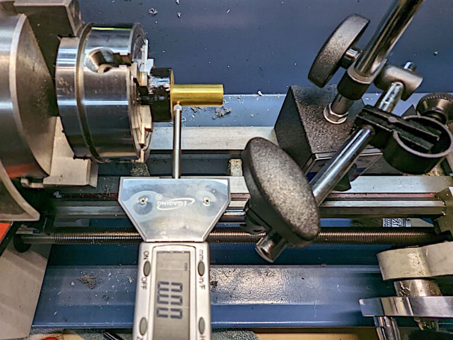
Ram the tube in place, grab the large recess, and center the tube:
[Edit: Got that backwards: I bored the big recess first.]
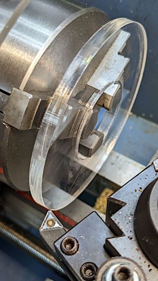
Skim most of the OD down, then, because I am a dolt forgot to put a spacer in there, flip it around again, get it running true (the chuck aligns the flat side):
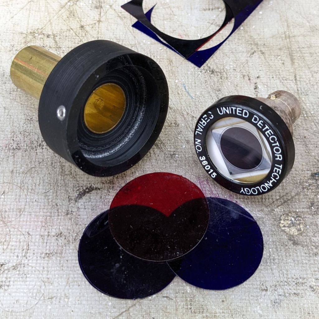
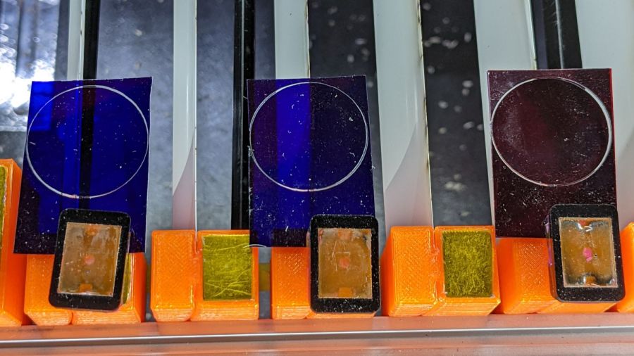
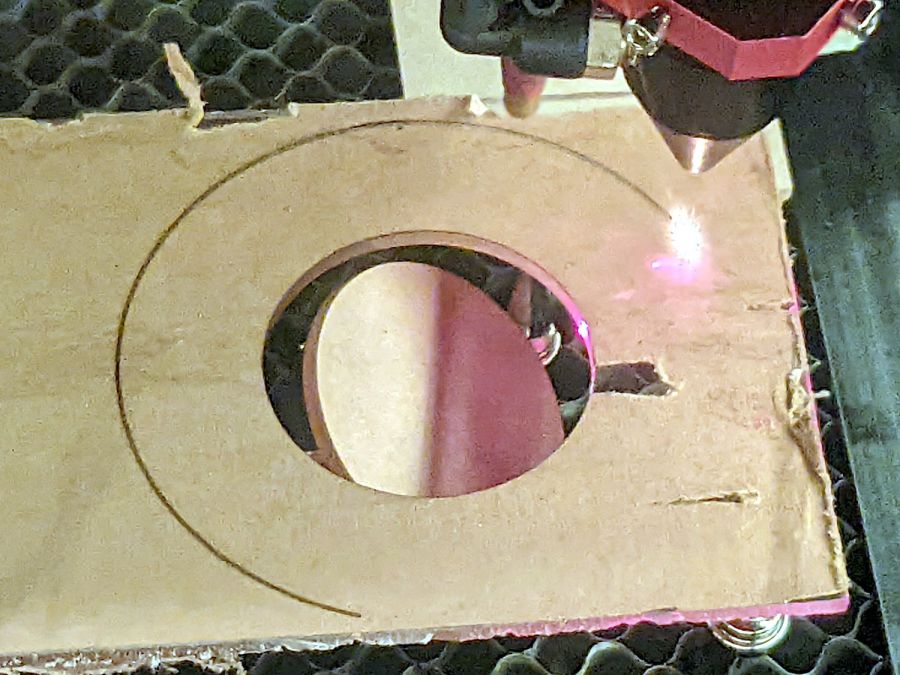
Even though they’re pretty much transparent to thermal IR, a focused IR laser beam cuts them just fine. The little tab at 6 o’clock (remember round clocks with hands?) keeps the cut circle from falling out.
Drill & tap for an M3 setscrew to hold the photodiode in place:
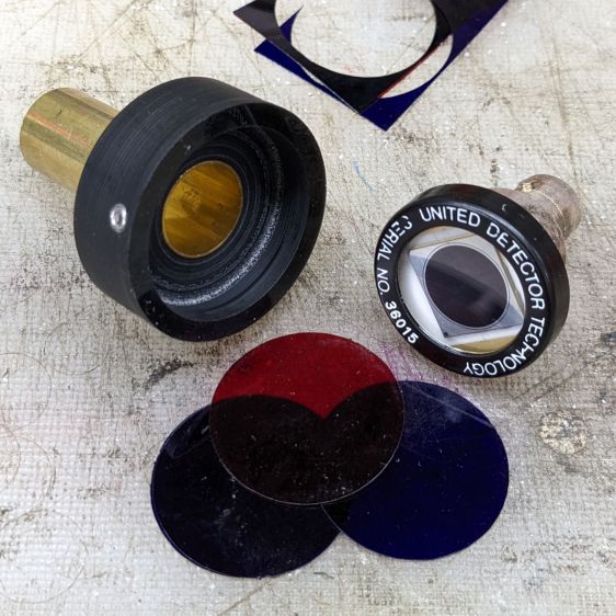
PIN-10D photodiode filter holder – parts
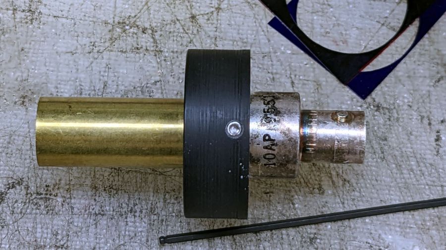
Put them all together:
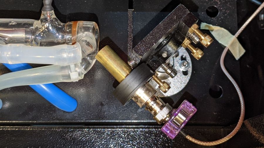
PIN-10D photodiode filter holder – assembled
I must conjure a better mount for the thing, because this is way too precarious:
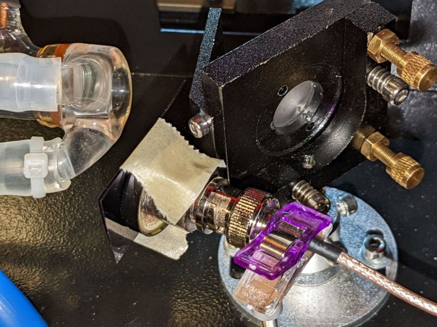
PIN-10D photodiode filter holder – test install
Early results suggest it works better than the previous hack job, without ambient light sneaking around the edges of the filter pack.
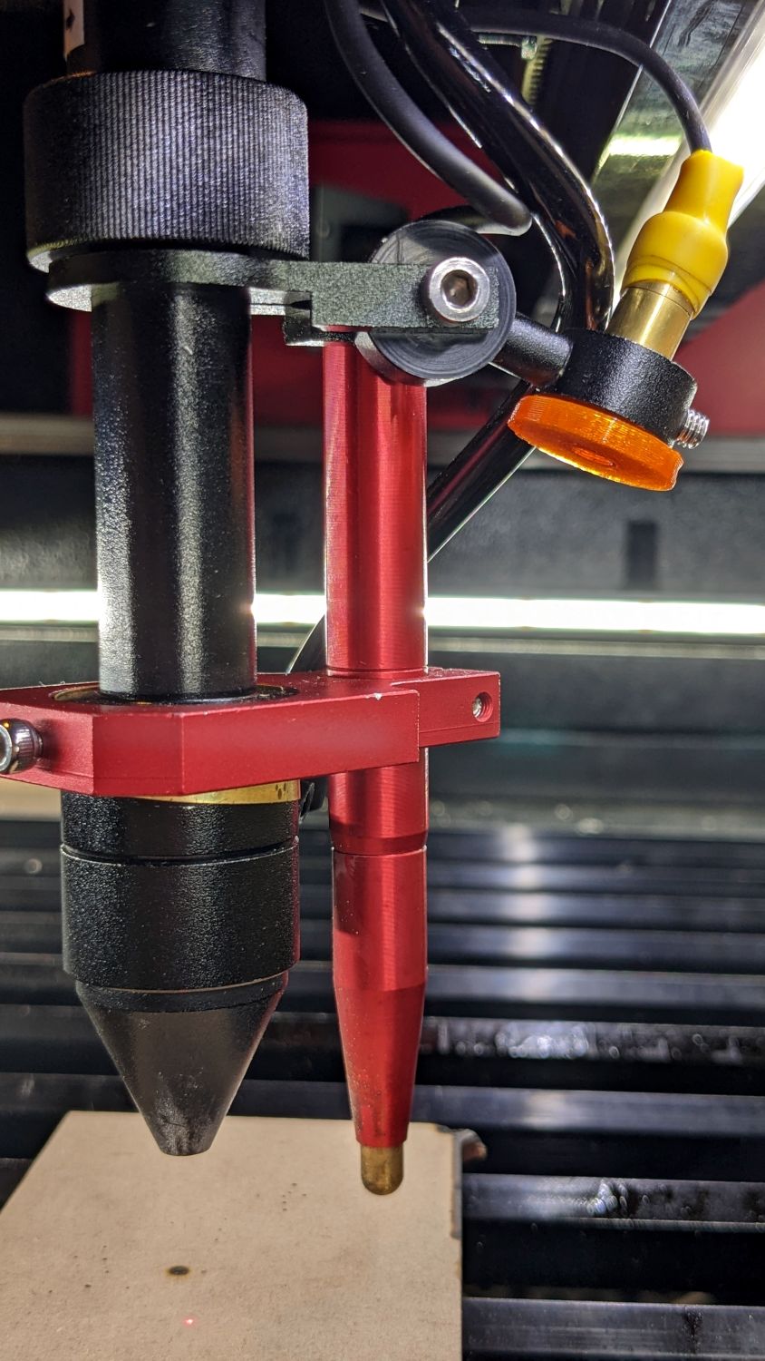
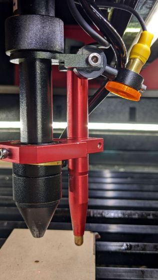
The red-dot pointer on the OMTech laser cutter has the same problem as my laser aligner for the Sherline mill: too much brightness creating too large a visual spot. In addition, there’s no way to make fine positioning adjustments, because the whole mechanical assembly is just a pivot.
The first pass involved sticking a polarizing filter on the existing mount while I considered the problem:
OMTech red dot pointer – polarizing filter installed
The red dot pointer module is 8 mm OD and the ring is 10 mm ID, but you will be unsurprised to know the laser arrived with the module jammed in the mount with a simple screw. Shortly thereafter, I turned the white Delrin bushing on the lathe to stabilize the pointer and installed a proper setscrew, but it’s obviously impossible to make delicate adjustments with that setup.
Making the polarizing filter involves cutting three circles:
OMTech red dot pointer – polarizing filter
Rotating the laser module in the bushing verified that I could reduce the red dot to a mere shadow of its former self, but it was no easier to align.
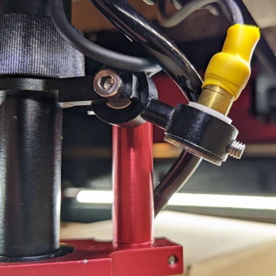
Replacing the Delrin bushing with a 3D printed adjuster gets closer to the goal:
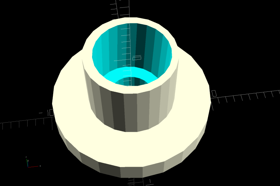
Pointer fine adjuster – solid model
Shoving a polarizing filter disk to the bottom of the recess, rotating the laser module for least brightness, then jamming the module in place produces a low-brightness laser spot.
The 8 mm recess for the laser module is tilted 2.5° with respect to the Y axis, so (in principle) rotating the adjuster + module (using the wide grip ring) will move the red dot in a circle:
Improved red-dot pointer – overview
The dot sits about 100 mm away at the main laser focal point, so the circle will be about 10 mm in diameter. In practice, the whole affair is so sloppy you get what you get, but at least it’s more easily adjusted.
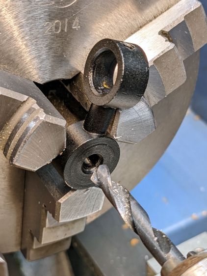
The M4 bolt clamping the holder to the main laser tube now goes through a Delrin bushing. I drilled out the original 4 mm screw hole to 6 mm to provide room for the bushing:
Improved red-dot pointer – drilling bolt hole
The bushing has a wide flange to soak up the excess space in the clamp ring:
Improved red-dot pointer – turning clamp bushing
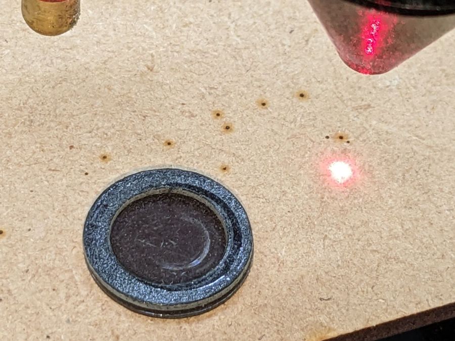
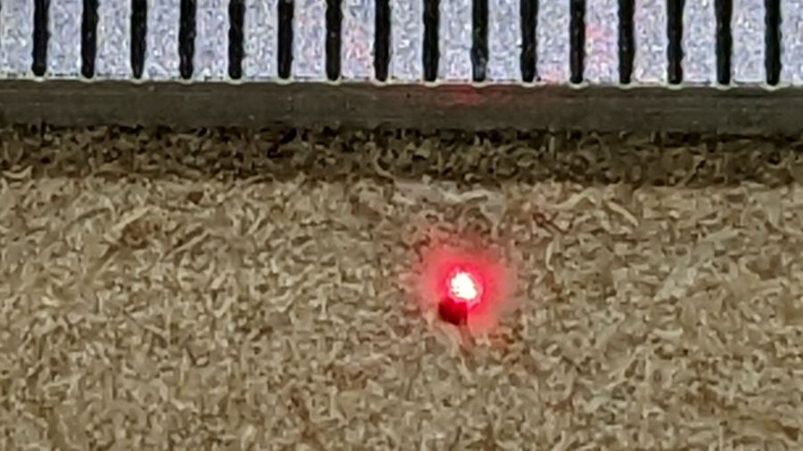
With all that in place, the dimmer dot is visually about 0.3 mm in diameter:
Improved red-dot pointer – offset
The crappy image quality comes from excessive digital zoom. The visible dot on the MDF surface is slightly larger than the blown-out white area in the image.
The CO₂ laser hole is offset from the red laser spot by about 0.3 mm in both X and Y. Eyeballometrically, the hole falls within the (dimmed) spot diameter, so this is as good as it gets. I have no idea how durable the alignment will be, but it feels sturdier than it started.
Because the red dot beam is 25° off vertical, every millimeter of vertical misalignment (due to non-flat surfaces, warping, whatever) shifts the red dot position half a millimeter in the XY plane. You can get a beam combiner to collimate the red dot with the main beam axis, but putting more optical elements in the beam path seems like a Bad Idea™ in general.
This file contains hidden or bidirectional Unicode text that may be interpreted or compiled differently than what appears below. To review, open the file in an editor that reveals hidden Unicode characters.
Learn more about bidirectional Unicode characters
Every now and again, an upshift to the large chainring on my Tour Easy would go awry and drop the chain off the outside, where it would sometimes jam between the pedal crank and the spider. In the worst case the flailing chain would also jam in the TerraCycle idler, but I fixed that a while ago.
Contemporary chainrings (i.e., anything made since the trailing decades of the last millennium) generally have a chain drop pin positioned against the crank specifically to prevent such chain jamming.
Making a chain drop pin is no big deal if you’ve got a lathe and an M4 tap:
Tour Easy – DIY Chain Drop pin
A closer look:
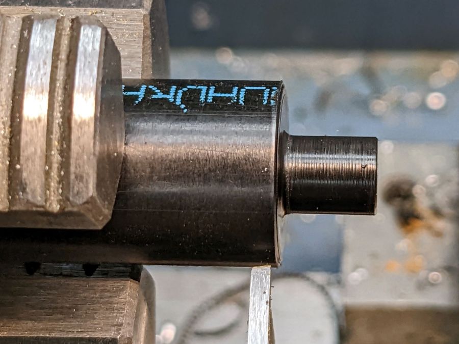
Tour Easy – DIY Chain Drop pin – detail
That’s a 10 mm length of 5/16 inch brass rod drilled with a recess to fit the head of a 10 mm M4 socket-head cap screw.
The pin should be a micro-smidgen shorter, as it just touches the crank, but, if anything, moving the chainring inward by one micro-smidgen improved the upshifts and I’m inclined to go with the flow.
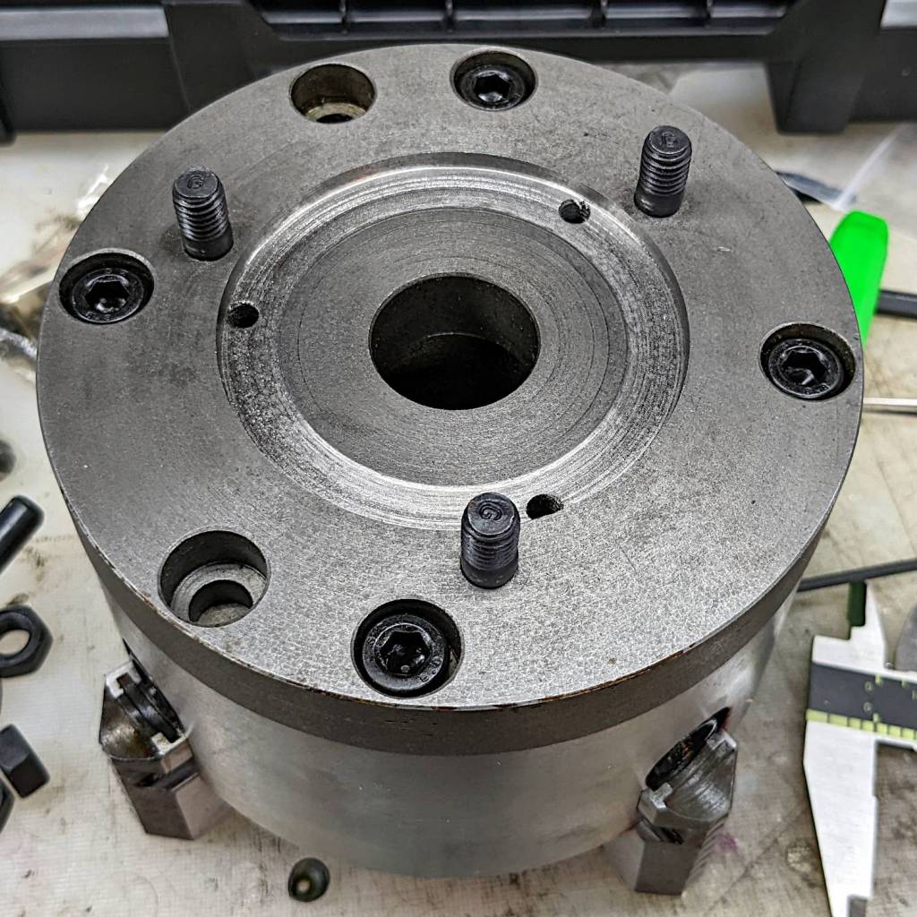
The kludge required to trim the coaster rims disturbed the silt enough to reveal a long-lost 5 inch 4 jaw chuck that fit neither the old South Bend lathe nor the new mini-lathe. In any event, the chuck does have an adapter plate on its backside, it’s just not the correct adapter plate for the spindle on my mini-lathe.
Making it fit required enlarging an existing recess to fit the spindle plate, a straightforward lathe job with the plate grabbed in the 3 jaw chuck’s outer jaws:
5 inch 4 jaw chuck – boring spindle recess
Carbide inserts don’t handle interrupted cuts very well, but sissy cuts saved the day. The plate is kinda-sorta cast iron, so the “chips” are dust and a vacuum snout reduces the mess; you can see some chips inside the bore.
A faceplate for the mini-lathe lathe located three holes matching the spindle plate, after I noticed the amazing coincidence of both parts having 26 mm bores. Making an alignment tool from a scrap of 3/4 inch (!) Schedule 40 PVC pipe was an easy lathe job:
5 inch 4 jaw chuck – adapter plate alignment
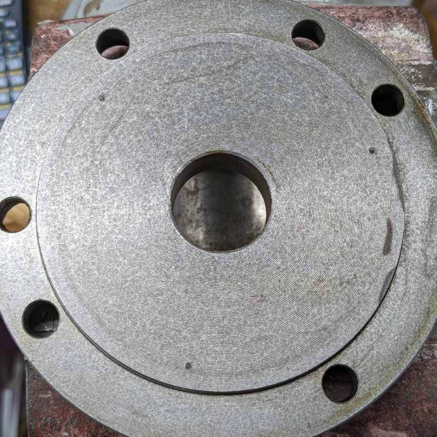
Transfer-punching those holes produced pips on the chuck side of the adapter plate:
5 inch 4 jaw chuck – spindle bolt spotting
I thought about freehanding the holes, but came to my senses:
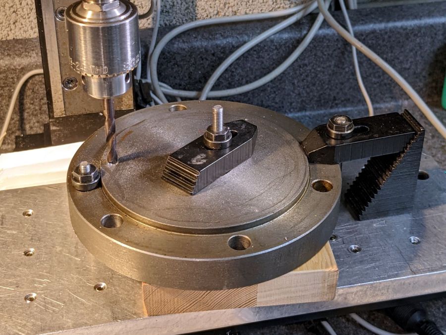
5 inch 4 jaw chuck – adapter plate drilling
Of course, the Sherline lacks enough throat for the plate, so each hole required clamping / locating / center-drilling / drilling / finish drilling. With all three drilled, hand-tapping the threads was no big deal:
5 inch 4 jaw chuck – rebuIlt adapter plate
Those are M8×1.25 studs from LMS (although the ones I got look like the 30 mm version), with the long end sunk in the adapter plate to put the other end flush with the nut on the far side of the spindle plate:
5 inch 4 jaw chuck – installed – spindle nuts
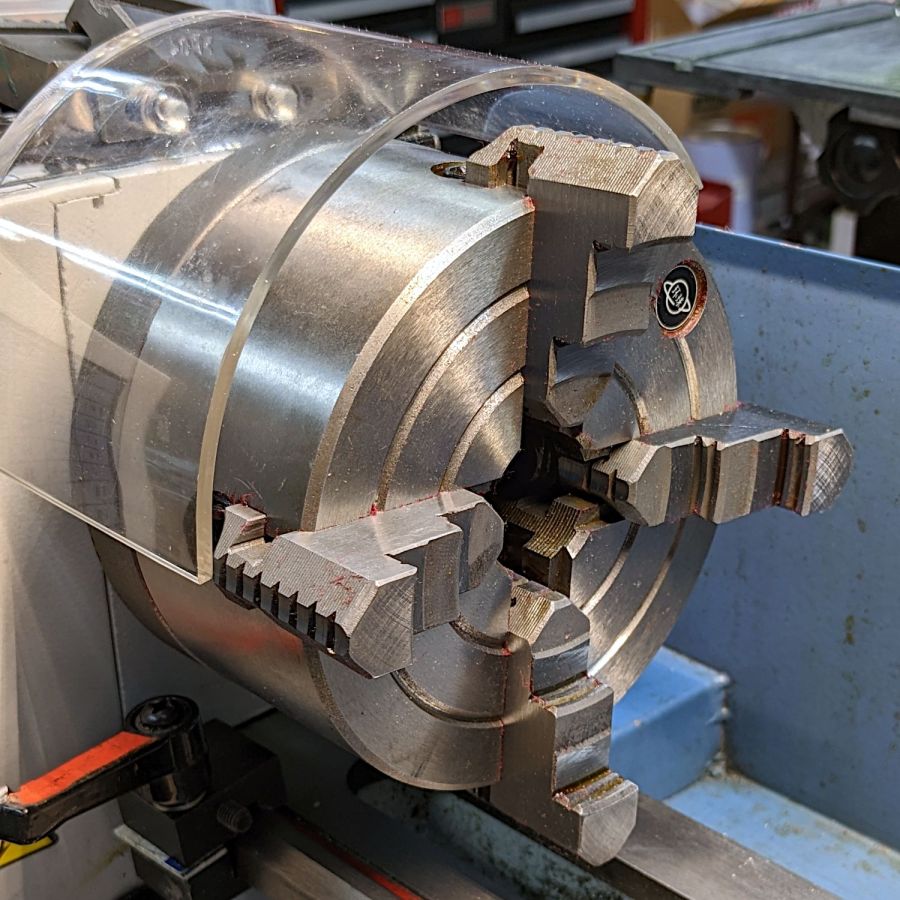
And then it fits just like it grew there, although the jaws don’t have much clearance inside the interlock cover:
5 inch 4 jaw chuck – installed – front view
Now I’m ready for the next set of coasters and, if the jaws stick out too far, I can gimmick the interlock switch for the occasion.
The description of the 4 inch chuck seems inconsistent with its listed dimensions, which may be why I ended up with the larger chuck in the first place. You can never have enough chucks: all’s well that ends well.
Lacking a 4-jaw chuck for the lathe, this should suffice:
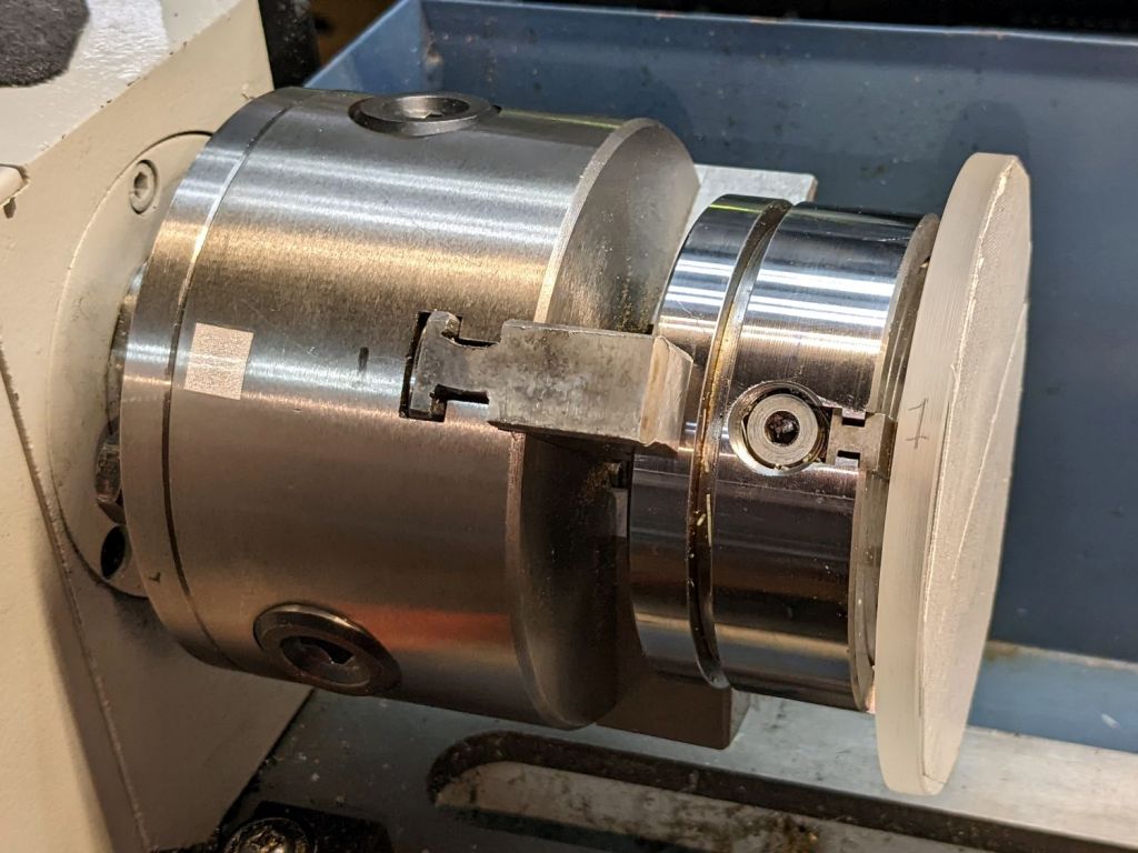
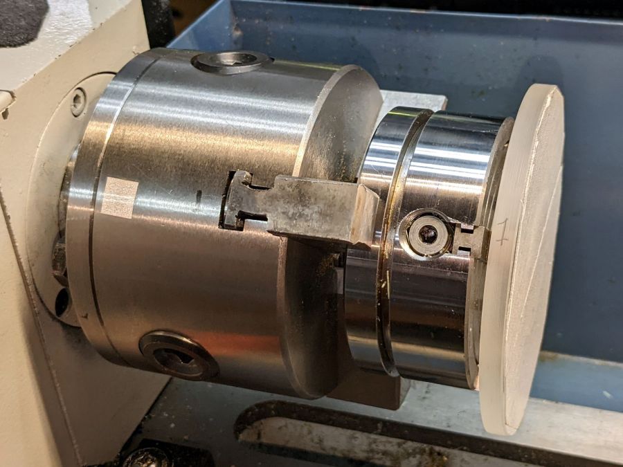
Coaster Epoxy Rim – chuck-in-chuck setup
Which is just the Sherline 4-jaw chuck chucked in the lathe’s 3-jaw chuck, with both chuck Jaw 1 positions lined up and marked on the acrylic disk fixture. The picture is a recreation set up after the fact, because I lack a good picture of the overall scene.
Now it’s easy enough to center the fixture, stick the coaster in place with reasonable accuracy, then tweak the Sherline chuck to center the coaster:
Coaster Epoxy Rim – turning setup
Because the bottom layer is a laser-cut disk, eyeballometrically aligning its edge to a simple pointer worked surprisingly well:
Coaster Epoxy Rim – locating mirror edge
Turning the OD down to match the bottom disk meant I could finally get decent results with zero drama:
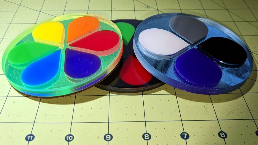
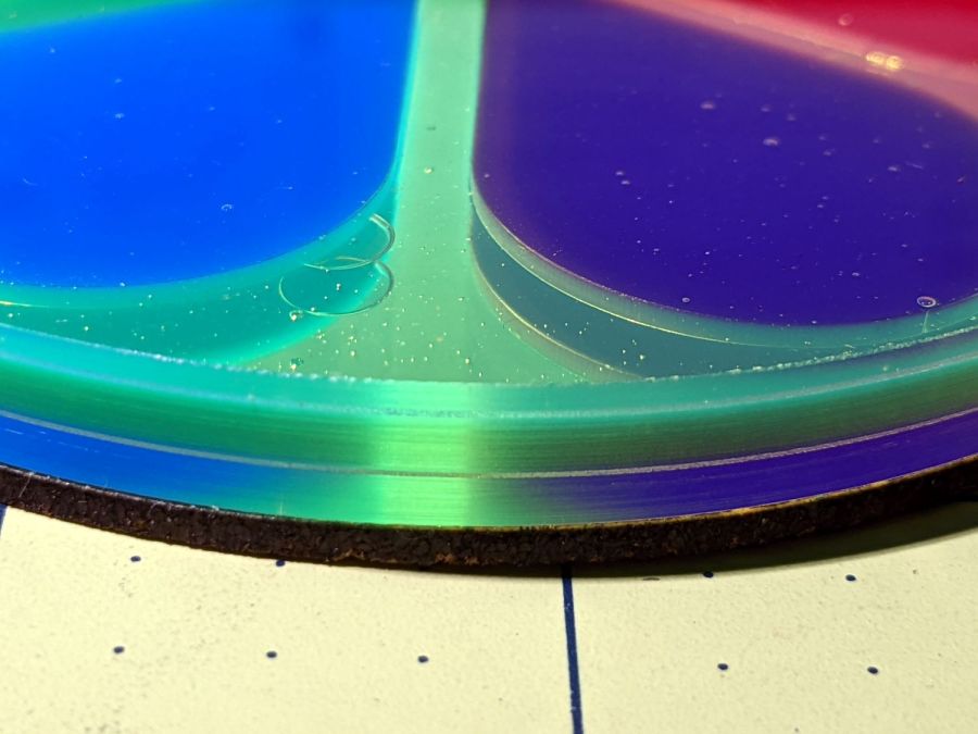
Coaster Epoxy Rim – turned samples
From the bottom, this one has a 3 mm mirror, the 3 mm fluorescent green frame + petals, and a 1.6 mm top sheet:
If I never tell anybody, they’ll think the slightly granular look of the tape was deliberate; it looks OK to me.
And, for completeness, the crash test dummy from the start of this adventure:
Coaster Epoxy Rim – turned 6 petal black
I don’t know how to avoid the bubbles, as the usual torch-the-top and pull-a-vacuum techniques pop bubbles at the epoxy-air interface. These bubbles are trapped under the top acrylic sheet, even though I was rather painstaking about easing the layer down from one side to the other while chasing bubbles along.
Maybe I can define bubbles as Part of the Art?
Definitely fancier than chipboard, although not nearly as absorbent.
The ID is bigger and the OD is smaller than the fixture, so it won’t get in the way of further proceedings:
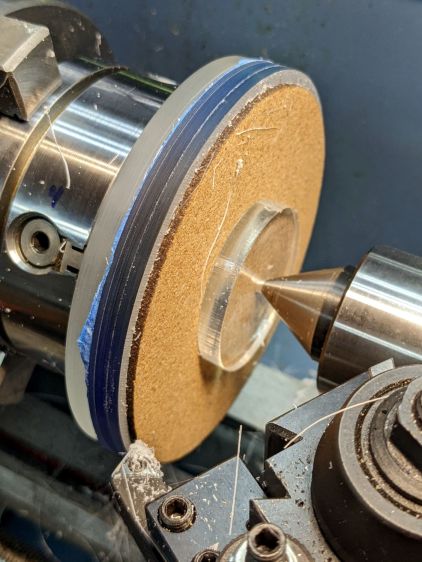
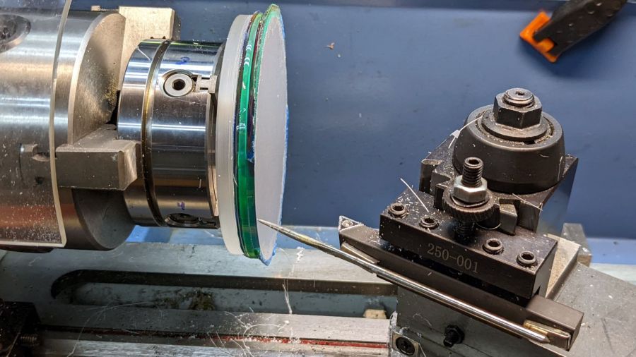
Coaster Epoxy Rim – 3-jaw lathe setup
The pad on the live center came from the cookie cut from the fixture, with a just slightly off-center 3 mm hole poked into it to hold the point away from the coaster.
A ring of carpet tape on the fixture provides traction holding the coaster in place:
Coaster Epoxy Rim – carpet tape
That turned out to be more trouble than it was worth; scissoring a pair of strips to fit the OD works just fine.
In any event, the live center applies enough pressure to keep the adhesive happy.
The fixture disk is sacrificial, so it now has a notch around its front face where the cutter cleared the coaster.
Although I intended to shim the fixture against the chuck jaws to center the coaster, my first attempt at manually centering the thing on the fixture was Close Enough™ that I just turned the OD to see how well the whole process worked:
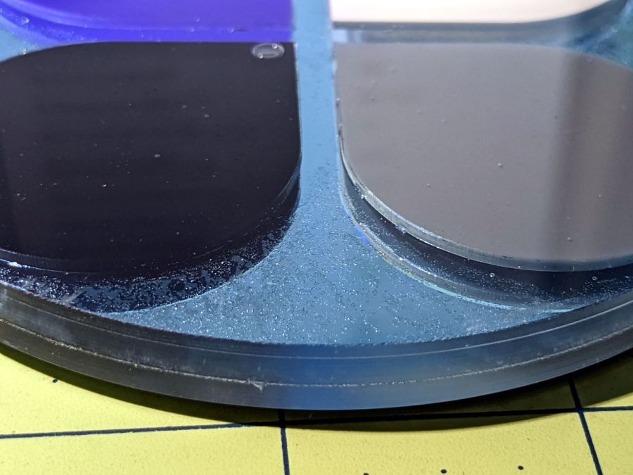
Coaster Epoxy Rim – turned 6 petal black
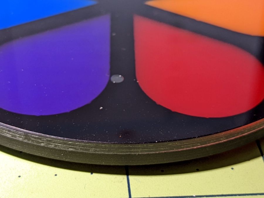
The edge finish is arguably not Good Enough™, but it looks much better in person. In particular, the difference between the transparent acrylic top layer and the black acrylic frame around the petals is much more prominent in the photo, perhaps due to scatter from the overhead desk light.
This was the original crash test dummy acrylic coaster, so more care will be in order for the next set. In particular, shimming the fixture requires removing and replacing it for each adjustment, which can easily become a non-converging process.
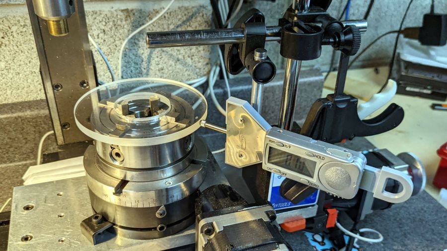
Because the Sherline mill can’t cut all the way around a 4 inch OD coaster clamped to its table, I set up the 4-jaw chuck on the rotary table and centered the nicely round fixture:
Coaster Epoxy Rim – centering fixture plate
Admittedly, the centering need not be so precise, but practice makes perfect.
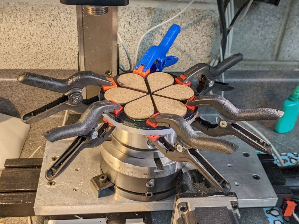
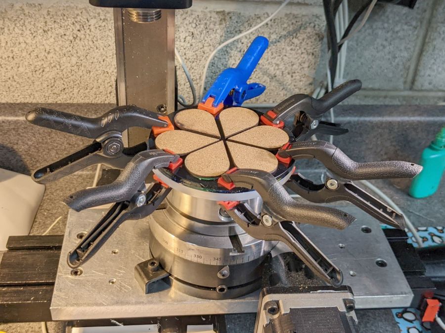
A few sissy cuts demonstrated the tape lacked sufficient stickiness to hold the coaster in place against the milling cutter’s uplift. I managed to mill most of the perimeter with those clamps in place, moving each one from just ahead of the cutter to just behind the cutter.
That way lies both madness and organic damage.
There are better tapes and better adhesives, all trading off a really sticky fixture against difficulty extracting an undamaged part.
A more complex circular fixture with built-in mechanical edge clamps extending around a major part of the perimeter seems like entirely too much of a diversion for a couple of obscene-gerund coasters.