A lithium battery management system can (and should!) disable the battery output to prevent damage from overcurrent or undervoltage, after which it must be reset. The inadvertent charge port short may have damaged the BMS PCB, but did not shut down the battery’s motor output, which means the BMS will not should not require resetting. However, because all this will happen remotely, it pays to be prepared.
A description of how to reset the BMS in a similar battery involves poking bare hot wires into the battery terminals, which IMO is akin to Tickling The Dragon’s Tail. The alert reader will note that the “Shark” battery shown on that page has its terminal polarity exactly opposite of the “Ultra Slim Shark” battery on our bikes. Given the energies involved, eliminating any possible errors makes plenty of sense.
The battery connector looks like this:

For this battery, the positive terminal is on the right, as shown by the molded legend and verified by measurement.
A doodle with various dimensions, most of which are pretty close:

Further doodling produced a BMS reset adapter keyed to fit the battery connector in only one way:

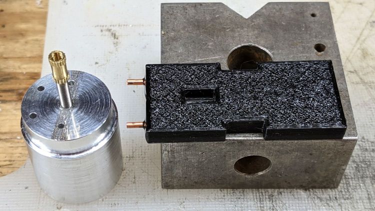
Which turned into the rectangular lump at the top of the tool kit, along with the various shell drills and suchlike discussed earlier:

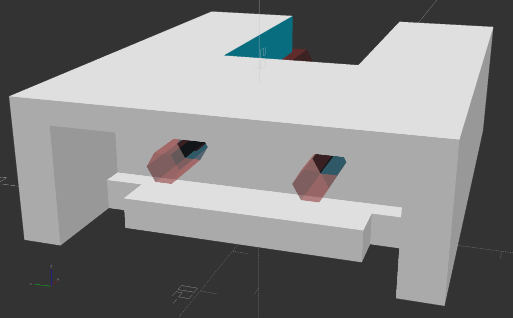
Looking into the solid model from the battery connector shows the notches and projections that prevent it from making incorrect contact:

The pin dimensions on the right, along with a mysterious doodle that must have meant something at the time :

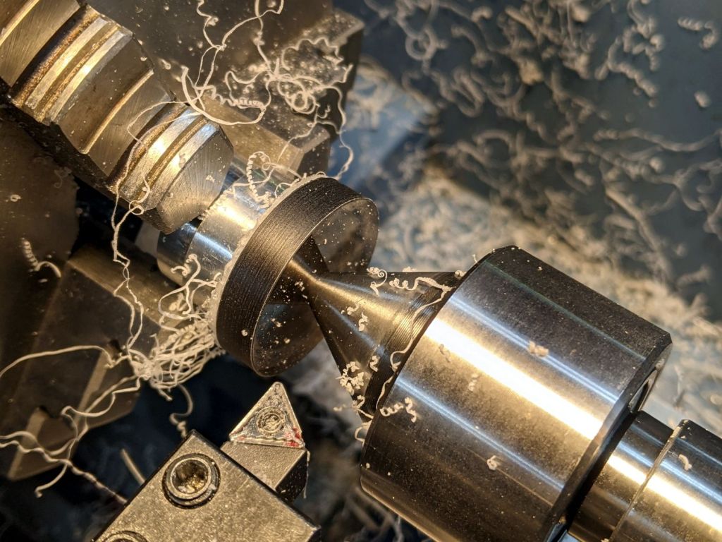
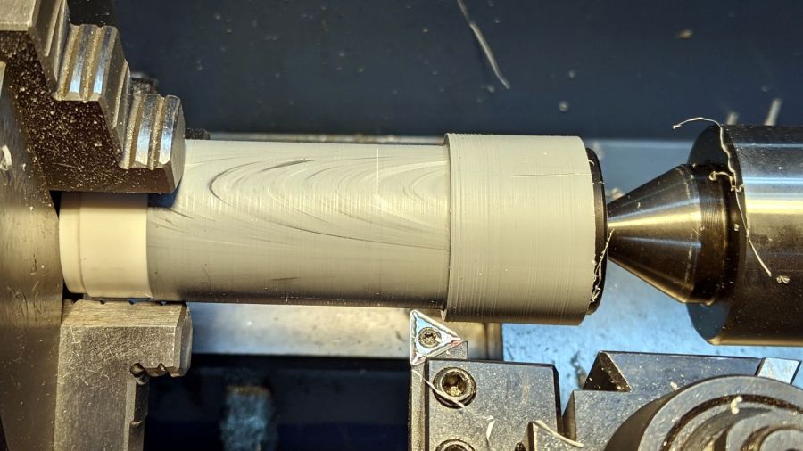
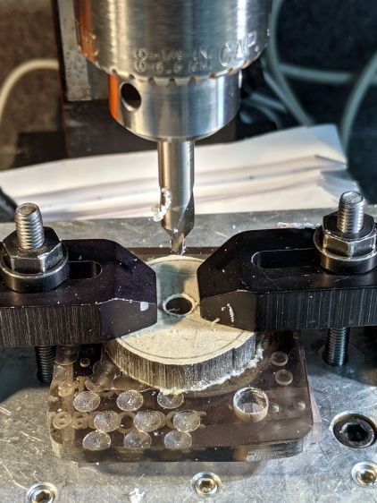
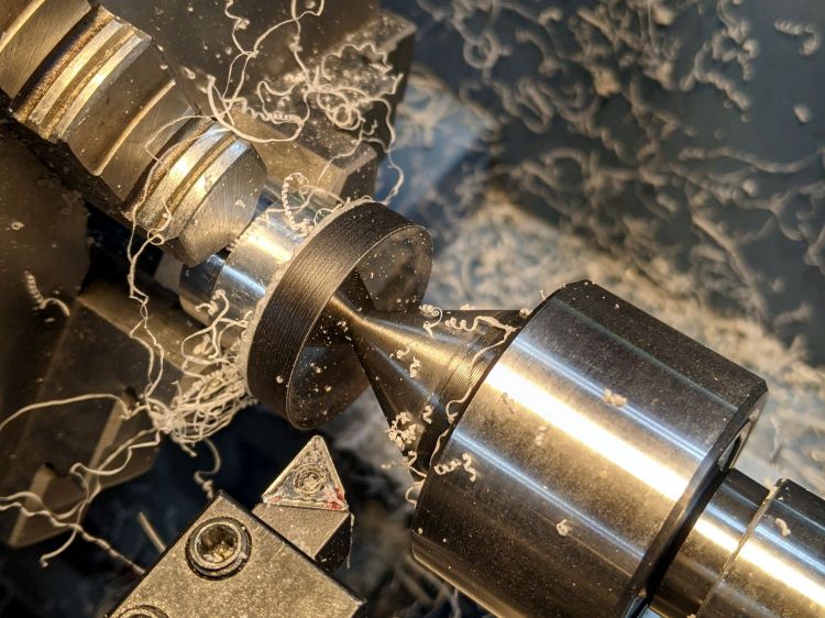
The pins emerged from 3/16 inch brass rod, with pockets for the soldered wires:

The wires go into a coaxial breakout connector that’s hot-melt glued into the recess. The coaxial connectors are rated for 12 V and intended for CCTV cameras, LED strings, and suchlike, but I think they’re good for momentary use at 48 V with minimal current.
I printed the block with the battery connector end on top for the best dimensional accuracy and the other end of the pin holes held in place by a single layer of filament bridging the rectangular opening:

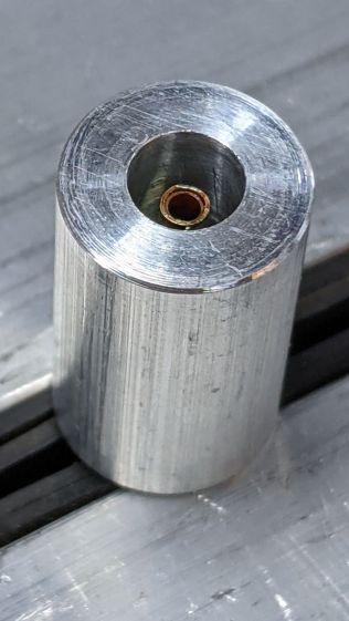
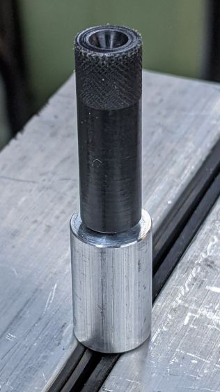
I made a hollow punch to cut the bridge filaments:

The holes extend along the rectangular cutout for the coaxial connector, so pressing the punch against the notch lines it up neatly with the hole:

Whereupon a sharp rap with a hammer clears the hole:

A dollop of urethane adhesive followed the pins into their holes to lock them in place. I plugged the block and pins into the battery to align the pins as the adhesive cured, with the wire ends carefully taped apart.
After curing: unplug the adapter, screw wires into coaxial connector, slobber hot melt glue into the recess, squish into place, align, dribble more glue into all the gaps and over the screw terminals, then declare victory.
It may never be needed, but that’s fine with me.
[Update: A few more doodles with better dimensions and fewer malfeatures appeared from the back of the bench.]


The OpenSCAD source code as a GitHub Gist:
| // Adapter to reset Bafang battery management system | |
| // Ed Nisley KE4ZNU Dec 2021 | |
| Layout = "Block"; // [Show, Build, Pins, Block, CoaxAdapter, Key] | |
| Gap = 4.0; | |
| /* [Hidden] */ | |
| ThreadThick = 0.25; | |
| ThreadWidth = 0.40; | |
| HoleWindage = 0.2; | |
| Protrusion = 0.1; // make holes end cleanly | |
| inch = 25.4; | |
| function IntegerMultiple(Size,Unit) = Unit * ceil(Size / Unit); | |
| module PolyCyl(Dia,Height,ForceSides=0) { // based on nophead's polyholes | |
| Sides = (ForceSides != 0) ? ForceSides : (ceil(Dia) + 2); | |
| FixDia = Dia / cos(180/Sides); | |
| cylinder(d=(FixDia + HoleWindage),h=Height,$fn=Sides); | |
| } | |
| ID = 0; | |
| OD = 1; | |
| LENGTH = 2; | |
| //———————- | |
| // Dimensions | |
| WallThick = 3.0; | |
| PinSize = [3.5,4.75,9.0 + WallThick]; // LENGTH = exposed + wall | |
| PinFerrule = [3.5,4.75,10.0]; // larger section for soldering | |
| PinOC = 18.0; | |
| PinOffset = [-9.0,0,9.0]; | |
| Keybase = 4.0; // key bottom plate thickness | |
| KeyBlockSize = [15.0,50.0,15.0]; | |
| CoaxSize = [35.0,15.0,11.0]; | |
| CoaxGlue = [0,2*2,1]; | |
| // without key X section | |
| BlockSize = [CoaxSize.x + WallThick + PinFerrule[LENGTH],KeyBlockSize.y,KeyBlockSize.z + WallThick]; | |
| echo(BlockSize=BlockSize); | |
| //———————- | |
| // Battery connection pin | |
| // Used to carve out space for real brass pin | |
| // Long enough to slide ferrule through block | |
| module Pins() { | |
| for (j=[-1,1]) | |
| translate(PinOffset + [0,j*PinOC/2,0]) | |
| rotate([0,90,0]) | |
| rotate(180/6) { | |
| PolyCyl(PinSize[ID],BlockSize.x,6); | |
| translate([0,0,PinSize[LENGTH]]) | |
| PolyCyl(PinSize[OD],BlockSize.x,6); | |
| } | |
| } | |
| //———————- | |
| // Coaxial socket adapter nest | |
| // X=0 at left end of block, Z=0 at bottom | |
| // includes glue, extends rightward to ensure clearance | |
| module CoaxAdapter() { | |
| translate([0,0,CoaxSize.z]) | |
| cube(CoaxSize + CoaxGlue + [CoaxSize.x,0,CoaxSize.z],center=true); | |
| } | |
| //———————- | |
| // Block without key | |
| // X=0 at connector face, Z=0 at bottom of block | |
| module BareBlock() { | |
| difference() { | |
| translate([BlockSize.x/2,0,BlockSize.z/2]) | |
| cube(BlockSize,center=true); | |
| Pins(); | |
| translate([BlockSize.x,0,Keybase]) | |
| CoaxAdapter(); | |
| } | |
| translate([BlockSize.x – CoaxSize.x,0,BlockSize.z/2]) // bridging layer | |
| cube([ThreadThick,BlockSize.y,BlockSize.z],center=true); | |
| } | |
| //———————- | |
| // Complete block | |
| module Block() { | |
| BareBlock(); | |
| BatteryKey(); | |
| } | |
| //———————- | |
| // Battery connector key shape | |
| // Chock full of magic sizes | |
| // Polygons start at upper left corner | |
| module BatteryKey() { | |
| // base outline | |
| kb = [[-15,KeyBlockSize.y/2],[0,KeyBlockSize.y/2],[0,-KeyBlockSize.y/2],[-15,-KeyBlockSize.y/2]]; | |
| // flange cutout | |
| kf = [[kb[0].x,20],[-3,20],[-3,15],[-8,15],[-8,-15],[-3,-15],[-3,-20],[kb[0].x,-20]]; | |
| // sidewalls | |
| kw = [[-15,KeyBlockSize.y/2],[0,KeyBlockSize.y/2],[0,20],kf[0]]; | |
| linear_extrude(height=Keybase) | |
| difference() { | |
| polygon(kb); | |
| polygon(kf); | |
| } | |
| linear_extrude(height=KeyBlockSize.z) | |
| polygon(kw); | |
| mirror([0,1,0]) | |
| linear_extrude(height=KeyBlockSize.z) | |
| polygon(kw); | |
| translate([0,0,KeyBlockSize.z]) | |
| linear_extrude(height=BlockSize.z – KeyBlockSize.z) | |
| polygon(kb); | |
| } | |
| //———————- | |
| // Build it | |
| if (Layout == "Block") { | |
| BareBlock(); | |
| } | |
| if (Layout == "Pins") { | |
| Pins(); | |
| } | |
| if (Layout == "Key") { | |
| BatteryKey(); | |
| } | |
| if (Layout == "CoaxAdapter") { | |
| CoaxAdapter(); | |
| } | |
| if (Layout == "Show") { | |
| Block(); | |
| color("Brown",0.3) | |
| Pins(); | |
| } | |
| if (Layout == "Build") { | |
| rotate([0,90,0]) | |
| translate([-BlockSize.x,0,0]) | |
| Block(); | |
| } | |