The Smell of Molten Projects in the Morning

Ed Nisley's Blog: Shop notes, electronics, firmware, machinery, 3D printing, laser cuttery, and curiosities. Contents: 100% human thinking, 0% AI slop.

Tag: M2

Using and tweaking a Makergear M2 3D printer

  • Makergear M2: Z Axis Numbers

    Now that I understand why the M2 Z axis stepper gets so hot, the question is: does it matter?

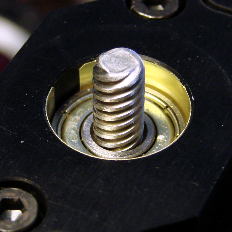
    The Z axis stage moves very smoothly along the two guide rails, so there’s little friction and no binding involved. I can’t weigh the thing without dismantling the whole printer, which isn’t going to happen right now, but some crude experiments indicate that 7 pounds = 3 kgf = 30 N isn’t too far from the truth.

    The 8 mm OD leadscrew has a 4-start thread at 3.25 turn/inch = 0.311 inch/turn = 0.13 turn/mm = 7.8 mm/turn.

    [Update: Thanks to Jetguy for pointing out the blindingly obvious fact that it’s really 8 mm/turn = 0.125 turn/mm and you can do the inch conversion yourself if you need it. That doesn’t materially affect the results, given that they have about one significant figure of accuracy to start with.]

    The firmware uses 1/16 microstepping at 400 step/mm = 3077 3200 step/turn.

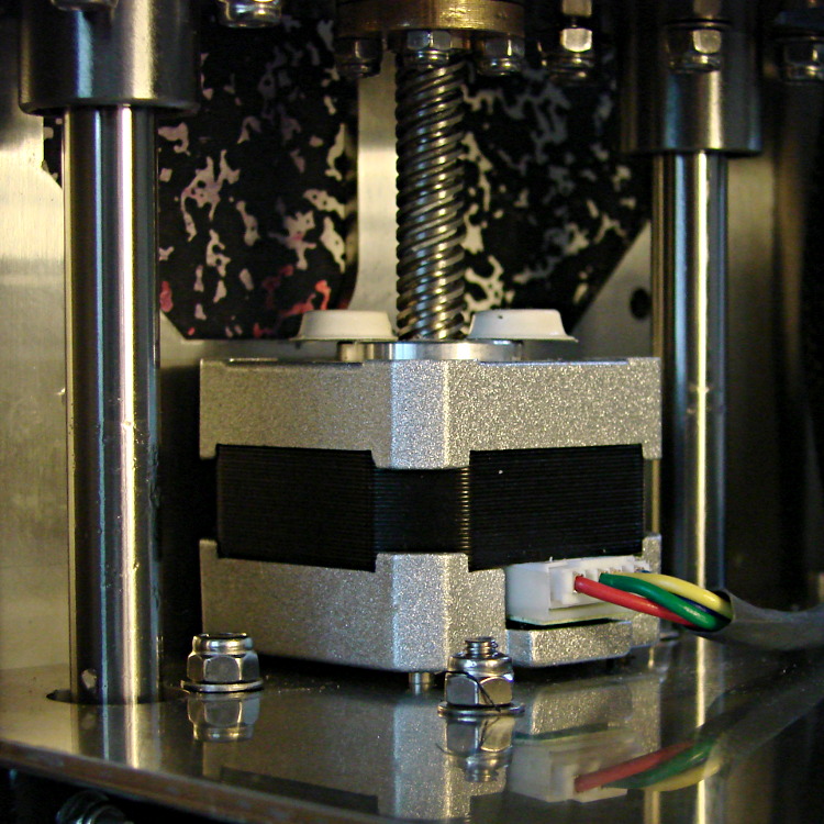
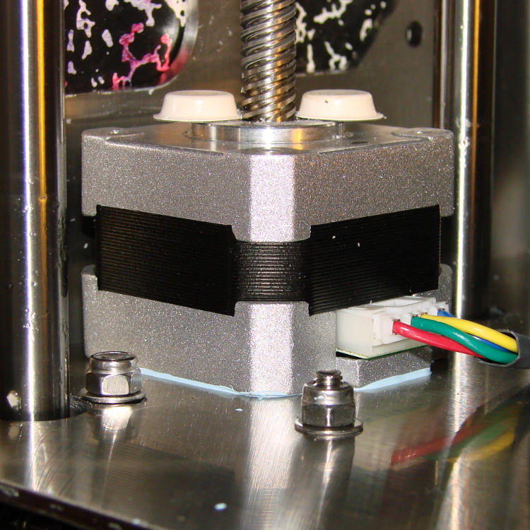
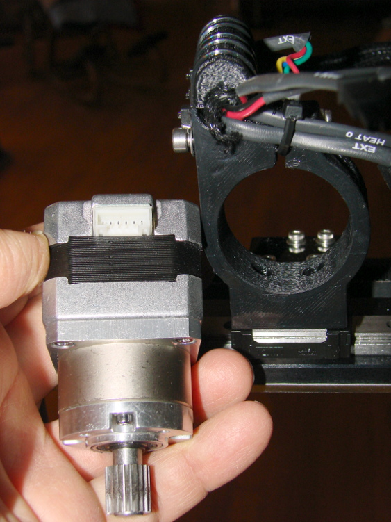
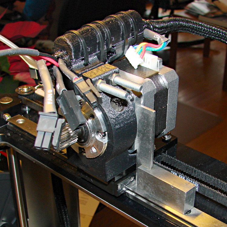
    Using a pull scale to, yes, pull a string wound around the knob on the Z axis leadscrew shows about 1 pound raises the platform at a slow, constant speed. The polygonal knob is about 35 mm in diameter, so the torque works out to 11 ounce·inch = 80 mN·m. Presumably, holding the platform at a given position would require somewhat less torque, but I can’t measure that with any confidence.

    The motor has very little excess torque: a gentle touch can stall the Z axis motor as it raises the stage. I guesstimate the motor produces 150 mN·m, tops, during low-speed motion at 600 mA.

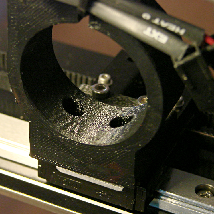
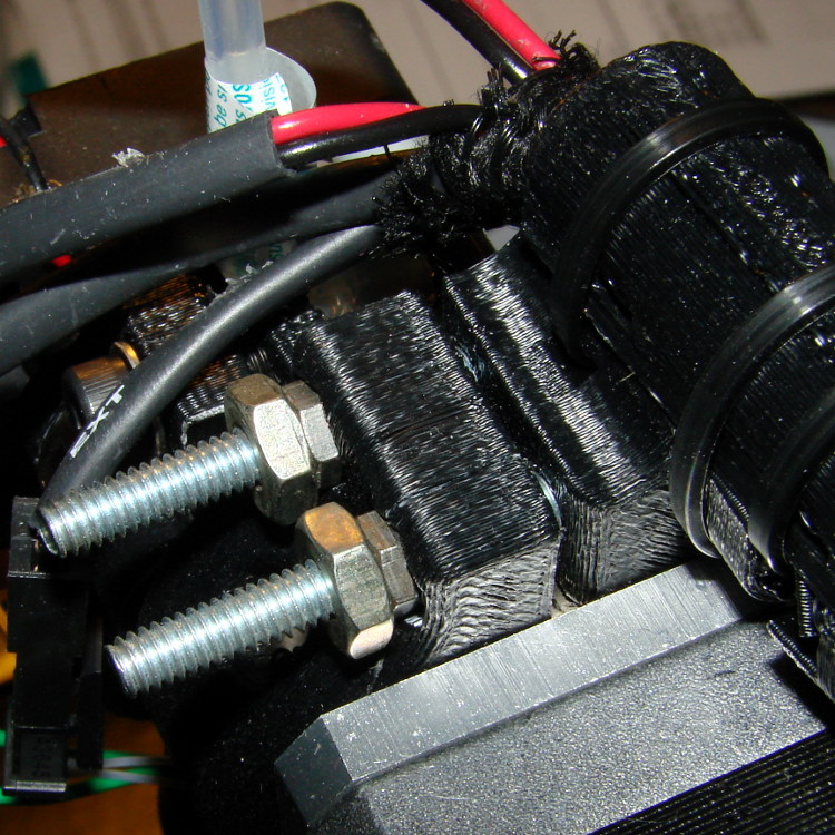
    Lowering the stage requires no effort at all: it falls under its own weight, prompting me to install those bumpers. The design doesn’t have much compliance, but it’s well-adjusted and works fine.

    Searching with the appropriate keywords produces a 17HD-B8X300-H motor from Kysan:

    • 12 V
    • 400 mA
    • 30 Ω
    • 42 mH
    • 2.6 kg·cm = 260 mN·m

    That’s a close-enough match to suggest my measurements are in the right ballpark. The extremely high resistance and inductance indicate this is the wrong motor for a high-performance microstepping application.

    The firmware has DEFAULT_MAX_ACCELERATION = 30 mm/s2 for the Z axis. It’s 9000 for X and Y, 10000 for the extruder. The extremely low Z acceleration says there’s something badly wrong with this setup.

    There is also a DEFAULT_ACCELERATION = 3000 for all axes. I don’t know how that interacts with the per-axis limit, but I’m certain the Z axis doesn’t come close to that value.

    I do not know how the firmware actually handles motor steps while ramping up and down, but I do intend to clamp a current probe around a motor wire and measure what goes on. Let us assume it works in the usual way all ideal components behave in physics labs.

    Assuming a constant 30 mm/s2 acceleration for the first half of a 0.25 mm Z axis move, the time should be:

    0.25 / 2 = (1/2) * 30 * t2
    t = 90 ms

    At the end of that ramp-up, the Z stage will be trundling along at:

    v2 = 2 * 30 * 0.25/2
    v = 2.8 mm/s

    The move requires exactly 50 steps = 0.25/2 mm * 400 step/mm.

    Assuming the same deceleration during the second half of the move, a 0.25 mm layer change requires about twice that long: 180 ms for 100 steps.

    Along the X axis, a 0.25/2 mm move requires 5.3 ms and reaches a peak speed of 47 mm/s. The total move requires 11 ms and 22.22 steps (= 0.25 mm * 88.88 step/mm, obviously rounded to 22).

    I think a difference of more than an order of magnitude matters, although some actual measurements are definitely appropriate.

  • Makergear M2: Z-axis Stepper Motor

    Several users have observed that the stepper motor driving the M2’s Z axis leadscrew gets very hot. I measured about 140 °F = 60 °C on the as-built motor, so I loosened the screws and raised the motor slightly:

    M2 Z axis motor - raised
    M2 Z axis motor – raised

    I eased some heatsink compound underneath by putting dabs on a slip of paper and painting it on the bottom of the motor case, lowered the Z stage to the bottom of its travel, and tightened the mounting screws:

    M2 Z axis motor - added thermal compound
    M2 Z axis motor – added thermal compound

    That reduced the temperature to about 120 °F = 50 °C, which still seemed excessive for a short-stack motor mounted on a fairly large chunk of stainless steel. The motor also sounded quite rough during homing and long manual moves, sooo … something was wrong. I bet you know where this is going, right?

    Let’s start with the firmware side and determine what current the motor should be seeing.

    The M2 uses a slightly modified version of the Marlin firmware running on a RAMBo 1.1b board. The basic RAMBo doc gives these equations relating the peak winding current Imax to the constant W that defines it in the firmware:

    Vref = 0.8 * Imax
    W = 255 * (Vref / 1.66)

    Mashing those together produces this:

    W = 255 * (0.8 * Imax) / 1.66

    The default Z axis stepper current constant W (called Z_CURRENT in the Marlin source) is 135. The board in my M2 has R30 = 3.3 kΩ, which sets the maximum possible current to 2 A. Working the equation backwards, a Z_CURRENT = 135 will produce a peak winding current of 1.1 A.

    However, a nearby comment in the source code suggests this is should be about 0.75 A. The original RAMBo board had a maximum possible current of 1.5 A, but running those numbers doesn’t agree. Another comment suggests 185 corresponds to about 1 A, which isn’t right, either. There’s nothing new about stale comments not corresponding to the actual hardware; I’ve done that myself.

    With 1.1 A in hand, let’s unplug the cable and measure the winding resistance.

    Not much to my surprise, the motor has 28 Ω windings. The M2 uses a 19 V supply for the steppers, so the maximum motor current works out to 19 V/28 Ω  = 680 mA, but it must be less than that to allow the microstepping controller to manage the current.

    It seems that Makergear is connecting a high-resistance stepper intended for a simple H-bridge drive to a high-performance microstepping controller. For some background on why that combination doesn’t work, see my analysis of the original MBI Thing-O-Matic steppers.

    I thought we all agreed we weren’t going to do that any more. Maybe nobody sells a low-resistance motor-with-integral-leadscrew?

    Anyhow.

    The only thing to do in the short term is to reduce the peak current to a rational value around 600 mA:

    74 = 255 * (0.8 * 0.6) / 166

    I set it to a nice, round 75 and reloaded the firmware, which immediately made the motor hum, rather than growl, on long moves. The case temperature didn’t drop by very much, because the poor motor still dissipates about 11 W, not much less than the original 13 W. There’s only so much heat you can pull out of the case and these little motors are actually rated for maybe 5 W, tops.

    The motor’s overall performance didn’t change, which is good, because it didn’t have much performance to begin with. The X and Y motors can accelerate at 9000 mm/s2, but the Z motor limit is 30 mm/s2; it doesn’t really accelerate, it sort of gains momentum in a stately manner.

    Next: let’s see if it really matters.

  • Makergear M2: Filament Drive

    The M2 filament drive works surprisingly well. The OD of the curved section around the drive gear could easily be another few millimeters larger, which would put the mounting screw holes completely within the plastic perimeter:

    M2 extruder - filament embossing
    M2 extruder – filament embossing

    I haven’t changed the position of the filament compression screw and the default setting produces a really aggressive grip on the filament; the picture shows the deep track from the drive gear in the natural-color PLA filament along the bottom of the opening. That may be entirely too much of a good thing, but I’ll leave well enough alone for now.

    Makergear had scraped out the recess that accepts the end of the motor gearbox housing, but it still didn’t quite fit the motor’s snout, so I continued the scraping job until the drive sat square on the end of the gearbox. It mounts to the gearbox with three screws: the gearbox has four threaded holes, but the fourth screw would pass through an inconvenient spot above the bearing / below the compression screw / beside the filament / inside the clamp arm.

    Perhaps rotating the motor slightly would reposition the mounting holes a bit better? Disadvantage: hard to make the extruder sit vertically with a crooked motor. Maybe integrate the extruder with the motor mount, so the vertical reference comes from the X stage linear slide platform and the mount forces the proper motor and extruder alignment?

    The filament compression screw is offset rearward from the filament, so the upper part of the clamp must apply serious torque through its plastic body to the bearing pressing the filament against the drive gear:

    M2 extruder - added filament guide
    M2 extruder – added filament guide

    I think a spring-loaded bearing would work better, with force applied through a pair of springs bracketing the bearing to reduce the single-point load and torque, with a hinge pin below the bearing. The Wade-ScribbleJ bearing clamp on the Thing-O-Matic has worked perfectly since I installed it, but there are now simpler designs out there that should be adaptable.

    The twist of paper embedded in a blob of hot-melt glue encourages the filament guide tube to stand up straight and not flop over during reversals. That should be somewhat longer and fit neatly around the guide; it should be part of the filament drive body. This end of the guide tube should not be anchored, so it can pop upward when the filament reverses; there’s no need to push the filament backwards through a fixed guide tube at full reversal speed.

    The drive came pre-assembled to and aligned with the hot end, here seen without the paper / glue guide after the first-pass assembly:

    M2 extruder wiring
    M2 extruder wiring

    I want to insert strain gauges between the mount and the extruder barrel in order to measure the force applied to the hot end during extrusion, but it’s not clear how to do that with this design. I think I must build a bench model that extrudes a plastic tangle into air before I understand the problems. Again, an integrated motor + extruder mount might work better.

    The PTFE (?) filament guide tube had both ends slightly crimped from the pliers that cut it off the reel, which isn’t unexpected. I reshaped / reamed the ends of the tube to pass the filament without undue friction. There’s still a bit too much friction, methinks, but it doesn’t pose a problem yet.

    The spool holder and filament guide don’t match the drawings at all; some discussions in the Google Group indicate this design works much better than the original, fiercely complex, design.

    The end of the filament guide tube over the spool also tends to flop over and bend the filament, so I blobbed enough hot melt glue around it on the guide bracket to both anchor it and enforce good alignment. The red cable tie holds the blob in place, as there’s no mechanical interlock on the bracket for the glue to grab:

    M2 spool filament guide anchor
    M2 spool filament guide anchor

    Another design for a much longer bracket positions the guide tube over the spool’s midline, which should reduce the snap when the filament slips over a bunching on one side or the other. I think I’ll gimmick up something with an integral alignment doodad for the filament tube.

    The guide tube reorients the filament to be tangential to the spool, with the bracket providing the reaction force required to hold the guide tube in place while the filament transmits force from the extruder motor that unrolls the filament. Given that we know exactly how much filament travels into the extruder, we could add a motor drive to unroll exactly that amount from the spool and maintain the length of the filament loop without a guide tube. At higher feed rates, that would allow the extruder drive to feed filament into the hot end without any drag, thus eliminating any effects not related to the actual extrusion process. I like that sound…

  • Makergear M2: Extruder Motor Mount

    The general idea is that the extruder motor mount will clamp the exceedingly smooth and totally featureless circumference of the motor gearbox:

    M2 extruder - motor and mount
    M2 extruder – motor and mount

    The as-built interior of the circumferential clamp has enough ripples and ridges and imperfections that it can’t get a solid grip on the metal gearbox:

    M2 extruder - motor mount clamp - plastic ripples
    M2 extruder – motor mount clamp – plastic ripples

    That allows the motor to rotate slightly in the mount, with what seemed like very little torque, and misalign the extruder nozzle with respect to the platform. There’s about 80 mm between the motor shaft and the nozzle, so a mere 4° tilt raises the nozzle an additional 0.1 mm, entirely enough to throw off the Z axis height setting.

    I smoothed the worst of the bumps with a file and applied a generous dose of rosin for a better grip. Two Nylock nuts sunk into the motor mount anchor a pair of M4 screws that compress the circumferential clamp around the motor, but there’s not enough plastic around them for proper support and the mount promptly cracked in exactly the places you’d expect. I reamed out the holes to pass overly long 10-32 pan-head screws, scraped out the nut traps to accept 10-32 nuts, then added two small nuts and a large jam nut to each one:

    M2 - Extruder motor clamp - 10-32 screws
    M2 – Extruder motor clamp – 10-32 screws

    That’s a temporary expedient until I rebuild the entire mount, as the plastic remains split and the clamp isn’t applying uniform pressure to the gearbox.

    The extruder motor mount on my M2 doesn’t match the drawings: it seems Makergear changed from a one-piece extruder motor mount (which required slipping the extruder cable loom and connectors through a tunnel above the motor) to a two-piece design (which clamps the cable between two U-shaped strips). Unfortunately, there’s simply not enough plastic to provide sufficient strength in several vital sections; the nuts just described being one.

    More conspicuously, the lower U-shaped cable clamp strip cracked just behind the motor clamp body, because the plastic filaments run across the mount, perpendicular to the direction of maximum stress and have very little cross-sectional area. I applied extra cable ties on both sides of the fracture, so that the top strip serves as splint for the lower:

    M2 - cracked extruder cable guide
    M2 – cracked extruder cable guide

    That photo shows the M4 Nylock nuts splitting the mount prior to the 10-32 screw fix.

    The wire loom evidently corresponds to the previous mount design, as there’s not enough slack in the thermistor and heater cables to mate the connectors. I trimmed off some loom and rerouted the wires appropriately:

    M2 extruder wiring
    M2 extruder wiring

    With all that in hand, a tiny machinist’s square aligned the motor with the X axis slide and set the extruder perpendicular to the platform:

    M2 extruder - vertical alignment
    M2 extruder – vertical alignment

    I’m unhappy with how that worked out, but it’s good enough for now. I think rebuilding the mount in aluminum will work better for what I have in mind; this seems to be one of the places where 3D printed plastic isn’t quite appropriate.

  • Makergear M2: Heated Build Platform Cable

    The power + thermistor cable for the M2 Heated Build Platform attaches to the Z axis stage at the Y axis motor, with the conductors encased in a fairly stiff braided loom. The cable flexes from fully retracted to fully extended as the HBP moves along the Y axis. Here’s a view at about mid-travel:

    M2 HBP cables - wire loom
    M2 HBP cables – wire loom

    Unfortunately, there’s no provision for strain relief at the HBP or around the connectors. The silicone heating pad firmly anchors the two pairs of power wires to the aluminum plate, but that simply means they flex sharply at the edge of the pad:

    M2 HBP connections
    M2 HBP connections

    I removed the loom between the motor mount and the connectors, but that still doesn’t provide nearly enough flexibility:

    M2 HBP cables - loom removed
    M2 HBP cables – loom removed

    The wires still flex sharply at the outboard side of the connector and at the HBP pad; this can’t possibly survive more than a few thousand long cycles before something expensive breaks. The Thing-O-Matic HBP connector debacle suggests that I may need to attach a strut to the Y axis stage that rigidly supports the connectors, with a much longer loop of wire soaking up the strain to the fixed end.

    The 18 AWG wires carrying the 10+ A of HBP current get unpleasantly warm, suggesting that new loop will require heavier wire. In round numbers from that table, 18 AWG stranded wire runs 6.5 mΩ/ft, so the (roughly) four feet of wire pair between the electronics case and the HBP will drop 250+ mV and dissipate 2.5 W. I suspect it’s worse than that, but haven’t made any measurements to back up that suspicion.

  • Makergear M2: Z Axis Bumpers and Upper Bearing Bushing

    The M2’s Z axis will descend under its own weight with the stepper motor disabled, landing with an emphatic thud when the Nylock nuts holding the leadscrew nut in place hit the top of the motor case. I stuck a pair of rubber feet atop the motor to cushion the impact:

    M2 Z axis motor - added thermal compound
    M2 Z axis motor – added thermal compound

    Yes, that’s thermal compound peeking out from between the motor and the chassis. More about that later, but it derives from those measurements.

    The top end of the leadscrew passes through a ball bearing, but the bearing OD is about 15 mils smaller than the top plate recess ID. I slid a strip of 6 mil brass shimstock around the bearing to soak up the difference and reduce a nasty mechanical resonance:

    M2 Z axis bearing - shimstock bushing
    M2 Z axis bearing – shimstock bushing

    The leadscrew is also a loose fit in the bearing ID, which I’ll correct with a dab of low-strength threadlock when the time comes.

    Note, however, that there’s no other mechanical compliance in the Z axis assembly, so a slightly misaligned leadscrew may actually need that slop when the stage approaches the top of its travel. That wasn’t the case in my printer, but don’t take it for granted; if the leadscrew doesn’t turn easily by hand, remove the shimstock.

  • Makergear M2: Out of Box Experience

    It didn’t take long to realize that Makergear doesn’t actually have any assembly instructions that convert an array of parts bags into a working M2 printer. The box contained a set of subassembly drawings, their internal BOM checklist, and an orange sheet with cautionary notes. So I figured I’d build enough subassemblies to reduce the clutter, then put them together into the chassis while working on Phil’s card table.

    Unfortunately, the BOM on each drawing may not match the drawing, the drawings don’t quite match what’s currently shipped, neither of those match the instructions on the website, the assembly videos / animations aren’t particularly useful (at least to me; I don’t need animated trajectories for nuts and bolts after the first one), not all hardware has a corresponding drawing, and nowhere will you find enough information to actually put the thing together on the first try. Makergear is obviously running as fast as they can, making improvements as they go, and, while the task isn’t impossible, if you’re not pretty good at mechanical assembly, building an M2 from scratch won’t be a pleasant experience.

    A thread on the Makergear Google Group suggests there’s an unofficial “Heathkit style” manual in the offing, which will be a major improvement over the status quo. The catch will be updating the instructions in pace with production improvements, while not losing previous owners along the way. The Google Group has pointers to some good build logs; I regret I can’t contribute anything of the same scale.

    Some assembly notes that don’t fit anywhere else…

    The chassis arrived with the Y axis slide, Z axis stage, and Z axis stepper motor preassembled and aligned in the chassis. Given that’s the part of the process requiring, by their own admission and video example, some finesse, I think they found it impossible for newbies lacking experience.

    CAUTION! If you must assemble the Z axis or modify it, you must remove all four screws from the stepper motor’s case to get it in or out of the chassis. Do not let the motor endcaps fall off or become misaligned, because that will demagnetize the rotor and drastically reduce the available torque. Perhaps wrapping some tape around the sides of the motor to secure the endcaps will prevent disaster. As I’ll describe later, the Z axis motor has barely enough torque for its job and any loss will render it useless.

    Use the shortest possible screws in the two huge rubber feet on the X+ side of the chassis, because the electronics case must fit flush to the chassis just above them. The recommended screws protrude too far through the chassis plate, which is perfectly fine on the X- side.

    Secure the electronics case to the chassis side using M3 screws, instead of the M4 screws that fit the threaded holes, with three M3 washers between the case and the chassis. Put Nylock nuts on the outside of the chassis. You’ll understand why when you get there.

    Tape the picture of the power supply plugs behind the electronics case where you won’t mislay it, because inadvertently swapping the power connectors will not go well.

    Believe it or not, that giant lump of wire on the end of the harness actually fits inside the electronics case. Take it slow and it’ll be all good.

    M2 Electronics Case on chassis
    M2 Electronics Case on chassis

    Cut a cardboard cover (I harvested a shoe box) to fit the build platform and clip it in place whenever you’re not actually building something. You will drop tools on that lovely glass platform…

    Makergear M2 3D Printer with cardboard protecting glass platform
    Makergear M2 3D Printer with cardboard protecting glass platform