Ed Nisley's Blog: Shop notes, electronics, firmware, machinery, 3D printing, laser cuttery, and curiosities. Contents: 100% human thinking, 0% AI slop.
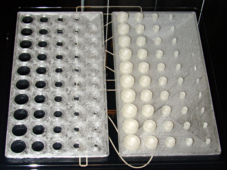
Despite the profusion of surface-finish and print quality test objects, I really care about the dimensions of a 3D printed object, because I tend to build widgets rather than art objects. These two objects, from walter’s Hole and Column Test Print, produce calibrated holes and columns from 0.20 mm to 10.00 mm in diameter, incrementing by 0.20 mm, that should slip neatly together:
M2 – walter hole-column test
Of course, they didn’t, but they came surprisingly close for a first attempt.
The 0.20 and 0.40 posts simply aren’t there, because they’re too small to print with a 0.35 mm diameter nozzle. The 0.60 through 1.40 mm posts were present, albeit fugly, and posts larger than that looked increasingly better.
Although all the holes were present, in the sense that you could see a disturbance in the top and bottom infill pattern, the first visibly open hole appeared at the 0.80 mm spot… and it was immeasurably small. Some holes had misplaced perimeter strands stretching across the openings, which is probably due to excessive speed from my fiddling around with the numbers.
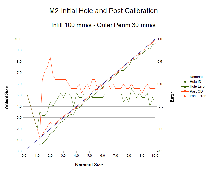
Measuring them with a digital caliper, with no effort at finding the best orientation, then slapping the data into a Libreoffice spreadsheet, produces an interesting graph:
M2 – Initial Hole and Post Diameter Calibration
Above about 3 mm diameter: posts are 0.1 mm too small and holes are 0.3 mm too small. Around 2 mm, posts are too big and holes are way too small. What’s important: above maybe 2.5 mm, the error is essentially constant and does not scale with diameter, so a simple Finagle Constant (or two) can solve (most of) the problem.
Some experiments involving slic3r’s small-perimeter speed seem in order; it was 25 mm/s for these pieces.
More care in measurement would produce better answers, but the real question is whether you can produce holes and columns with known sizes; the answer (as expected) remains “with some care”. That’s not surprising; I expect to have an M2 + PLA version of the small hole diameter Finagle Constant that I’ve been using with Skeinforge + Thing-O-Matic; the correction will certainly fall in the same ballpark.
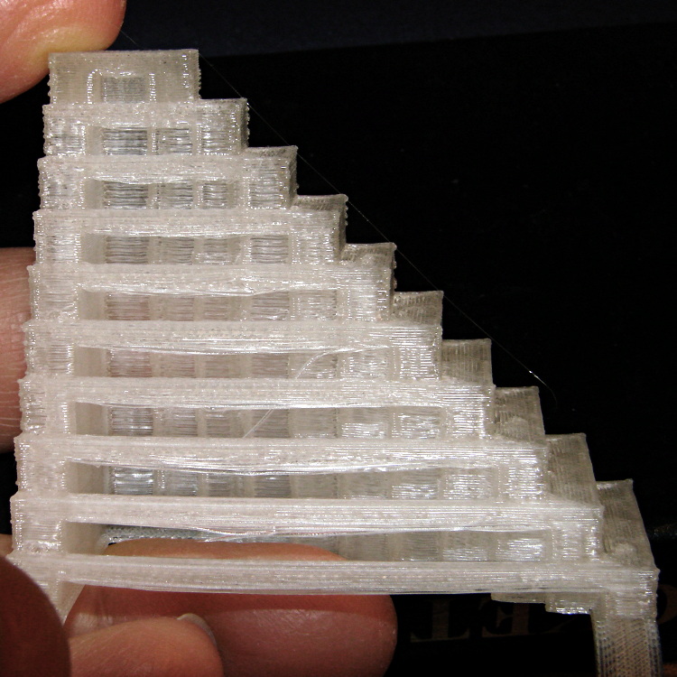
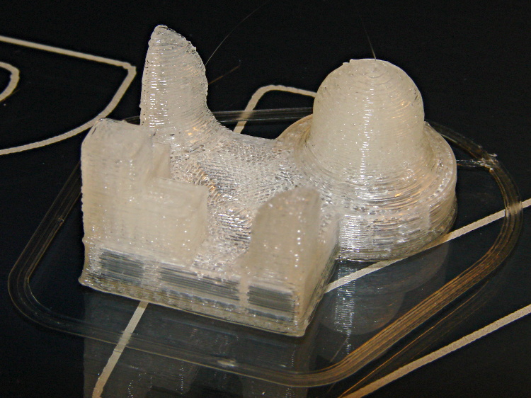
This object from whpthomas’s collection exercises the deprime operation in Sailfish, but it seemed like it’d be useful to verify the Marlin settings in the M2:
M2 – whpthomas deprime test
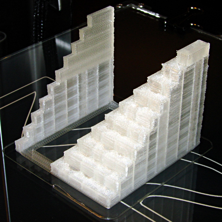
From the other side:
M2 – whpthomas deprime test – view 2
Yes, that was rather anticlimactic. No ooze, no stringing, no surface finish blemishes, just the finished object on the build platform’s glass sheet.
I like that!
The slight bumps on the sharp corner edges seem to be due to the crazy-high perimeter and infill speeds I’ve been playing with, although (I think) those are also where layer changes occurred. The first layer height came out a bit short, so there’s a small flange around the object’s bottom edge; I was figuring out how to get a precise level across the entire surface and stabilize the Z-min switch operation.
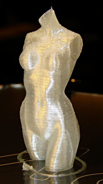
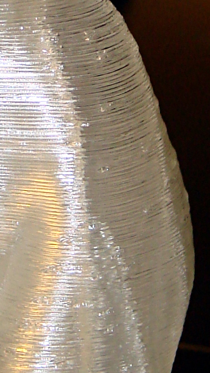
The M2 and slic3r produced this, with the conspicuous vertical bars coming from the 0.10 infill:
M2 – Pink Panther Woman – front
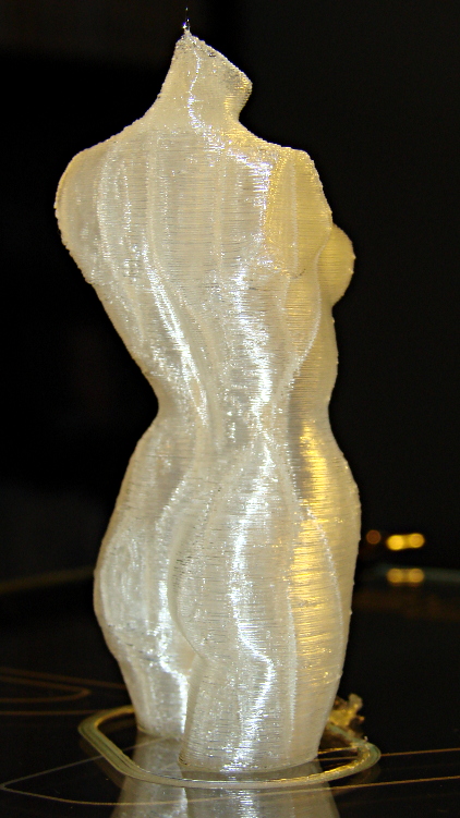
From the rear:
M2 – Pink Panther Woman – rear
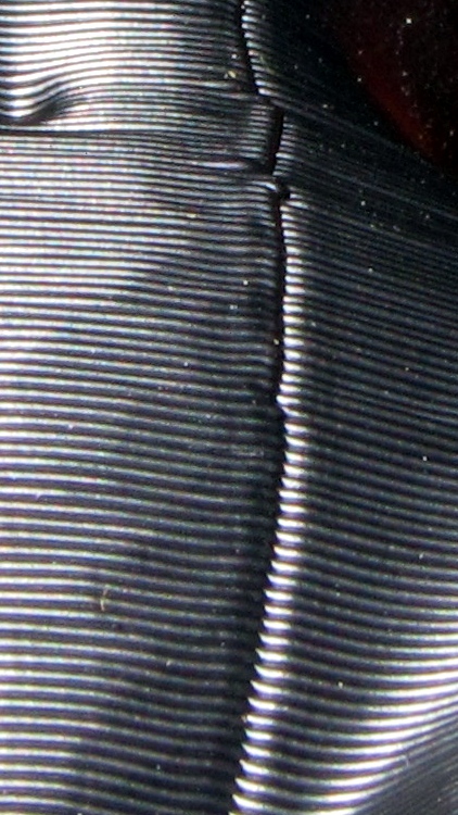
A detail of the left hip shows that slic3r distributes the reversal zits, rather than lining them up in neat columns, and the M2 does a much better job of not depositing blobs at reversals:
M2 – Pink Panther Woman – hip detail
I picked 1.0 mm retraction at either 100 or 300 mm/s, pretty much out of thin air, but even some fine tuning can’t improve that very much. The zits are recessed, so the retraction may be slightly too enthusiastic.
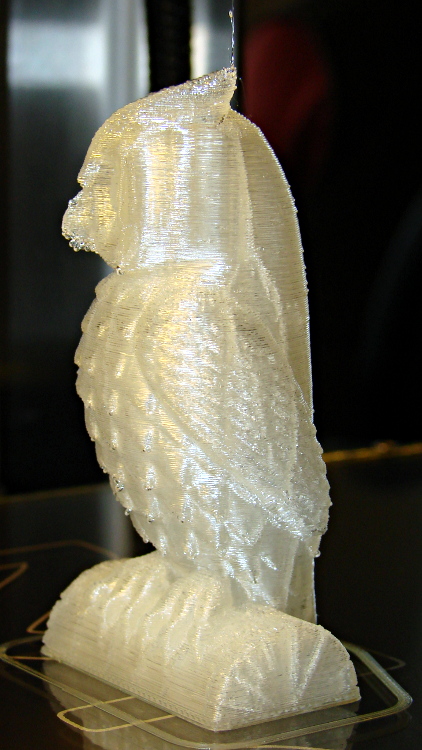
You’ve seen the overview pictures of the half-scale cushwa Owlearlier, so here are some details…
The front view:
M2 – cushwa Owl – half scale
The left side view:
Owl – half size – left
The conspicuous vertical lines come from the 0.10 infill honeycomb; there are no visible retraction zippers and the surface is smooth to the touch.
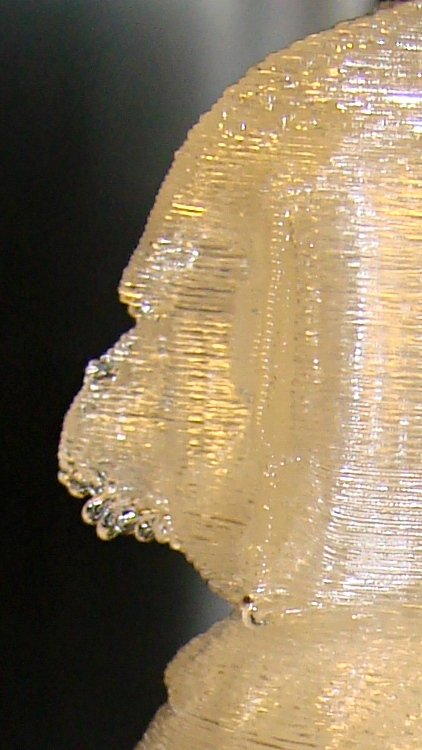
A closeup of the beak shows the crystal-clear drooping filament; a similar effect happened on the downward-pointing feather tips. Generally, this is a sign of too-hot extrusion, but at 165 °C I’m not convinced that’s applicable. It may simply be too much overhang at this scale:
M2 – cushwa Owl – beak detail
Overall, it’s pretty good. The config info doesn’t include the external perimeter speed, which I’ve been dialing back from an insanely high value. I think it was 75 for this one, which might be flinging the filament off the edge of the beak below that steep overhang.
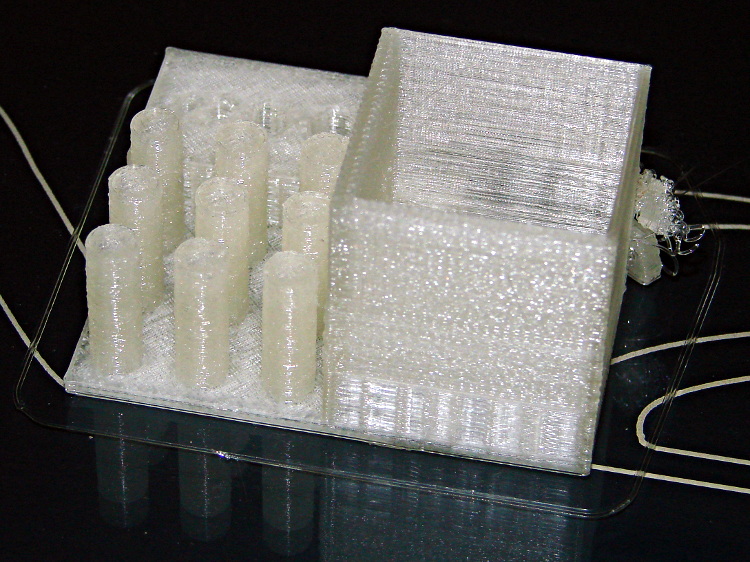
The arch foot broke loose from the platform after it grew to about 8 mm, but that seems to happen with most of the DIY printers. Apart from the tangle produced by that flaw, the rest of the object came out essentially perfect:
M2 – MAKE Magazine Torture Test – box and pillars
The surface finish is rougher than I think it should be, but the dense zigzag infill on the two thicker solid walls of the box seems to disturb their outer finish; the two thinner walls have linear fill and are fine.
Building these things seems to be the simplest and best way to figure out whether you have all the pieces flying in formation:
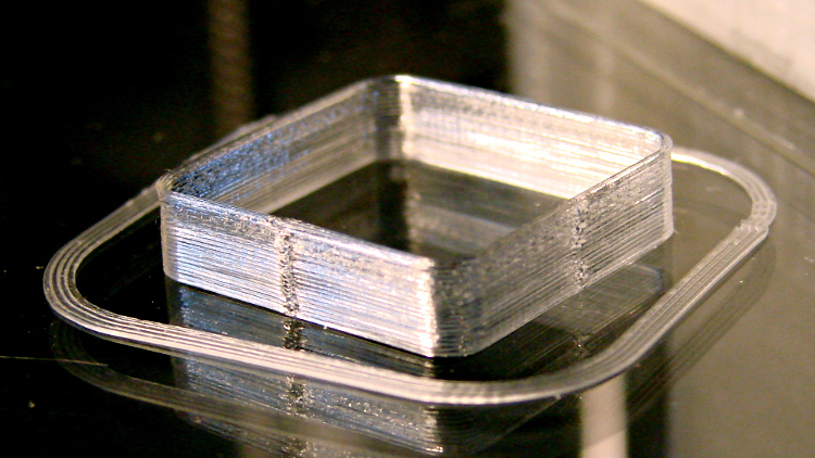
Thinwall box – first success
I took that picture after cracking them off the glass plate, then putting them back: the box really does line up with the skirt while printing. There’s another object visible in the background; that little box really was the first completely successful object.
It’s adapted from Coasterman’s classic calibration set, redone in OpenSCAD so it’s easy to modify. A pair of Minkowski sums produce two shapes that ensure the wall remains exactly one thread wide all the way around the perimeter.
When your printer can print one of these, then you can move on to more complex objects, secure in the knowledge that you’ve established:
Proper bed leveling and height setting: measure the skirt thickness
Both the layer thickness and width match your settings
Extrusion temperature: not too hot, not too cold
Printing speed / acceleration for all layers
First layer adhesion to platform
Minimum layer time to prevent melting / slumping
Filament diameter
Extrusion “packing density” multiplier: the fundamental fudge factor
Accurate steps/mm for all axes to get exact XYZ dimensions
Mechanical stability and rigidity
Basically, this object leaves no place for errors to hide. It doesn’t check infill, the various perimeter speeds, solid layers, and suchlike, but all the fundamentals must be correct or you’ll see painfully obvious flaws.
For example, there’s a bit of a zipper at the layer changes. It’s better than the Thing-O-Matic ever was, but it improved as I twiddled the Retraction settings on later objects.
No, the first few didn’t work quite that well:
M2 – Thinwall box with previous attempts
For what it’s worth, the last problem turned out to be a loose setscrew in the X axis motor pulley that produced a layer shift that closely resembled a stepper motor losing steps. All of the setscrews now sport a dab of low-strength Loctite, so that problem shouldn’t happen again.