Ed Nisley's Blog: Shop notes, electronics, firmware, machinery, 3D printing, laser cuttery, and curiosities. Contents: 100% human thinking, 0% AI slop.
A little more than two years after replacing its internal battery, the SJCAM M20 camera on my Tour Easy once again wouldn’t last to the end of the driveway if I forgot to turn on the external battery pack. This time around, the camera was so firmly jammed in the printed seat frame mount that I had to cut the mount apart.
Yup, that puppy is all swoll up:
SJCAM M20 swollen battery – side view
Poor thing looks like a tiny pillow:
SJCAM M20 swollen battery – pouch
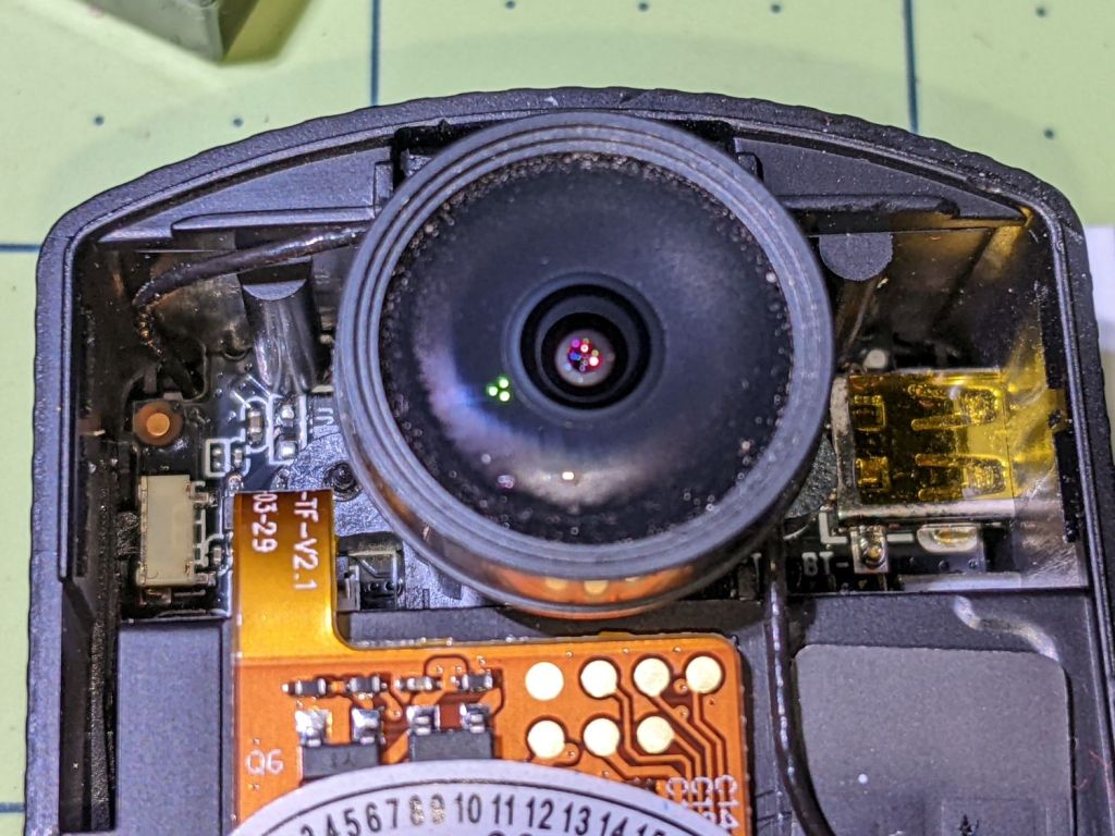
While I had it apart, I tried to clean / refurbish the button contacts on the top. Unfortunately, they’re pretty well buried in the camera frame and I was unwilling to dismantle the optics, remove the display, and gut the camera to find out if they were more accessible from the back surface:
SJCAM M20 – switch internals
While all that was going on, I ran off a new mount in white PETG:
SJCAM M20 – white case installed
I’m down to the last battery. The “4.35V” on the pillow indicates they’re special high-voltage lithium-polymer cells, so I can’t just drop a random lithium pouch cell in there and expect it to Just Work.
I think the “782633” is the cell size, so, if I were willing to have a few thousand on the shelf, a 552525 pouch might fit. The reduced capacity wouldn’t be a problem, as it must just keep the camera’s clock ticking between rides.
TIL: Muntin, which I’d always known was called a Mullion.
With that as preface, one of Mary’s quilting cronies lives in a very old house updated with vinyl windows sporting wood muntins arranged in a grille. The wood strips forming the grille end in plastic clips that snap into the sash, thereby holding the grill in place to make the window look more-or-less historically correct, while not being a dead loss as far as winter heating goes.
Time passed, sun-drenched plastic became brittle, and eventually enough clips broke that the grilles fell out. An afternoon quilting bee produced a question about the possibility of making a 3D printed clip, as the original manufacturer is either defunct or no longer offers that particular style of clip as a replacement part.
Well, I can do that:
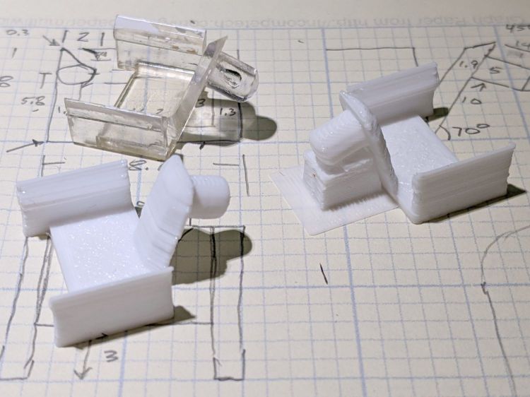
Window Muntin Clips
The original is (obviously) the transparent injection-molded part in the upper left. The other two come hot off the M2’s platform, with the one on the right showing the support material under the sash pin.
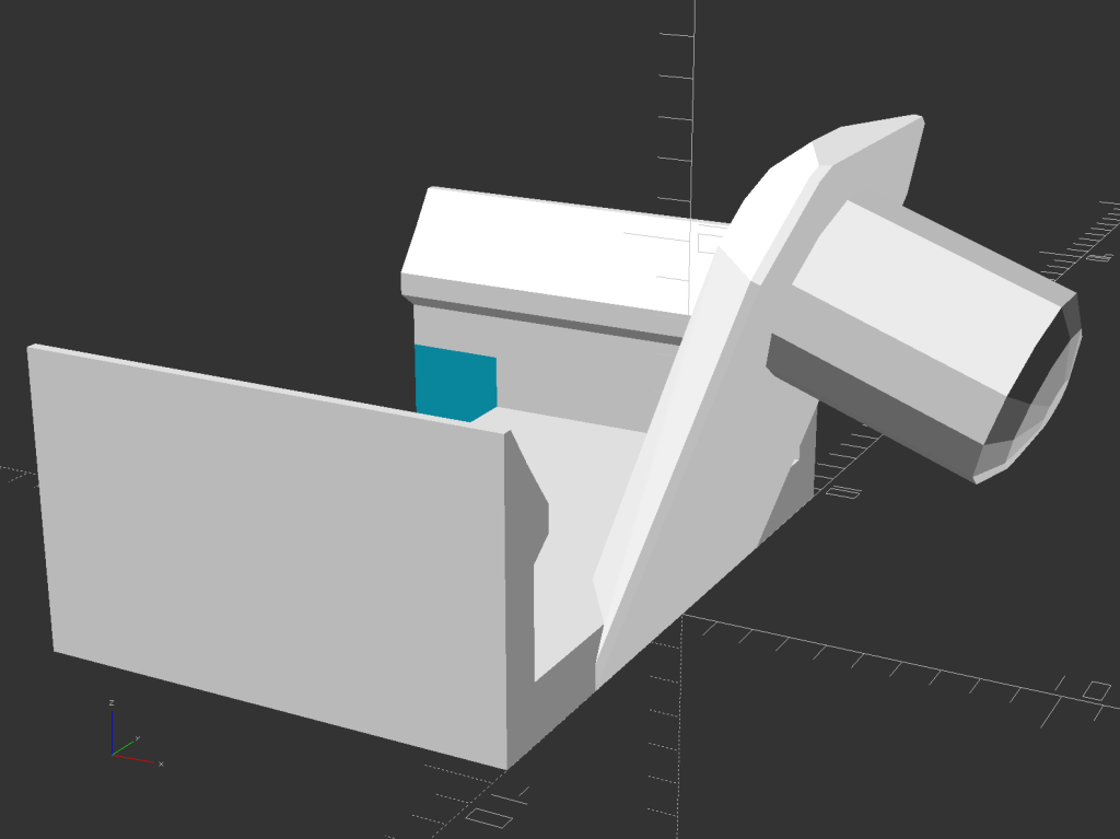
The solid model looks about like you’d expect:
Window Muntin Clip – solid model
There is obviously no way to build it without support material, so I painted the bottom facet of the sash pin with a PrusaSlicer support enforcer:
Window Muntin Clip – PrusaSlicer
The pin comes out slightly elongated top-to-bottom, but it’s still within the tolerances of the original part and ought to pop right into the sash. We’ll know how well it works shortly after the next quilting bee.
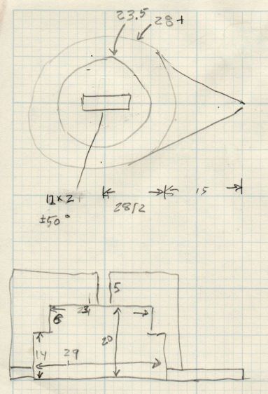
The doodle with useful measurements amid some ideas that did not work out:
This file contains hidden or bidirectional Unicode text that may be interpreted or compiled differently than what appears below. To review, open the file in an editor that reveals hidden Unicode characters.
Learn more about bidirectional Unicode characters
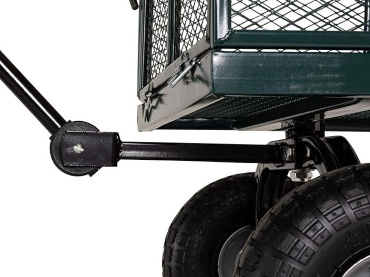
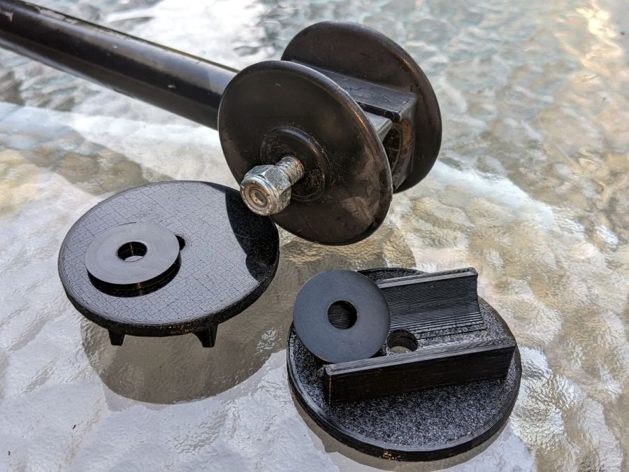
For reasons not relevant here, I was tapped to replace the plastic parts attaching the handle to a garden cart:
Garden Cart – handle attachment
The owner tried to contact the “manufacturer” to no avail; repair parts are simply not available, even if the name painted on the cart had a meaningful relationship to anything else.
Well, I can fix that:
Garden Cart – handle repair parts
Fortunately, another cart in the fleet provided the missing bits so I could reverse-engineer their measurements.
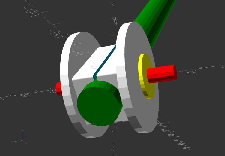
The solid model looks about like you’d expect:
Garden Cart Handle – show view
Printing the two halves with those nice (yellow) bosses in place wasn’t feasible. They were exactly 1 inch in diameter, so I just parted two cookies from the end of a stout acetal rod after drilling a hole for the 2-¼ inch 5/16-18 bolt.
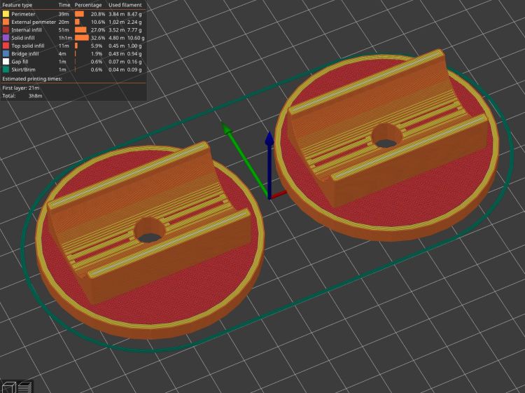
The two pieces took nigh onto three hours with five perimeters and 50% infill:
Garden Cart Handle – slicer preview
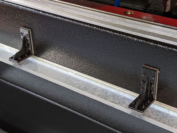
While delivering and installing the parts, I got volunteered to haul plants to cars with one of the carts during the upcoming Spring Plant Sale. That’ll teach me to stay in the Basement Shop …
This file contains hidden or bidirectional Unicode text that may be interpreted or compiled differently than what appears below. To review, open the file in an editor that reveals hidden Unicode characters.
Learn more about bidirectional Unicode characters
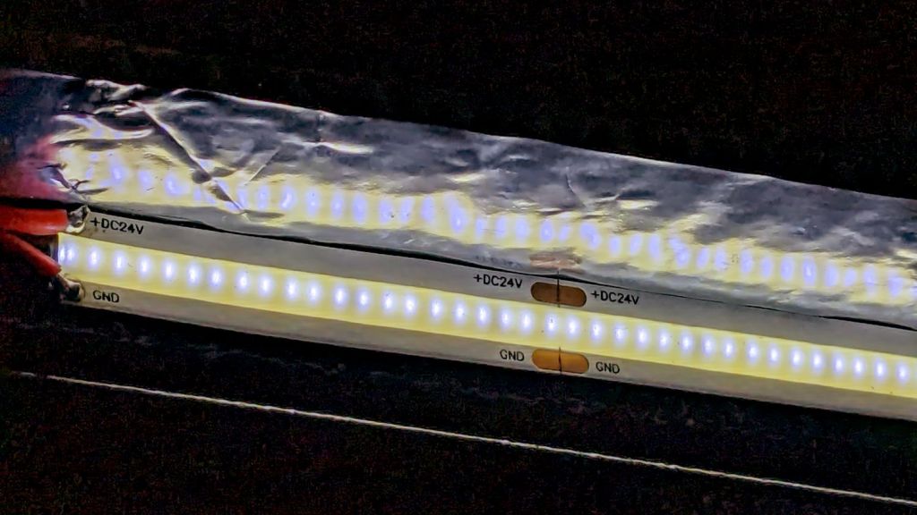
I cut new shades from vintage clear acrylic sheet, with more aluminized mylar attached to the lower surface: you can barely see the COB LED strip through the reflecting surface.
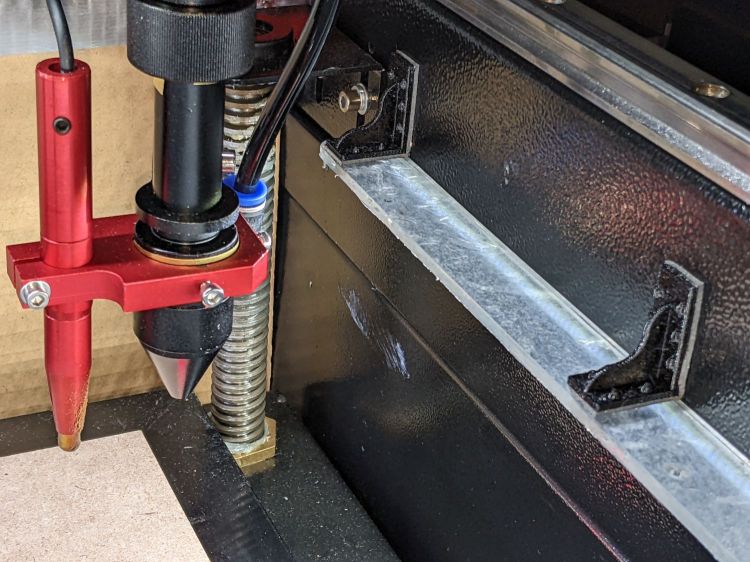
Depending on how you arrange all the hardware hanging on the nozzle, the shades can collide with something at the home position in the far right corner:
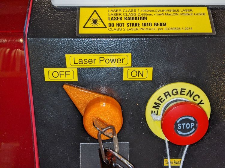
Although the OMTech laser controls the laser power supply with a key-lock switch, there’s little visible difference between the OFF and ON positions. Having occasionally mistaken it in both directions, this seemed like a useful addition:
Laser Power Lock Indicator – installed
The strip of black duct tape below the lock muffles the rattle of the triangle hatch key against the metal cabinet.
Two snippets of foam tape hold the knob to the lock cylinder, making an admittedly tenuous connection, but the knob fits around the outside of the switch housing with minimal clearance and doesn’t shouldn’t suffer any torque or pulling, so it might work.
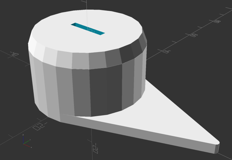
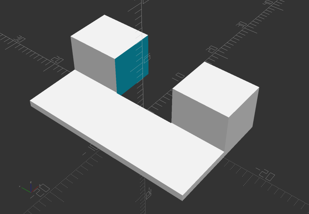
The solid model looks about like you’d expect:
Laser Power Lock Indicator – solid model
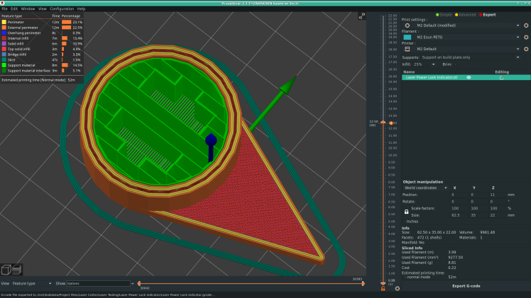
Unfortunately, it has no good orientation for printing, so I let PrusaSlicer generate support material inside the knob:
Laser Power Lock Indicator – Support structures
Suffice it to say: removing all that plastic did not go well.
I eventually grabbed the knob in the lathe and bored the interior out to its more-or-less proper dimensions, figuring nobody would ever notice the carnage, and it worked reasonably well. In the unlikely event I need another pointer, I’ll add a support spider to hold up the interior with minimal contact and less plastic.
Yeah, the laser really needs a stack light showing its condition and safety status …
This file contains hidden or bidirectional Unicode text that may be interpreted or compiled differently than what appears below. To review, open the file in an editor that reveals hidden Unicode characters.
Learn more about bidirectional Unicode characters
However, all that upward-directed light goes directly into my glare-sensitive eyeballs, so I added shades above the strips:
COB LED Shade – installed
They’re cut from corrugated cardboard because I have an essentially infinite supply and I’m still working out speeds and intensities. Eventually they’ll become something like black acrylic.
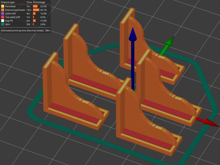
The brackets emerged from the vasty digital deep through the miracle of 3D printing:
COB LED Shade Brackets – slice preview
They’re stuck to the laser cabinet and the cardboard with double-sided duct tape. If you’re careful, they will line up along one edge of the tape, roll over neatly to stick their other face, then a single razor knife cut can separate each pair of neighbors.
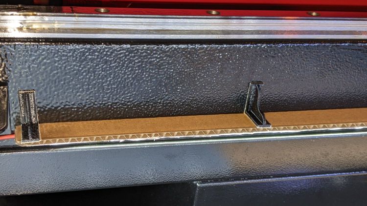
The underside sports an aluminized mylar strip to redirect the wasted light in a more useful direction:
COB LED Shade – aluminized Mylar reflector
The tapeless sticky shipped with the laser holds the reflector in place, while its 20 mm width sets the 21 mm shade dimension. Although you want a reasonably smooth layer, it need not be mirror-flat.
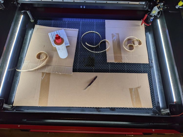
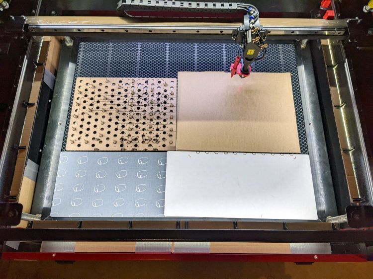
Now it’s really bright in there:
COB LED Shade – overview
While I had my head under the hood, I stuck a fourth strip of COB LEDs on the lip along the rear edge of the opening; it’s bright enough to cast the shadow just forward of the laser head despite the OEM under-gantry LED strip. Because the rear strip is aimed downward, it didn’t need a shade.
The perforated cardboard sheet on the left is a spike plate: more about that later.
This file contains hidden or bidirectional Unicode text that may be interpreted or compiled differently than what appears below. To review, open the file in an editor that reveals hidden Unicode characters.
Learn more about bidirectional Unicode characters
What used to be a “light box” had become a “light pad” powered through a USB Micro-B connector on the side. Unfortunately, the pad’s 5 mm thickness allows for very little mechanical reinforcement around the USB jack, while providing infinite opportunity to apply bending force. Over the course of the last half-dozen years (during which the price has dropped dramatically, despite recent events), the slightest motion flickered the LEDs.
So I squished the jack’s metal shell back into shape, found a short right-angle USB cable, and conjured a reinforcing fixture from the vasty digital deep:
LitUp LED Light Pad
The plate fits under the light pad, where a strip of super-sticky duct tape holds it in place:
LitUp Light Pad USB jack reinforcement – bottom
The USB plug fits between the two blocks with hot-melt glue holding it in place and filling the gap between the plug and the pad.
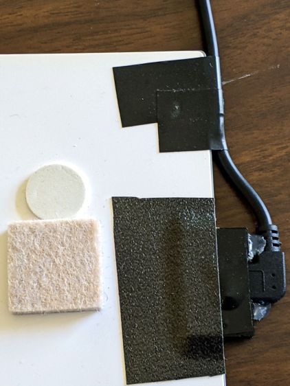
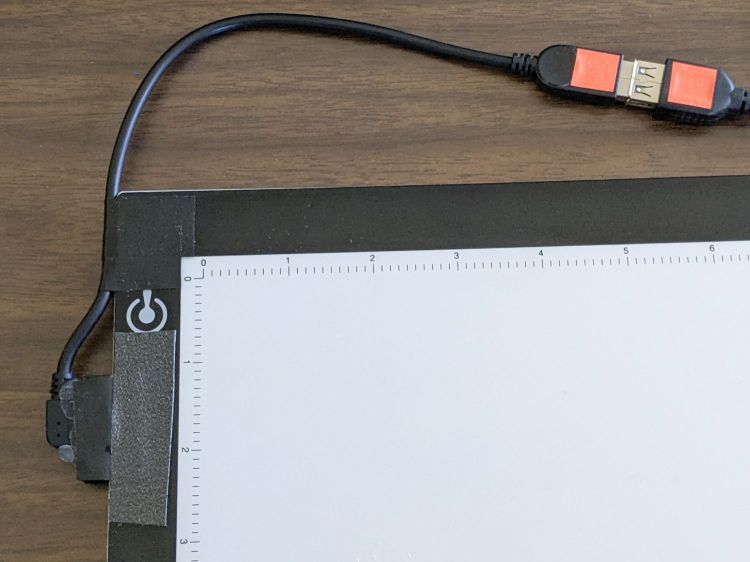
I’d like to say it’s more elegant than the cable redirection for my tablet, but anything involving black electrical tape and hot-melt glue just isn’t in the running for elegant:
LitUp Light Pad USB jack reinforcement – top
On the other paw, that socket ought to last pretty nearly forever, which counts for a whole lot more around here.
The retina-burn orange tape patches on the connector eliminate all the fumbling inherent to an asymmetric connector with invisible surface features. The USB wall wart on the other end of the cable sports similar markings.
This file contains hidden or bidirectional Unicode text that may be interpreted or compiled differently than what appears below. To review, open the file in an editor that reveals hidden Unicode characters.
Learn more about bidirectional Unicode characters


