There being nothing like a new problem to take one’s mind off all one’s old problems:
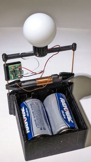
It’s a variation on the camera battery and AA alkaline holders for various blinky LEDs:
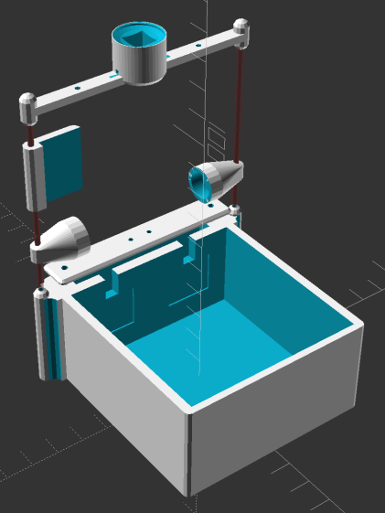
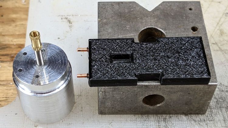
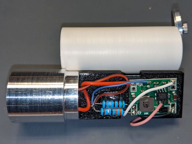
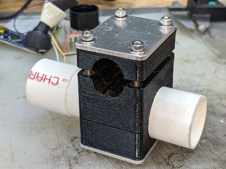
The little flag holding the C-Max CMMR-60 receiver PCB gets glued to the copper upright to keep it from swiveling in the breeze.
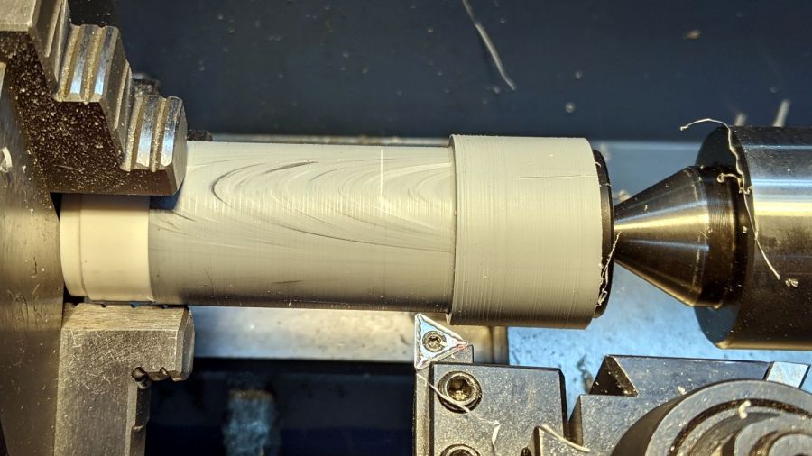
The conical caps on the ferrite bar antenna are glued to the uprights and the antenna, in the expectation this is a one-off build-only project.
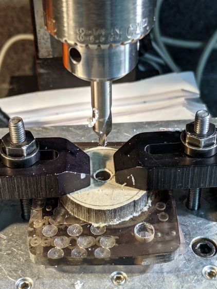
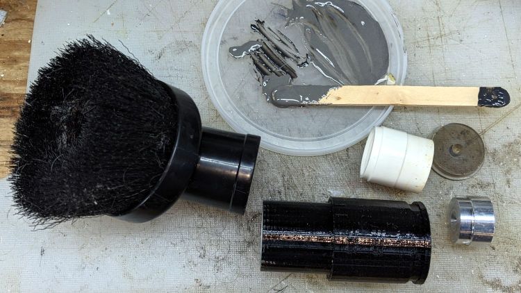
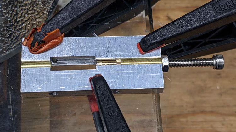
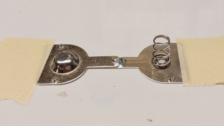
Rather than buy specialized D-cell contacts, I used 18650 lithium cell contacts and conjured the bridge by soldering two together:
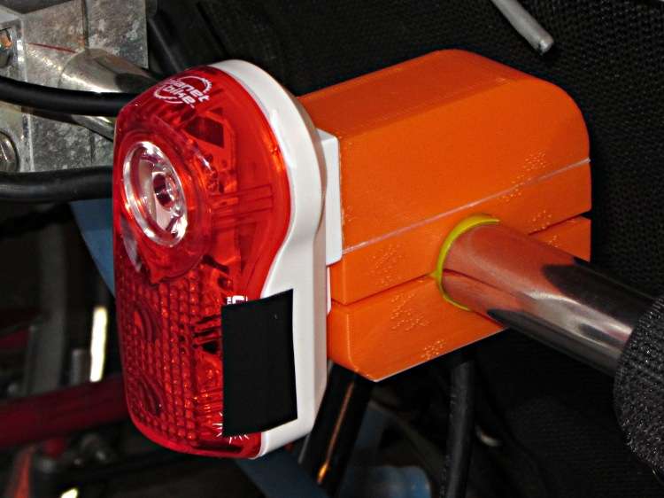
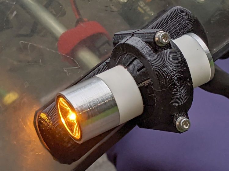
It sits on the windowsill, blinks quietly in the dark, and flickers invisibly during the daytime.
Those D cells came from the same batch that powered the previous version for the last five years, so they probably won’t last that long, even with a Nov 2024 date code.
C-Max is apparently out of the WWVB biz, but you can get a similar Canaduino AM WWVB receiver.
The far more complex EverSet ES100-MOD WWVB receiver requires a microcontroller with an I²C interface and very careful power management.
The OpenSCAD source code as a GitHub Gist:
| // Astable Multivibrator | |
| // Holder for Alkaline cells | |
| // Ed Nisley KE4ZNU August 2020 | |
| // 2020-09 add LED radome | |
| // 2020-11 add radome trim | |
| // 2021-11 D cells and WWVB receiver | |
| /* [Layout options] */ | |
| Layout = "Build"; // [Build,Show,Lid,Spider,AntCap,RecFlag] | |
| CellName = "AA"; // [AA, D] | |
| Struts = -1; // [0:None, -1:Dual, 1:Quad] | |
| WWVB = true; | |
| /* [Hidden] */ | |
| NumCells = 2; // [2] | |
| // Extrusion parameters | |
| /* [Hidden] */ | |
| ThreadThick = 0.25; | |
| ThreadWidth = 0.40; | |
| HoleWindage = 0.2; | |
| function IntegerMultiple(Size,Unit) = Unit * ceil(Size / Unit); | |
| function IntegerLessMultiple(Size,Unit) = Unit * floor(Size / Unit); | |
| Protrusion = 0.1; // make holes end cleanly | |
| inch = 25.4; | |
| //- Basic dimensions | |
| WallThick = IntegerMultiple(3.0,ThreadWidth); | |
| CornerRadius = WallThick/2; | |
| FloorThick = IntegerMultiple(3.0,ThreadThick); | |
| TopThick = IntegerMultiple(2.0,ThreadThick); | |
| WireOD = 1.5; // battery & LED wiring | |
| WireOC = 8.0; // hole spacing in lid | |
| Gap = 5.0; | |
| // Cylindrical cell sizes | |
| // https://en.wikipedia.org/wiki/List_of_battery_sizes#Cylindrical_batteries | |
| CELL_NAME = 0; | |
| CELL_OD = 1; | |
| CELL_OAL = 2; | |
| // FIXME search() needs special-casing to properly find AAA and AAAA | |
| // Which is why CellName is limited to AA | |
| CellData = [ | |
| ["AAAA",8.3,42.5], | |
| ["AAA",10.5,44.5], | |
| ["AA",14.5,50.5], | |
| ["C",26.2,50], | |
| ["D",34.2,61.5], | |
| ["A23",10.3,28.5], | |
| ["CR123A",17.0,34.5], | |
| ["18650",18.8,65.2], // bare 18650 with button end | |
| ["18650Prot",19.0,70.0], // protected 18650 = 19670 plus a bit | |
| ]; | |
| CellIndex = search([CellName],CellData,1,0)[0]; | |
| echo(str("Cell index: ",CellIndex," = ",CellData[CellIndex][CELL_NAME])); | |
| //- Contact dimensions | |
| CONTACT_NAME = 0; | |
| CONTACT_WIDE = 1; | |
| CONTACT_HIGH = 2; | |
| CONTACT_THICK = 3; // plate thickness | |
| CONTACT_TIP = 4; // tip to rear face | |
| CONTACT_TAB = 5; // solder tab width | |
| ContactData = [ | |
| ["AA+",12.2,12.2,0.3,1.7,3.5], // pos bump | |
| ["AA-",12.2,12.2,0.3,5.0,3.5], // half-compressed neg spring | |
| ["AA+-",28.2,12.2,0.3,5.0,0], // pos-neg bridge | |
| ["D+",18.5,16.0,0.3,2.8,5.5], | |
| ["D-",18.5,16.0,0.3,6.0,5.5], | |
| ["D+-",50.0,19.0,0.3,7.0,0], // solder +/- tabs together | |
| ["Li+",18.5,16.0,0.3,2.8,5.5], | |
| ["Li-",18.5,16.0,0.3,6.0,5.5], | |
| ]; | |
| function ConDat(name,dim) = ContactData[search([name],ContactData,1,0)[0]][dim]; | |
| ContactRecess = 2*ConDat(str(CellName,"+"),CONTACT_THICK); | |
| ContactOC = CellData[CellIndex][CELL_OD]; | |
| WireBay = 6.0; // room for wiring to contacts | |
| //- Wire struts | |
| StrutDia = 1.6; // AWG 14 = 1.6 mm | |
| StrutSides = 3*4; | |
| ID = 0; | |
| OD = 1; | |
| LENGTH = 2; | |
| StrutBase = [StrutDia,StrutDia + 2*5*ThreadWidth, // ID = wire, OD = buildable | |
| FloorThick + CellData[CellIndex][CELL_OD]]; // LENGTH = base is flush with cell top | |
| //- Holder dimensions | |
| BatterySize = [CellData[CellIndex][CELL_OAL] + // cell | |
| ConDat(str(CellName,"+"),CONTACT_TIP) + // pos contact | |
| ConDat(str(CellName,"-"),CONTACT_TIP) – // neg contact | |
| 2*ContactRecess, // sink into wall | |
| NumCells*CellData[CellIndex][CELL_OD], | |
| CellData[CellIndex][CELL_OD] | |
| ]; | |
| echo(str("Battery space: ",BatterySize)); | |
| CaseSize = [3*WallThick + // end walls + wiring partition | |
| BatterySize.x + // cell | |
| WireBay, // wiring bay | |
| 2*WallThick + BatterySize.y, | |
| FloorThick + BatterySize.z | |
| ]; | |
| echo(str("CaseSize: ",CaseSize)); | |
| BatteryOffset = (CaseSize.x – (2*WallThick + | |
| CellData[CellIndex][CELL_OAL] + | |
| ConDat(str(CellName,"-"),CONTACT_TIP)) | |
| ) /2 ; | |
| ThumbRadius = 0.75 * CaseSize.z; | |
| StrutOC = [IntegerLessMultiple(CaseSize.x – 2*CornerRadius -2*StrutBase[OD],5.0), | |
| IntegerMultiple(CaseSize.y + StrutBase[OD],5.0)]; | |
| StrutAngle = atan(StrutOC.y/StrutOC.x); | |
| echo(str("Strut OC: ",StrutOC)); | |
| LidSize = [2*WallThick + WireBay + ConDat(str(CellName,"+"),CONTACT_THICK), CaseSize.y, FloorThick/2]; | |
| LidScrew = [2.0,3.8,7.0]; // M2 pan head screw (LENGTH = threaded) | |
| LidScrewOC = CaseSize.y/2 – CornerRadius – LidScrew[OD]; // allow space around screw head | |
| //- Piranha LEDs | |
| PiranhaBody = [8.0,8.0,8.0]; // Z = heatsink fins + plastic body + lens | |
| PiranhaPin = 0.0; // trimmed pin length beyond heatsink | |
| PiranhaPinsOC = [5.0,5.0]; // pin XY distance | |
| PiranhaRecess = PiranhaBody.z + PiranhaPin/2; // minimum LED recess depth | |
| BallOD = 40.0; // radome sphere | |
| BallSides = 4*3*4; // nice smoothness | |
| PillarOD = norm([PiranhaBody.x,PiranhaBody.y]) + 2*WallThick; | |
| BallChordM = BallOD/2 – sqrt(pow(BallOD/2,2) – (pow(PillarOD,2))/4); | |
| echo(str("Ball chord depth: ",BallChordM)); | |
| RadomePillar = [norm([PiranhaBody.x,PiranhaBody.y]), // ID = LED diagonal | |
| PillarOD, | |
| FloorThick + PiranhaRecess + BallChordM]; // height to top of ball chord | |
| echo(str("Pillar: ",RadomePillar)); | |
| RadomeBar = [StrutBase[OD]*cos(180/StrutSides),StrutOC.y,StrutBase[OD]/2]; | |
| Tape = [RadomePillar[ID],16.0,1.0]; // sticky tape disk, OD to match hole punch | |
| //- WWVB receiver hardware | |
| Antenna = [10.0 + 0.5,14.0,60.0 + 2.0]; // ferrite antenna bar with clearance | |
| AntCapSize = [Antenna[ID] + 1.0,Antenna[OD],5.0]; // LENGTH=insertion | |
| RecPCB = [24.0,16.0,5.0]; | |
| //———————- | |
| // Useful routines | |
| module PolyCyl(Dia,Height,ForceSides=0) { // based on nophead's polyholes | |
| Sides = (ForceSides != 0) ? ForceSides : (ceil(Dia) + 2); | |
| FixDia = Dia / cos(180/Sides); | |
| cylinder(r=(FixDia + HoleWindage)/2,h=Height,$fn=Sides); | |
| } | |
| // Spider for single LED atop struts, with the ball | |
| module DualSpider() { | |
| difference() { | |
| union() { | |
| for (j=[-1,1]) { | |
| for (k=[-1,1]) | |
| translate([0,j*StrutOC.y/2,k*RadomeBar.z]) | |
| rotate(180/StrutSides) | |
| sphere(d=StrutBase[OD]/cos(180/StrutSides),$fn=StrutSides); | |
| translate([0,j*StrutOC.y/2,0]) | |
| rotate(180/StrutSides) | |
| cylinder(d=StrutBase[OD],h=2*RadomeBar.z,center=true,$fn=StrutSides); | |
| } | |
| cube(RadomeBar,center=true); // connecting bar | |
| cylinder(d=RadomePillar[OD],h=RadomePillar[LENGTH],$fn=BallSides); | |
| translate([0,0,-RadomeBar.z/2]) | |
| cylinder(d1=0.9*RadomePillar[OD],d2=RadomePillar[OD],h=RadomeBar.z/2,$fn=BallSides); | |
| } | |
| for (j=[-1,1]) // strut wires | |
| translate([0,j*StrutOC.y/2,-3*StrutBase[OD]/2]) | |
| rotate(180/StrutSides) | |
| PolyCyl(StrutBase[ID],2*StrutBase[OD],StrutSides); | |
| for (k=[-1,1]) // LED wiring through bar | |
| translate([0,k*(StrutOC.x/2 – 2*RadomeBar.x),-RadomeBar.z]) | |
| rotate(180/6) | |
| PolyCyl(StrutBase[ID],2*RadomeBar.z,6); | |
| translate([0,0,BallOD/2 + RadomePillar[LENGTH] – BallChordM]) // ball inset | |
| sphere(d=BallOD); | |
| translate([0,0,BallOD/2 + RadomePillar[LENGTH] – BallChordM – Tape[LENGTH]/2]) // tape inset | |
| intersection() { | |
| sphere(d=BallOD); | |
| cylinder(d=Tape[OD],h=2*BallOD,center=true); | |
| } | |
| translate([0,0,RadomePillar.z – PiranhaRecess + RadomePillar.z/2]) // LED inset | |
| cube(PiranhaBody + [HoleWindage,HoleWindage,RadomePillar.z],center=true); // XY clearance | |
| translate([0,0,StrutBase[OD]/4 + WireOD/2 + 0*Protrusion]) // wire channels | |
| cube([WireOD,RadomePillar[OD] + 2*WallThick,WireOD],center=true); | |
| } | |
| } | |
| //– WWVB antenna support cap | |
| module AntennaBar() { | |
| rotate([90,0,0]) | |
| union() { | |
| cylinder(d=Antenna[ID],h=Antenna[LENGTH],$fn=BallSides,center=true); | |
| cylinder(d=2*Antenna[OD],h=Antenna[LENGTH] – 2*AntCapSize[LENGTH],$fn=BallSides,center=true); | |
| } | |
| } | |
| module AntennaCap() { | |
| rotate([90,0,0]) | |
| intersection() { | |
| translate([0,-Antenna[LENGTH]/2 + AntCapSize[LENGTH],0]) | |
| difference() { | |
| hull() { | |
| rotate([90,0,0]) | |
| cylinder(d=AntCapSize[OD],h=Antenna[LENGTH],$fn=BallSides,center=true); | |
| for (j=[-1,1]) | |
| translate([0,j*StrutOC.y/2,0]) | |
| rotate(180/StrutSides) | |
| cylinder(d=StrutBase[OD],h=1*StrutBase[OD],$fn=StrutSides,center=true); | |
| } | |
| for (j=[-1,1]) | |
| translate([0,j*StrutOC.y/2,-Antenna[OD]/2]) | |
| rotate(180/StrutSides) | |
| PolyCyl(StrutBase[ID],Antenna[OD],StrutSides); | |
| AntennaBar(); | |
| } | |
| rotate([-90,0,0]) | |
| cylinder(d=Antenna[OD],h=Antenna[LENGTH],center=false); | |
| } | |
| } | |
| //– WWVB PCB support flag | |
| module RecFlag() { | |
| difference() { | |
| hull() { | |
| rotate(180/StrutSides) | |
| cylinder(d=StrutBase[OD],h=RecPCB.x,$fn=StrutSides); | |
| translate([0,RecPCB.y,0]) | |
| rotate(180/StrutSides) | |
| cylinder(d=StrutBase[OD],h=RecPCB.x,$fn=StrutSides); | |
| } | |
| translate([0,0,-Protrusion]) | |
| rotate(180/StrutSides) | |
| PolyCyl(StrutBase[ID],2*RecPCB.x,StrutSides); | |
| translate([0,StrutBase[OD]/2,-Protrusion]) | |
| cube([StrutBase[OD],RecPCB.y,2*RecPCB.x],center=false); | |
| } | |
| } | |
| //– Overall case with origin at battery center | |
| module Case() { | |
| union() { | |
| difference() { | |
| union() { | |
| hull() | |
| for (i=[-1,1], j=[-1,1]) | |
| translate([i*(CaseSize.x/2 – CornerRadius), | |
| j*(CaseSize.y/2 – CornerRadius), | |
| 0]) | |
| cylinder(r=CornerRadius/cos(180/8),h=CaseSize.z,$fn=8); // cos() fixes undersize spheres! | |
| if (Struts) | |
| for (i = (Struts == 1) ? [-1,1] : -1) { // strut bases | |
| hull() | |
| for (j=[-1,1]) | |
| translate([i*StrutOC.x/2,j*StrutOC.y/2,0]) | |
| rotate(180/StrutSides) | |
| cylinder(d=StrutBase[OD],h=StrutBase[LENGTH],$fn=StrutSides); | |
| translate([i*StrutOC.x/2,0,StrutBase[LENGTH]/2]) | |
| cube([2*StrutBase[OD],StrutOC.y,StrutBase[LENGTH]],center=true); // blocks for fairing | |
| for (j=[-1,1]) // hemisphere caps | |
| translate([i*StrutOC.x/2, | |
| j*StrutOC.y/2, | |
| StrutBase[LENGTH]]) | |
| rotate(180/StrutSides) | |
| sphere(d=StrutBase[OD]/cos(180/StrutSides),$fn=StrutSides); | |
| } | |
| } | |
| translate([BatteryOffset,0,BatterySize.z/2 + FloorThick]) // cells | |
| cube(BatterySize + [0,0,Protrusion],center=true); | |
| translate([BatterySize.x/2 + BatteryOffset + ContactRecess/2 – Protrusion/2, // contacts | |
| 0, | |
| BatterySize.z/2 + FloorThick]) | |
| cube([ContactRecess + Protrusion, | |
| ConDat(str(CellName,"+-"),CONTACT_WIDE), | |
| ConDat(str(CellName,"+-"),CONTACT_HIGH) | |
| ],center=true); | |
| translate([-(BatterySize.x/2 – BatteryOffset + ContactRecess/2 – Protrusion/2), | |
| ContactOC/2, | |
| BatterySize.z/2 + FloorThick]) | |
| cube([ContactRecess + Protrusion, | |
| ConDat(str(CellName,"+"),CONTACT_WIDE), | |
| ConDat(str(CellName,"+"),CONTACT_HIGH) | |
| ],center=true); | |
| translate([-(BatterySize.x/2 – BatteryOffset + ContactRecess/2 – Protrusion/2), | |
| -ContactOC/2, | |
| BatterySize.z/2 + FloorThick]) | |
| cube([ContactRecess + Protrusion, | |
| ConDat(str(CellName,"-"),CONTACT_WIDE), | |
| ConDat(str(CellName,"-"),CONTACT_HIGH) | |
| ],center=true); | |
| translate([-CaseSize.x/2 + WireBay/2 + WallThick, // wire bay with screw bosses | |
| 0, | |
| BatterySize.z/2 + FloorThick + Protrusion/2]) | |
| cube([WireBay, | |
| 2*LidScrewOC – LidScrew[ID] – 2*4*ThreadWidth, | |
| BatterySize.z + Protrusion | |
| ],center=true); | |
| for (j=[-1,1]) // screw holes | |
| translate([-CaseSize.x/2 + WireBay/2 + WallThick, | |
| j*LidScrewOC, | |
| CaseSize.z – LidScrew[LENGTH] + Protrusion]) | |
| PolyCyl(LidScrew[ID],LidScrew[LENGTH],6); | |
| for (j=[-1,1]) | |
| translate([-(BatterySize.x/2 – BatteryOffset + WallThick/2), // contact tabs | |
| j*ContactOC/2, | |
| BatterySize.z + FloorThick – Protrusion]) | |
| cube([2*WallThick, | |
| ConDat(str(CellName,"+"),CONTACT_TAB), | |
| (BatterySize.z – ConDat(str(CellName,"+"),CONTACT_HIGH)) | |
| ],center=true); | |
| if (false) | |
| translate([0,0,CaseSize.z]) // finger cutout | |
| rotate([90,00,0]) | |
| cylinder(r=ThumbRadius,h=2*CaseSize.y,center=true,$fn=22); | |
| if (Struts) | |
| for (i2 = (Struts == 1) ? [-1,1] : -1) { // strut wire holes and fairing | |
| for (j=[-1,1]) | |
| translate([i2*StrutOC.x/2,j*StrutOC.y/2,FloorThick]) | |
| rotate(180/StrutSides) | |
| PolyCyl(StrutBase[ID],2*StrutBase[LENGTH],StrutSides); | |
| for (i=[-1,1], j=[-1,1]) // fairing cutaways | |
| translate([i*StrutBase[OD] + (i2*StrutOC.x/2), | |
| j*StrutOC.y/2, | |
| -Protrusion]) | |
| rotate(180/StrutSides) | |
| PolyCyl(StrutBase[OD],StrutBase[LENGTH] + 2*Protrusion,StrutSides); | |
| } | |
| translate([0,0,ThreadThick – Protrusion]) // recess around name | |
| cube([51.0,15,2*ThreadThick],center=true); | |
| } | |
| linear_extrude(height=2*ThreadThick + Protrusion,convexity=10) { | |
| translate([0,-3.5,0]) | |
| mirror([0,1,0]) | |
| text(text="softsolder",size=6,spacing=1.20,font="Arial:style:Bold",halign="center",valign="center"); | |
| translate([0,3.5,0]) | |
| mirror([0,1,0]) | |
| text(text=".com",size=6,spacing=1.20,font="Arial:style:Bold",halign="center",valign="center"); | |
| } | |
| } | |
| } | |
| module Lid() { | |
| difference() { | |
| hull() | |
| for (i=[-1,1], j=[-1,1], k=[-1,1]) | |
| translate([i*(LidSize.x/2 – CornerRadius), | |
| j*(LidSize.y/2 – CornerRadius), | |
| k*(LidSize.z – CornerRadius)]) // double thickness for flat bottom | |
| sphere(r=CornerRadius/cos(180/8),$fn=8); | |
| translate([0,0,-LidSize.z]) // remove bottom | |
| cube([(LidSize.x + 2*Protrusion),(LidSize.y + 2*Protrusion),2*LidSize.z],center=true); | |
| for (j=[-1,1]) // wire holes | |
| translate([0,j*WireOC/2,-Protrusion]) | |
| PolyCyl(WireOD,2*LidSize.z,6); | |
| for (j=[-1,1]) | |
| translate([0,j*LidScrewOC,-Protrusion]) | |
| PolyCyl(LidScrew[ID],2*LidSize.z,6); | |
| } | |
| } | |
| //——————- | |
| // Show & build stuff | |
| if (Layout == "Case") | |
| Case(); | |
| if (Layout == "Lid") | |
| Lid(); | |
| if (Layout == "AntCap") | |
| AntennaCap(); | |
| if (Layout == "RecFlag") | |
| RecFlag(); | |
| if (Layout == "Spider") | |
| if (Struts == -1) | |
| DualSpider(); | |
| else | |
| cube(10,center=true); | |
| if (Layout == "Build") { | |
| rotate(90) | |
| Case(); | |
| translate([0,-(CaseSize.x/2 + LidSize.x/2 + Gap),0]) | |
| rotate(90) | |
| Lid(); | |
| if (Struts == -1) { | |
| difference() { | |
| union() { | |
| translate([CaseSize.x/2 + RadomePillar[OD],0,0]) | |
| DualSpider(); | |
| translate([-(CaseSize.x/2 + RadomePillar[OD]),0,0]) | |
| rotate([180,0,0]) | |
| DualSpider(); | |
| } | |
| translate([0,0,-2*CaseSize.z]) | |
| rotate(90) | |
| cube(4*CaseSize,center=true); | |
| } | |
| } | |
| if (WWVB) { | |
| for (i=[-1,1]) | |
| translate([i*(Antenna[LENGTH]/2 – AntCapSize[LENGTH]),CaseSize.x/2 + Antenna[OD],0]) | |
| AntennaCap(); | |
| translate([0,CaseSize.x/2 + Antenna[OD],0]) | |
| RecFlag(); | |
| } | |
| } | |
| if (Layout == "Show") { | |
| Case(); | |
| for (j=[-1,1]) | |
| color("Brown",0.3) | |
| translate([-StrutOC.x/2,j*StrutOC.y/2,Protrusion]) | |
| cylinder(d=StrutDia[ID],h=3*CaseSize.z,$fn=StrutSides); | |
| translate([-(CaseSize.x/2 – LidSize.x/2),0,(CaseSize.z + Gap)]) | |
| Lid(); | |
| if (Struts == -1) | |
| translate([-StrutOC.x/2,0,3*CaseSize.z]) | |
| DualSpider(); | |
| if (WWVB) { | |
| for (j=[-1,1]) | |
| translate([-StrutOC.x/2,,j*(Antenna[LENGTH]/2 – AntCapSize[LENGTH]),1.5*CaseSize.z]) | |
| rotate([-j*90,0,0]) | |
| AntennaCap(); | |
| translate([-StrutOC.x/2,,-(StrutOC.y/2),2*CaseSize.z]) | |
| RecFlag(); | |
| } | |
| } | |