The Smell of Molten Projects in the Morning

Ed Nisley's Blog: Shop notes, electronics, firmware, machinery, 3D printing, laser cuttery, and curiosities. Contents: 100% human thinking, 0% AI slop.

Tag: M2

Using and tweaking a Makergear M2 3D printer

  • Tour Easy: SJCAM C100+ Mount

    Tour Easy: SJCAM C100+ Mount

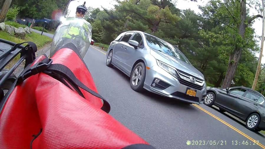
    The batteries (which are no longer available) and the control buttons have worn out on the SJCAM M20 camera on the back of my Tour Easy, so a replacement is in order:

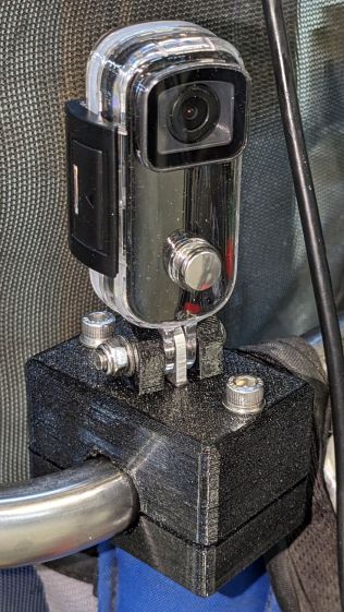
    Tour Easy - SJCAM C100 mount - installed
    Tour Easy – SJCAM C100 mount – installed

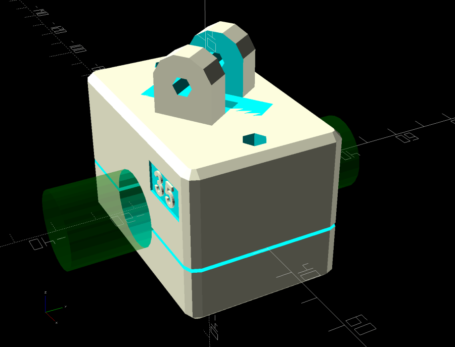
    It’s an SJCAM C100+ in its waterproof housing, screwed to a block descended from the M20 mount:

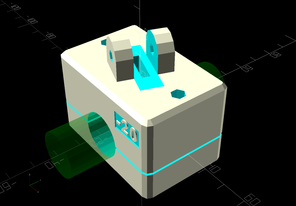
    SJCAM C100 Mount - solid model
    SJCAM C100 Mount – solid model

    The C100+ has a non-replaceable lithium pouch battery that may not last for the hour or so we generally ride, but at least this is a starting point for seeing how the thing works.

    The PrusaSlicer preview shows the support structure inside the seat rail arches:

    SJCAM C100 Mount - slicer
    SJCAM C100 Mount – slicer

    That appears under the four central facets of each arch, where I “painted” the support enforcers, because the automagic supports fill the entire arch and are basically impossible to pry off.

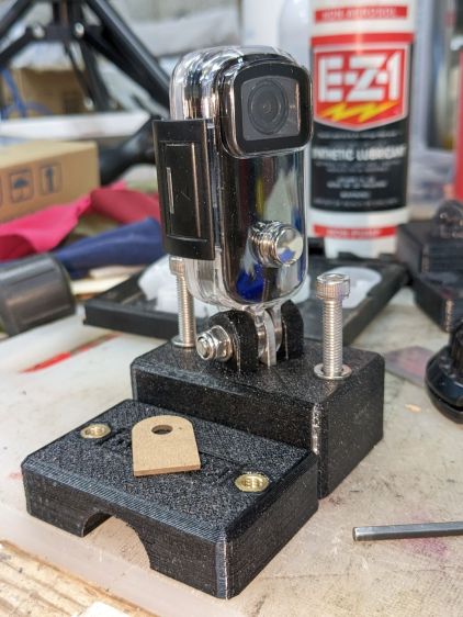
    The hole between the ears on the top holds an aluminum tab intended to diffuse the wobble from that tall camera. A laser-cut chipboard template simplified drilling & cutting the tab from an aluminum sheet:

    Tour Easy - SJCAM C100 mount - test fit
    Tour Easy – SJCAM C100 mount – test fit

    The tab and the brass inserts are held in place with JB Weld Plastic Bonder, my new go-to adhesive for such things.

    The camera includes WiFi and the inevitable app lets you download images without opening the case. Because I’ll be charging the camera after each ride, I may as well just haul the whole thing inside, plug it into a USB port, and proceed as before.

    For future reference, the manual details the operating modes:

    SJCAM C100 Manual - Modes
    SJCAM C100 Manual – Modes

    Because the camera powers up with WiFi enabled and I have no plans to communicate with it while riding, the startup sequence will be:

    • Long-press to power on
    • Double-click to disable WiFi
    • Single-click to start recording

    The OpenSCAD source code as a GitHub Gist:

    // SJCAM C100+ Camera Mount for Tour Easy seat back rail
    // Ed Nisley – KE4ZNU
    // 2023-04
    /* [Layout Options] */
    LookAngle = -20; // camera angle, looking backwards = 0°
    Layout = "Show"; // [Show,Build]
    /* [Hidden] */
    ThreadWidth = 0.40;
    ThreadThick = 0.25;
    HoleWindage = 0.2;
    Protrusion = 0.1;
    ID = 0;
    OD = 1;
    LENGTH = 2;
    //—–
    // Dimensions
    ClampScrew = [5.0,10.0,40.0]; // ID=thread OD=washer LENGTH=total
    ClampInsert = [5.0,7.5,10.5]; // brass insert
    MountScrew = [5.0,10.0,23.0]; // ID=thread OD=washer LENGTH=under nut
    MountInsert = [5.0,7.5,10.5]; // ID=screw OD, OD=knurl dia
    EmbossDepth = 2*ThreadThick + Protrusion; // recess depth + Protrusion beyond surface
    DebossHeight = EmbossDepth; // text height + Protrusion into part
    RailOD = 20.0; // slightly elliptical in bent section
    RailSides = 2*3*4;
    ClampOA = [60.0,40.0,ClampScrew[LENGTH]]; // set clamp size to avoid weird screw spacing
    echo(ClampOA = ClampOA);
    ClampScrewOC = IntegerMultiple(ClampOA.x – ClampScrew[OD] – 10*ThreadWidth,1.0);
    echo(ClampScrewOC = ClampScrewOC);
    ClampOffset = 5.0; // in case we need more room on top
    ClampRadius = 3.0;
    ClampSides = 8;
    Kerf = 1.0; // slice through the middle
    // center mount blade, Z = depth into block
    MountBlade = [15.0 + 2*HoleWindage,
    3.0 + 2*HoleWindage,
    (ClampOA.z – RailOD + ClampOffset)/2 – 4*ThreadThick + Protrusion];
    echo(MountBlade = MountBlade);
    MountRadius = MountBlade.x / 2;
    MountGap = 9.5; // camera mount gap around center blade
    MountOffset = [0,0,7.0]; // mount hole offset from block surface
    FadeColor = "Green";
    FadeAlpha = 0.25;
    //—–
    // Useful routines
    function IntegerMultiple(Size,Unit) = Unit * ceil(Size / Unit);
    module PolyCyl(Dia,Height,ForceSides=0) { // based on nophead's polyholes
    Sides = (ForceSides != 0) ? ForceSides : (ceil(Dia) + 2);
    FixDia = Dia / cos(180/Sides);
    cylinder(r=(FixDia + HoleWindage)/2,
    h=Height,
    $fn=Sides);
    }
    //—–
    // Clamp
    // Grips seat frame rail
    // Origin at middle of seat rail, X rearward, Y parallel to seat frame rail
    // Block offset raises whole thing
    module Clamp() {
    difference() {
    translate([0,0,ClampOffset]) {
    difference() {
    union() {
    hull() // the main block
    for (i=[-1,1], j=[-1,1], k=[-1,1])
    translate([i*(ClampOA.x – 2*ClampRadius)/2,
    j*(ClampOA.y – 2*ClampRadius)/2,
    k*(ClampOA.z – 2*ClampRadius)/2])
    sphere(r=ClampRadius/cos(180/ClampSides),$fn=ClampSides);
    hull() // camera mount boss
    for (k=[0,1])
    translate([0,0,k*(MountOffset.z) + ClampOA.z/2])
    rotate([0,90,LookAngle + 90]) rotate(180/12)
    cylinder(r=MountRadius,h=MountScrew[LENGTH],center=true,$fn=12);
    }
    for (i=[-1,1]) // clamp inserts
    translate([i*ClampScrewOC/2,0,-(ClampOA.z/2 + Protrusion)])
    rotate(180/6)
    PolyCyl(ClampInsert[OD],ClampInsert[LENGTH],6);
    for (i=[-1,1]) // clamp screw holes
    translate([i*ClampScrewOC/2,0,-ClampOA.z])
    rotate(180/6)
    PolyCyl(ClampScrew[ID],2*ClampOA.z,6);
    translate([0,0,ClampOA.z/2 – (MountBlade.z/2 – Protrusion/2)]) // camera center blade
    rotate(LookAngle)
    cube(MountBlade,center=true);
    rotate(LookAngle + 90) // camera mount boss slot
    translate([0,0,ClampOA.z/2 + 2*MountRadius])
    cube([MountGap,4*MountRadius,4*MountRadius],center=true);
    translate([0,0,ClampOA.z/2 + MountOffset.z]) // camera mount boss hole
    rotate([90,0,LookAngle])
    cylinder(d=MountScrew[ID],h=4*MountGap,center=true,$fn=6);
    translate([0.3*ClampOA.x, // recess for LookAngle legend
    -(ClampOA.y/2 – (EmbossDepth – Protrusion)/2),
    ClampOA.z/4])
    cube([15,EmbossDepth,8],center=true);
    translate([0,0,-ClampOA.z/2 + (EmbossDepth – Protrusion)/2]) // recess for ID legend
    cube([35,10,EmbossDepth],center=true);
    }
    translate([0.3*ClampOA.x, // LookAngle legend
    -ClampOA.y/2 + DebossHeight + Protrusion/2,
    ClampOA.z/4])
    rotate([90,0,00])
    linear_extrude(height=DebossHeight,convexity=20)
    text(text=str(LookAngle),size=6,spacing=1.20,
    font="Arial:style:Bold",halign="center",valign="center");
    translate([0,0,-ClampOA.z/2]) // ID legend
    linear_extrude(height=DebossHeight,convexity=20)
    mirror([0,1,0])
    text(text="KE4ZNU",size=5,spacing=1.20,
    font="Arial:style:Bold",halign="center",valign="center");
    }
    cube([2*ClampOA.x,2*ClampOA.y,Kerf],center=true); // split across rail
    rotate([90,0,0]) // seat rail
    cylinder(d=RailOD,h=2*ClampOA.y,$fn=RailSides,center=true);
    }
    }
    //—–
    // Build things
    // Layouts for design & tweaking
    if (Layout == "Show") {
    Clamp();
    color(FadeColor,FadeAlpha)
    rotate([90,0,0])
    cylinder(d=RailOD,h=2*ClampOA.y,$fn=RailSides,center=true);
    }
    // Build layout
    if (Layout == "Build") {
    translate([0,0.7*ClampOA.y,0])
    difference() {
    translate([0,0,-Kerf/2])
    Clamp();
    translate([0,0,-ClampOA.z])
    cube(2*ClampOA,center=true);
    }
    translate([0,-0.7*ClampOA.y,-0])
    difference() {
    translate([0,0,-Kerf/2])
    rotate([0,180,0])
    Clamp();
    translate([0,0,-ClampOA.z])
    cube(2*ClampOA,center=true);
    }
    }

  • Another CatEye Cadence Sensor Magnet Mount

    Another CatEye Cadence Sensor Magnet Mount

    The stock Bafang pedal cranks measure 170 mm on centers between the bottom bracket shaft and the pedal spindle. Having grown accustomed to the 165 mm cranks from Mary’s bike, I got a set of cheap 160 mm cranks to feel if there was any difference:

    Bafang vs ProWheel crank forging
    Bafang vs ProWheel crank forging

    The bottom crank has a quick-and-dirty adaptation of the magnet mount for the Lekkie Buzz Bar offset cranks, but, of course, the 160 mm cranks have an entirely different profile. They are also heavier and more crudely forged, which is about what you’d (well, I’d) expect.

    Also unlike the Lekkie cranks, neither the Bafang nor the Prowheel cranks correct the Bafang motor’s offset, so I’m using the left-side Kneesaver from the old cranks, which turns out to be close enough.

    Modeling the profile started with an infrequently used contour gauge:

    CatEye Magnet holder - ProWheel crank profile tests
    CatEye Magnet holder – ProWheel crank profile tests

    The black 3D printed mount in the upper right fit the Bafang crank and appears in the top photo.

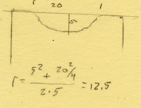
    Transferring the new contour to paper and applying the Chord Equation got the radius of the not-quite circle:

    CatEye magnet crank adapter - chord radius
    CatEye magnet crank adapter – chord radius

    Knowing the size of the magnet and the radius of the circle, drawing the profile in LightBurn was straightforward:

    CatEye magnet crank adapter - framed
    CatEye magnet crank adapter – framed

    Applying the laser cutter to MDF produced the two successive test-fit pieces in the picture while figuring out how much stickout the magnet needed beyond the inner crank face to reach the sensor. LightBurn’s Node Editor simplified adjusting the size: drag-select a group of nodes, then move them in precise increments with the arrow keys.

    Export the profile from LightBurn as an SVG file, import it into OpenSCAD, and extrude it to the proper length:

    module CatEyeMagnet() {
    
    Magnet = [19.0,14.0,8.5];
    
    translate([0,75,0])
        linear_extrude(height=Magnet.y)
            import("CatEye magnet crank adapter.svg");
    
    }
    

    The translate puts the profile approximately at the XY origin. The center = true option moves the profile elsewhere on the XY plane, but does not center it, which may have something to do with the viewport used by LightBurn, the OpenSCAD version I’m using, or something else entirely.

    In any event, the 3D printed mount fits the crank and puts the magnet where it will do the most good:

    CatEye Magnet holder - ProWheel crank - installed
    CatEye Magnet holder – ProWheel crank – installed

    What looks like an obvious curvature mismatch comes from having the tape edge not quite squashed against the crank.

    I should poke a channel through it for a cable tie around the crank, but that 3M foam tape is really good stuff and hasn’t failed me yet.

  • Tailor’s Clapper: 3D Printed Finger Grips

    Tailor’s Clapper: 3D Printed Finger Grips

    With the pockets milled into the oak blocks, the next step is to insert a pair of comfy 3D printed finger grips:

    Ironing weight - prototype grip
    Ironing weight – prototype grip

    Getting comfy required a bank shot off the familiar chord equation to find the radius of a much larger circle producing the proper depth between the known width. The recess then comes from subtracting a hotdog from a lozenge exactly filling the wood pocket.

    Ironing Weight Finger Grip - recess chord
    Ironing Weight Finger Grip – recess chord

    A pair of grips takes just under two hours to print while requiring no attention, which I vastly prefer to tending the Sherline.

    The wood pocket is 7 mm deep and the grips stand 6.5 mm tall, leaving just enough room for three blobs of acrylic adhesive to hold them together. After squishing the grips into their pockets, a pair of right angles aligned everything while the adhesive cured:

    Ironing weight - grip adhesive curing
    Ironing weight – grip adhesive curing

    Mary asked for a longer weight for a place mat project, with a slightly narrower block to compensate for the additional length:

    Ironing weight - seam ironing B
    Ironing weight – seam ironing B

    The grip and pocket were the same size, so it was just a matter of tweaking the block size and cutting more wood.

    All in all, a quick project with satisfying results!

    The OpenSCAD source code as a GitHub Gist:

    // Oak ironing weight finger grips
    // Ed Nisley KE4ZNU 2023-01
    Layout = "Show"; // [Block,Grip,Show,Build]
    //- Extrusion parameters must match reality!
    /* [Hidden] */
    ThreadThick = 0.25;
    ThreadWidth = 0.40;
    HoleWindage = 0.2;
    Protrusion = 0.1; // make holes end cleanly
    inch = 25.4;
    function IntegerMultiple(Size,Unit) = Unit * ceil(Size / Unit);
    ID = 0;
    OD = 1;
    LENGTH = 2;
    //———-
    // Dimensions
    // Length along X axis
    Block = [250.0,50.0,39.0]; // overall wood block
    BlockRadius = 10.0;
    CornerRadius = 10.0;
    Kerf = 0.2;
    Socket = [160.0,25.0,6.5]; // raw recess into block
    SocketRadius = Socket.y/2;
    echo(Socket=Socket,SocketRadius=SocketRadius);
    WallThick = ThreadWidth; // Thinnest printed wall
    Clearance = 0.5; // between grip and recess
    GripBlock = Socket – [2*Clearance,2*Clearance,Clearance];
    GripBlockRadius = SocketRadius – Clearance;
    echo(GripBlock=GripBlock);
    GripDepth = 5.0; // finger grip recess
    GripRecess = [GripBlock.x – 2*WallThick,GripBlock.y – 2*WallThick,GripDepth];
    GripRecessRadius = GripBlockRadius – WallThick;
    echo(GripRecess=GripRecess,GripRecessRadius=GripRecessRadius);
    GripChordRadius = (pow(GripDepth,2) + pow(GripRecess.y,2)/4) / (2*GripDepth);
    echo(GripChordRadius=GripChordRadius);
    NumSides = 4*8;
    //———-
    // Shapes
    module WoodBlock() {
    difference() {
    hull()
    for (i=[-1,1], j=[-1,1]) // rounded block
    translate([i*(Block.x/2 – BlockRadius),j*(Block.y/2 – BlockRadius),-Block.z/2])
    cylinder(r=BlockRadius,h=Block.z,$fn=NumSides);
    for (j=[-1,1]) // grip socket
    translate([0,j*(Block.y/2 + Protrusion),0])
    rotate([j*90,0,0])
    hull() {
    for (i=[-1,1])
    translate([i*(Socket.x/2 – SocketRadius),(Socket.y/2 – SocketRadius),0])
    cylinder(r=SocketRadius,h=Socket.z + Protrusion,$fn=NumSides);
    }
    cube([2*Block.x,2*Block.y,Kerf],center=true);
    }
    }
    module Grip() {
    difference() {
    hull()
    for (i=[-1,1]) // overall grip block
    translate([i*(GripBlock.x/2 – GripBlockRadius),0,0])
    cylinder(r=GripBlockRadius,h=GripBlock.z,$fn=NumSides);
    hull() {
    for (i=[-1,1]) // grip recess
    translate([i*(GripBlock.x/2 – GripRecessRadius – WallThick),
    0,
    GripChordRadius + GripBlock.z – GripDepth])
    sphere(r=GripChordRadius,$fn=NumSides);
    }
    }
    }
    //———-
    // Build them
    if (Layout == "Block")
    WoodBlock();
    if (Layout == "Grip")
    Grip();
    if (Layout == "Show") {
    color("Brown")
    WoodBlock();
    color("Silver")
    for (j=[-1,1])
    translate([0,j*(Block.y/2 – GripBlock.z),0])
    rotate([j*-90,0,0])
    Grip();
    }
    if (Layout == "Build") {
    for (i=[-1,1])
    translate([i*(Block.y/2 – GripBlock.z),0,0])
    rotate([0,0,90])
    Grip();
    }

  • Ironing Weight, a.k.a. Tailor’s Clapper: Overview

    Ironing Weight, a.k.a. Tailor’s Clapper: Overview

    Mary wanted some ironing weights, formally known as tailor’s clappers, to produce flatter seams as she pieced fabric together:

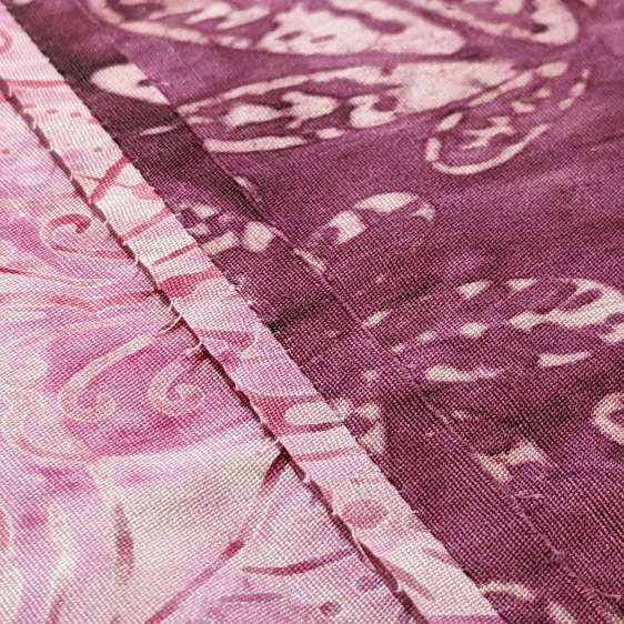
    Ironing weight - flattened seam
    Ironing weight – flattened seam

    The weights are blocks of dense, hard, unfinished wood:

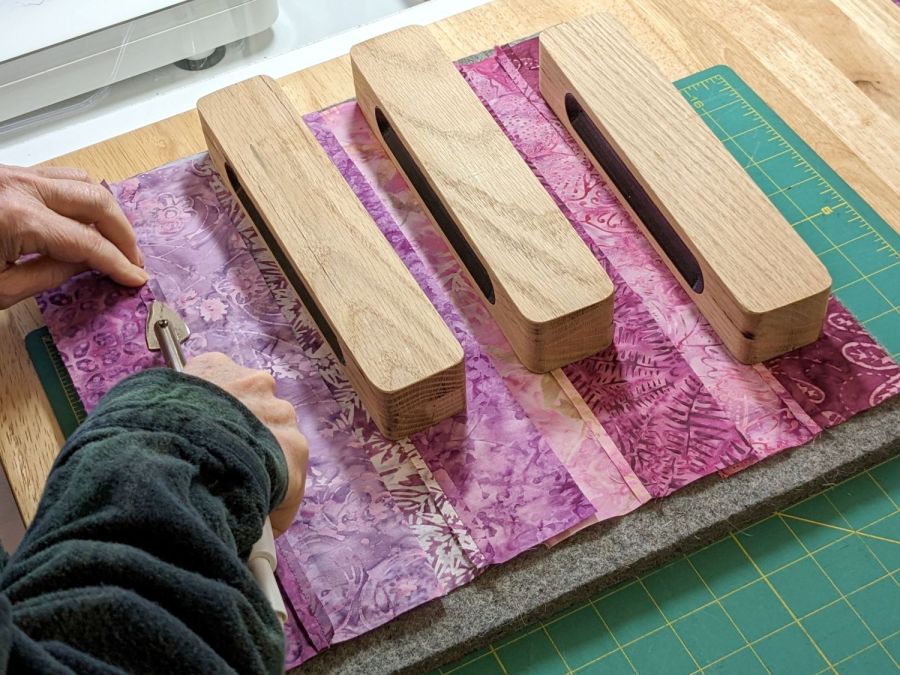
    Ironing weight - seam ironing A
    Ironing weight – seam ironing A

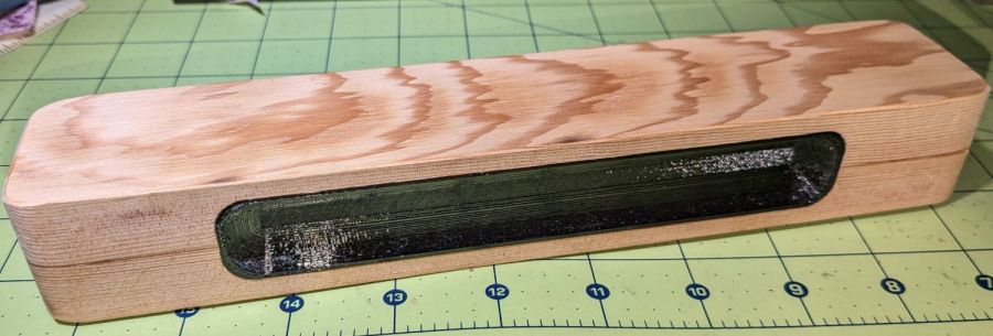
    One can buy commercial versions ranging from cheap Amazon blocks to exotic handmade creations, but a comfortable grip on a block sized to Mary’s hands were important. My lack of woodworking equipment constrained the project, but the picture shows what we settled on.

    The general idea is a rounded wood block with 3D printed grips:

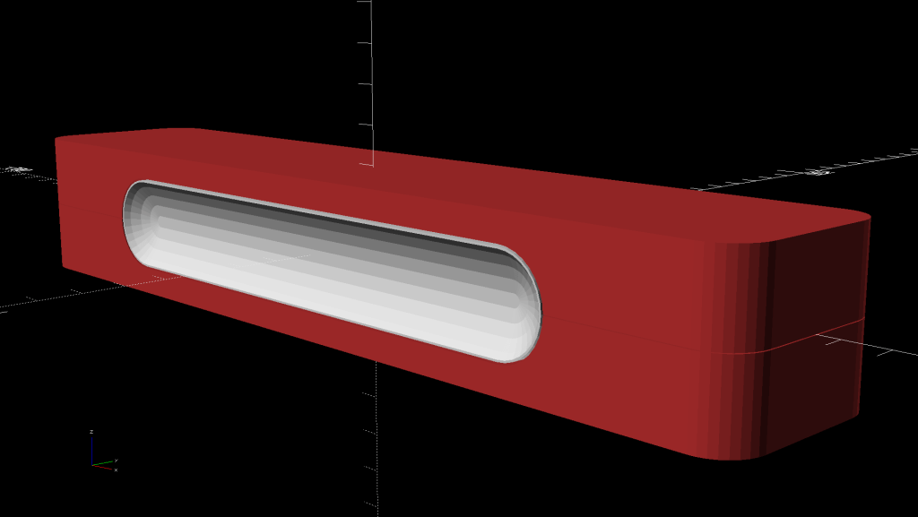
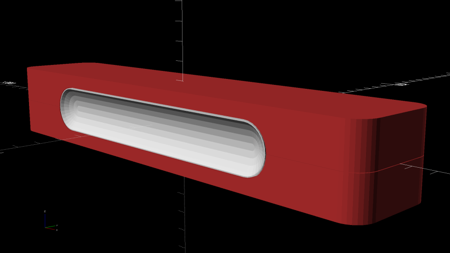
    Ironing Weight Finger Grip
    Ironing Weight Finger Grip

    All other clappers seem to have a simple slot routed along the long sides, presumably using a round-end or ball cutter, which means the cutter determines the shape. This being the age of rapid prototyping, I decided to put the complex geometry in an easy-to-make printed part inserted into a simple CNC-milled pocket.

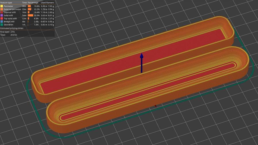
    The first pass at the grip models:

    Ironing Weight Finger Grip - slicer preview
    Ironing Weight Finger Grip – slicer preview

    Both recesses came from spheres sunk to their equators with their XY radii scaled appropriately, then hulled into the final shape. Customer feedback quickly reported uncomfortably abrupt edges along the top and bottom:

    Ironing Weight - maple prototype
    Ironing Weight – maple prototype

    We also decided the straight-end design didn’t really matter, so all subsequent grips have rounded ends to simplify milling the pocket into the block.

    With the goal in mind, the next few posts will describe the various pieces required to make a nice tailor’s clapper customized to fit the user’s hand.

  • Step2 Garden Seat: Seat3

    Step2 Garden Seat: Seat3

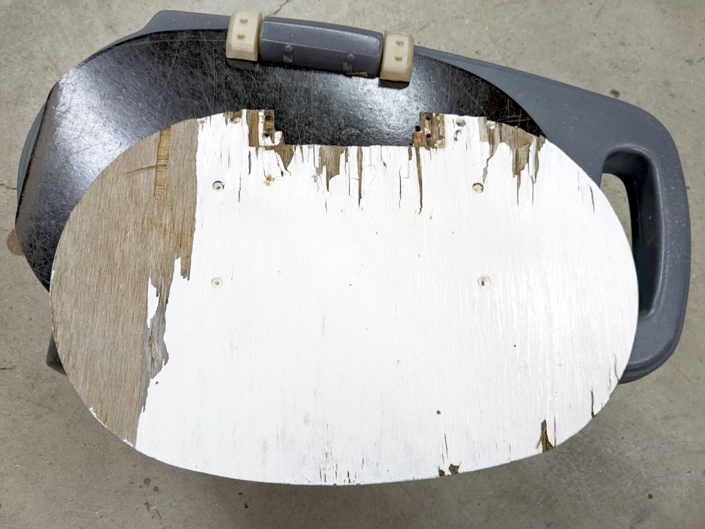
    Another tray becomes a replacement for the plywood on the Step2 rolling seat in the Vassar Farms plot:

    Step2 Garden Seat - weathered plywood
    Step2 Garden Seat – weathered plywood

    I reused the old hinges, as this tray seems to be slightly thicker than the one on the home garden seat. The straight edges show it’s also somewhat smaller, but it’ll work just fine.

    The bottom of the tray with its Silite logo now faces upward, because the top surface has eroded to a matte finish while supporting a bunch of plants outdoors during several summers:

    Step2 Garden Seat - tray top
    Step2 Garden Seat – tray top

    So you can get two or three years from a painted plywood slab out in a garden, depending on how fussy you are about looks.

    After two seasons, the first tray doesn’t look any the worse for wear: Silite trays really will survive the Apocalypse and be ready to serve breakfast the next day.

  • Dripworks Mainline Puncture: In A Good Cause

    Dripworks Mainline Puncture: In A Good Cause

    Mary poked a garden fork tine into the mainline pipe of the garden irrigation plumbIng:

    Mainline pipe puncture
    Mainline pipe puncture

    Fortunately, I have a pipe clamp for just such occasions:

    Mainline pipe puncture - repaired - with cause
    Mainline pipe puncture – repaired – with cause

    After installing the clamp, we excavated the reddish lump just beyond it:

    Mainline pipe puncture - excavated sweet potato
    Mainline pipe puncture – excavated sweet potato

    It’s a purple sweet potato, one of several that had escaped from their assigned plot, grown beyond the pipe, and burrowed under the path.

    Her garden is as neat and tidy as a garden can be, but digging in the soil to find the crops isn’t an exact process!

  • Tour Easy: Another Front Fender Bracket

    Tour Easy: Another Front Fender Bracket

    The mudflap on my front fender rides low enough to snag on obstacles and the most recent incident (about which more later) was a doozy, breaking the left strut ferrule and pulling the bracket off its double-sticky foam tape attachment. Fortunately, the repair kit now has plenty of duct tape.

    The replacement printed up and installed just like its predecessors:

    Tour Easy - front fender bracket
    Tour Easy – front fender bracket

    Having the bracket be the weakest link makes perfect sense to me …