Ed Nisley's Blog: Shop notes, electronics, firmware, machinery, 3D printing, laser cuttery, and curiosities. Contents: 100% human thinking, 0% AI slop.
However, all that upward-directed light goes directly into my glare-sensitive eyeballs, so I added shades above the strips:
COB LED Shade – installed
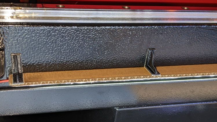
They’re cut from corrugated cardboard because I have an essentially infinite supply and I’m still working out speeds and intensities. Eventually they’ll become something like black acrylic.
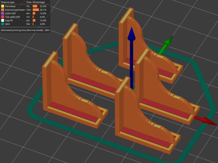
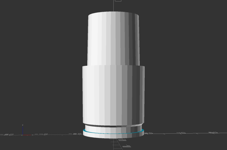
The brackets emerged from the vasty digital deep through the miracle of 3D printing:
COB LED Shade Brackets – slice preview
They’re stuck to the laser cabinet and the cardboard with double-sided duct tape. If you’re careful, they will line up along one edge of the tape, roll over neatly to stick their other face, then a single razor knife cut can separate each pair of neighbors.
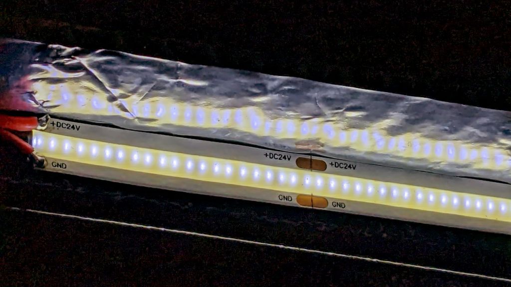
The underside sports an aluminized mylar strip to redirect the wasted light in a more useful direction:
COB LED Shade – aluminized Mylar reflector
The tapeless sticky shipped with the laser holds the reflector in place, while its 20 mm width sets the 21 mm shade dimension. Although you want a reasonably smooth layer, it need not be mirror-flat.
Now it’s really bright in there:
COB LED Shade – overview
While I had my head under the hood, I stuck a fourth strip of COB LEDs on the lip along the rear edge of the opening; it’s bright enough to cast the shadow just forward of the laser head despite the OEM under-gantry LED strip. Because the rear strip is aimed downward, it didn’t need a shade.
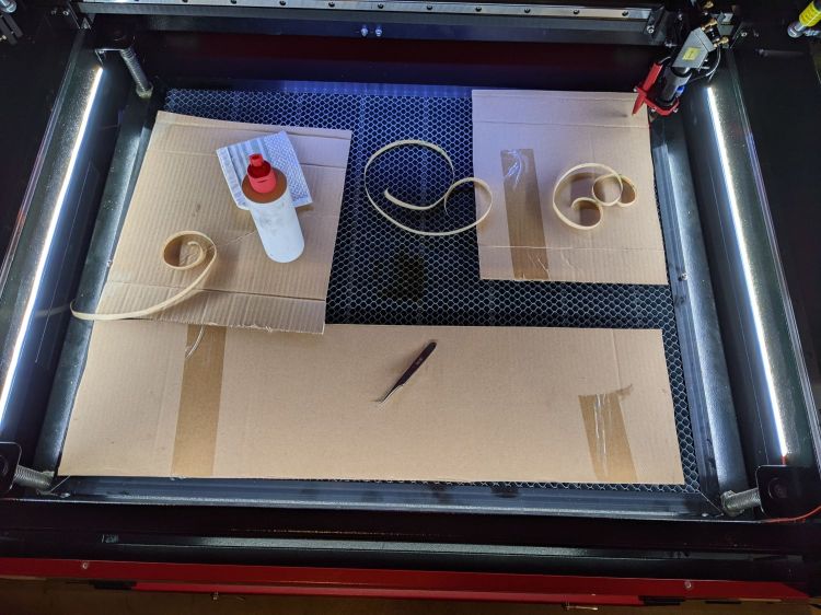
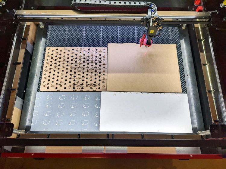
The perforated cardboard sheet on the left is a spike plate: more about that later.
This file contains hidden or bidirectional Unicode text that may be interpreted or compiled differently than what appears below. To review, open the file in an editor that reveals hidden Unicode characters.
Learn more about bidirectional Unicode characters
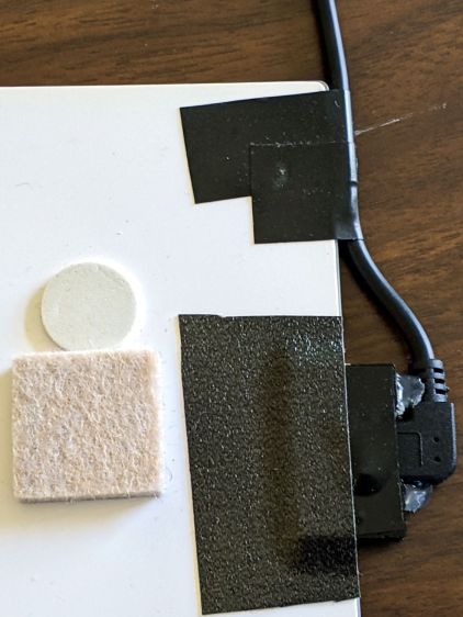
What used to be a “light box” had become a “light pad” powered through a USB Micro-B connector on the side. Unfortunately, the pad’s 5 mm thickness allows for very little mechanical reinforcement around the USB jack, while providing infinite opportunity to apply bending force. Over the course of the last half-dozen years (during which the price has dropped dramatically, despite recent events), the slightest motion flickered the LEDs.
So I squished the jack’s metal shell back into shape, found a short right-angle USB cable, and conjured a reinforcing fixture from the vasty digital deep:
LitUp LED Light Pad
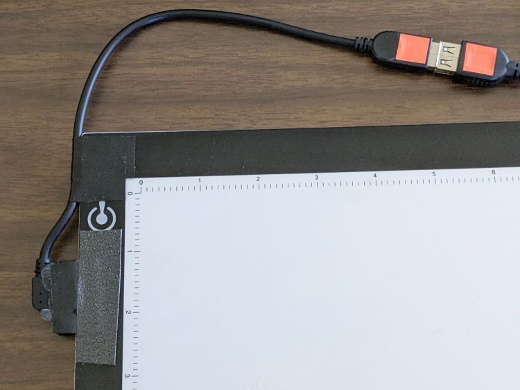
The plate fits under the light pad, where a strip of super-sticky duct tape holds it in place:
LitUp Light Pad USB jack reinforcement – bottom
The USB plug fits between the two blocks with hot-melt glue holding it in place and filling the gap between the plug and the pad.
I’d like to say it’s more elegant than the cable redirection for my tablet, but anything involving black electrical tape and hot-melt glue just isn’t in the running for elegant:
LitUp Light Pad USB jack reinforcement – top
On the other paw, that socket ought to last pretty nearly forever, which counts for a whole lot more around here.
The retina-burn orange tape patches on the connector eliminate all the fumbling inherent to an asymmetric connector with invisible surface features. The USB wall wart on the other end of the cable sports similar markings.
This file contains hidden or bidirectional Unicode text that may be interpreted or compiled differently than what appears below. To review, open the file in an editor that reveals hidden Unicode characters.
Learn more about bidirectional Unicode characters
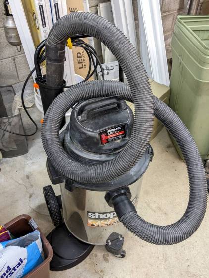
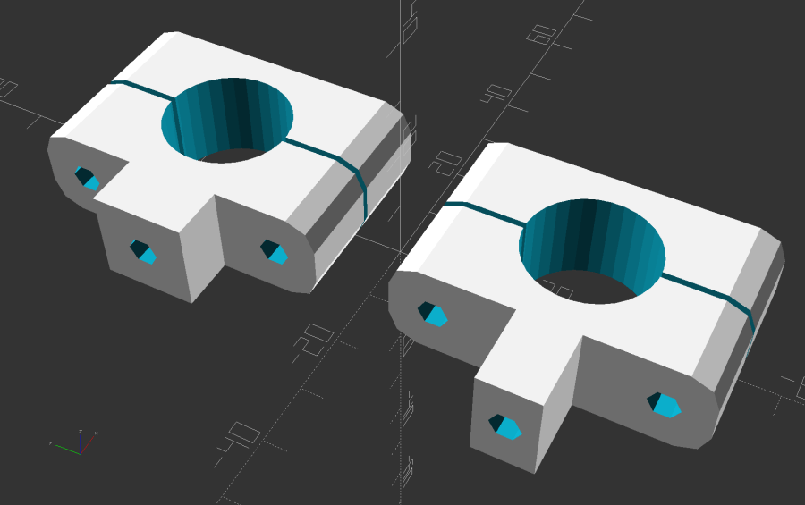
Shortly after acquiring the Greatest ShopVac, I zip-tied half a foot of cardboard tube to the handle to corral the nozzle and keep the ungainly hose from sprawling across the floor. While disembowling the Ottlite into a mini-lathe light, the plastic trim joining the baseplate to the vertical tube cried out to become a nozzle caddy:
ShopVac Nozzle Caddy – front view
It was exactly the right size and shape (by my admittedly slack standards) to hold the nozzle, plus being destined for the trash, so all it needed was a pair of clamp brackets conjured from the vasty digital deep:
ShopVac Nozzle Caddy – solid model
The bosses fit into a tapered slot along what was the rear side, with a pair of 4 mm holes at each end for screws into threaded brass inserts epoxied into the brackets:
ShopVac Nozzle Caddy – clamps mounted
They obviously descend from the many clamp mounts I’ve made for everything from garden hoses to bike running lights. A pair of 4 mm SHCS squish the clamp around the handle, with a strip of electrical tape improving plastic-to-metal griptivity:
ShopVac Nozzle Caddy – side view
The clearance just barely allows a nylock nut atop a washer and you’ll want to trim those 40 mm screws to an exact fit, but it came out pretty well.
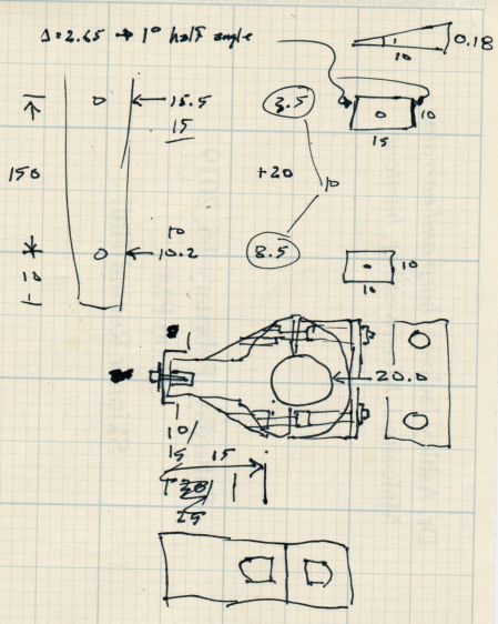
The original dimension doodle with some modeling ideas that didn’t survive more thinking:
ShopVac Nozzle Caddy – Dimension Doodle 1
A more detailed doodle with brass inserts instead of the nylock nuts and an aluminum spreader plate that was obviously not necessary:
ShopVac Nozzle Caddy – Dimension Doodle 2
In retrospect, the inserts would make more sense.
The angle doodles convinced me not to bother modeling either the slot’s taper along its length or its mold draft.
Kinda looks like it grew there and makes one wonder why they don’t include a caddy as a standard option.
This file contains hidden or bidirectional Unicode text that may be interpreted or compiled differently than what appears below. To review, open the file in an editor that reveals hidden Unicode characters.
Learn more about bidirectional Unicode characters
A few months of inactivity left the CNC-3018XL table parked in its homed position where the gentle-but-inexorable pressure of the switch lever displaced the foam holding the plastic actuator tab on the X-axis bearing enough that it would no longer operate reliably:
3018 CNC – Y axis endstop
Putting foam tape in a highly leveraged position produces the same poor results as in finance.
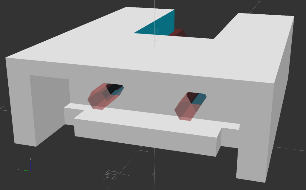
The fix requires reorienting the switch so a solid block on the bearing can push directly on the actuator lever:
CNC-3018 X Home Switch – bottom view
The block must curve around the bearing to give the tape enough surface area for a good grip:
CNC-3018 X Home Switch – oblique view
The solid model for the new X-axis mount looks about like you’d expect:
CNC-3018 X Home Switch Mount – solid model
I increased the home switch pulloff to 2 mm, although it’s not clear that will make any difference in the current orientation.
This file contains hidden or bidirectional Unicode text that may be interpreted or compiled differently than what appears below. To review, open the file in an editor that reveals hidden Unicode characters.
Learn more about bidirectional Unicode characters
The top pair of screw heads aren’t quite flush with the cover, so the knobs have 1 mm extensions:
Micromark Bandsaw – cover screw knobs – upper
The bottom pair sit inside 4 mm recesses, so those knobs get matching extensions:
Micromark Bandsaw – cover screw knobs – lower
Attacking an anonymous 5 mm hex wrench with a Dremel cutoff wheel produced a quartet of 12 mm shafts and reduced drawer clutter by one unit.
In retrospect, I should have dismantled the cover, grabbed the screws in a vise with their shafts vertical, and epoxied all the knobs with perfect alignment. Next time, maybe.
A lithium battery management system can (and should!) disable the battery output to prevent damage from overcurrent or undervoltage, after which it must be reset. The inadvertent charge port short may have damaged the BMS PCB, but did not shut down the battery’s motor output, which means the BMS will not should not require resetting. However, because all this will happen remotely, it pays to be prepared.
For this battery, the positive terminal is on the right, as shown by the molded legend and verified by measurement.
A doodle with various dimensions, most of which are pretty close:
Bafang battery – connector dimension doodle
Further doodling produced a BMS reset adapter keyed to fit the battery connector in only one way:
Bafang battery – adapter doodle
Which turned into the rectangular lump at the top of the tool kit, along with the various shell drills and suchlike discussed earlier:
Bafang battery tools
Looking into the solid model from the battery connector shows the notches and projections that prevent it from making incorrect contact:
Battery Reset Adapter – show front
The pin dimensions on the right, along with a mysterious doodle that must have meant something at the time :
Bafang battery – adapter pin doodle
The pins emerged from 3/16 inch brass rod, with pockets for the soldered wires:
Bafang battery – reset tool – pins
The wires go into a coaxial breakout connector that’s hot-melt glued into the recess. The coaxial connectors are rated for 12 V and intended for CCTV cameras, LED strings, and suchlike, but I think they’re good for momentary use at 48 V with minimal current.
I printed the block with the battery connector end on top for the best dimensional accuracy and the other end of the pin holes held in place by a single layer of filament bridging the rectangular opening:
Bafang battery – reset tool – hole support layer
I made a hollow punch to cut the bridge filaments:
Bafang battery – reset tool – pin hole punch
The holes extend along the rectangular cutout for the coaxial connector, so pressing the punch against the notch lines it up neatly with the hole:
Bafang battery – reset tool – hole punching
Whereupon a sharp rap with a hammer clears the hole:
Bafang battery – reset tool – hole cleared
A dollop of urethane adhesive followed the pins into their holes to lock them in place. I plugged the block and pins into the battery to align the pins as the adhesive cured, with the wire ends carefully taped apart.
After curing: unplug the adapter, screw wires into coaxial connector, slobber hot melt glue into the recess, squish into place, align, dribble more glue into all the gaps and over the screw terminals, then declare victory.
It may never be needed, but that’s fine with me.
[Update: A few more doodles with better dimensions and fewer malfeatures appeared from the back of the bench.]
This file contains hidden or bidirectional Unicode text that may be interpreted or compiled differently than what appears below. To review, open the file in an editor that reveals hidden Unicode characters.
Learn more about bidirectional Unicode characters
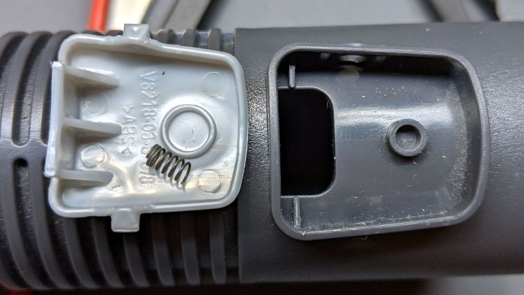
The adapter rotated freely inside the socket, so its diameter was correct and it wasn’t jammed, but pushing the latch button (at the depression on the right) didn’t release the adapter.
Popping the latch out of the tube let the adapter slide easily out of the socket and exposed the innards:
Dirt Devil Floor Tube – latch internals
The two bosses inside the latch originally captured a nice conical spring:
Dirt Devil Floor Tube – conical latch spring
The tab on the left side of the latch button engages a slot in the OEM brush head and the recessed ring around my adapters:
Dirt Devil Nozzle Bushing – solid model
It turns out the molded tab was slightly too long, so pushing the latch button all the way down didn’t retract the tab out of the bore, so it remained engaged in the adapter’s ring.
The conical spring also didn’t seem to collapse completely flat, so the bosses inside the latch button couldn’t quite bottom out, leaving the tab protruding even further inside the bore. It also required an inordinate amount of force to push the latch all the way down.
While fiddling with all this, I noticed that the OEM floor brush would sometimes hang up on the tab, so the operation wasn’t all that smooth even with the original equipment.
So I trimmed maybe half a millimeter off the tab, just enough to release the adapter with the button fully pressed and without the conical spring, then replaced the conical spring with a tiny spring (from the Big Box o’ Random Springs) trimmed to allow the full range of travel. This not only released the adapter, it also let the OEM floor brush pop out more easily.
A zero-dollar repair, although with considerable annoyance.


