Ed Nisley's Blog: Shop notes, electronics, firmware, machinery, 3D printing, laser cuttery, and curiosities. Contents: 100% human thinking, 0% AI slop.
Chain Mail – PETG on nozzle – platform switch clearance
The clearance under that switch lever doesn’t amount to much…
The patch came out looking pretty good, though:
Chain Mail – 4-wide – PETG hairs – bridging
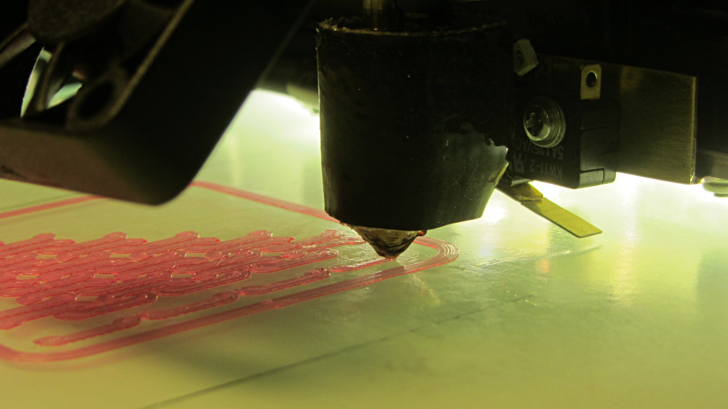
The small red blob on the right side of the nozzle in the first picture tells a tale: the nozzle tends to pull fine hairs from one perimeter to the next, despite 1 mm of retraction. Fiddling with the retraction on subsequent patches didn’t improve matters.
Even though the infill isn’t overstuffed, the nozzle tends to collect and redeposit small amounts of PETG as it travels over the surface. Those small blobs turn into fine hairs when the nozzle moves from one island to the next.
Reducing the bars from six threads to four threads shows that bridging (at 25 mm/s and 0.9 flow rate) seems messier than PLA:
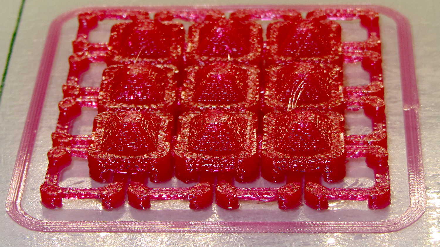
Chain mail – 4 strand PETG bridging
Despite that, all the links came out OK and the sheet was reasonably flexible. After some fiddling with speeds and patterns, these small-link patches popped off the platform easily and were just as flexy as the PLA sheet below them:
Changing from PLA to PETG with a V4 hot end and 24 V power required several slicing adjustments, some of which weren’t at all obvious. It’s not all settled down, but what you see here comes from a bunch of test objects and tweaks that you’ll see over the next few days; this is basically a peek into the future.
M2 V4 Calibration Objects
The obvious changes:
Extrusion temperature: 250 °C
Platform temperature: 90 °C
Hot PETG seems rather sticky and produces hair-fine strings that aren’t due to poor retraction. Running at 230 °C is possible, but the strings are nasty. The V4 hot end shouldn’t run over 250 °C; fortunately, some tests suggest the stringing doesn’t Go Away at 260 °C, so moah powah! isn’t required.
Hair spray on glass works well above 90 °C and not at all below 80 °C. A stick of Elmer’s Washable Glue Stick, chosen because it was on the Adhesive Shelf, produced exactly zero adhesion at any platform temperature I was willing to use. Its “washable” nature surely contributed to the failure; you want something that’s gonna stick with you forever.
The eSun PETG filament diameter varies from 1.63 to 1.72 mm, which seems like a lot compared to the MakerGear PLA I’d been using; I’ve told Slic3r to run with 1.70 mm. In practice, it doesn’t seem to matter; the average over a meter works out to 1.70, I haven’t seen any abrupt bulges, and the objects come out fine. This spool arrived late last year, early in eSun’s production, so perhaps they’ve smoothed things out by now.
A few iterations of thinwall box building put the Extrusion Multiplier at 1.11, producing a spot-on 0.40 mm thread width at either 0.20 or 0.25 mm thread thickness.
Infill:
Infill overlap: 10%
Max infill: 40%
Infill pattern: 3D Honycomb
Top/bottom pattern: Hilbert Curve
Combine infill: 3 layers
The first attempt at a solid box (left of center, first row) became so overstuffed I canceled the print; the top bulges upward. A few parameter tweak iterations produced the perfect 100% filled solid box to its right, but in actual practice a 40% 3D Honeycomb will be entirely strong enough for anything I build.
Reducing the overlap from 15% to 10% reduced the obviously overstuffed junction just inside the perimeter threads.
Cooling:
Fan for layers below 20 s
Minimum layer time: 10 s
Minimum speed: 10 mm/s
PETG wants to go down hot, but printing a single thinwall box requires that much cooling to prevent slumping. Might be excessive; we shall see.
Speeds:
First layer: 15 mm/s
External perimeters: 25 mm/s
Perimeters: 50 mm/s
Infill: 75 mm/s
Travel: 300 mm/s
Slower XY speeds seem to produce better results, although those values aren’t based on extensive experience.
The first layer doesn’t work well at higher speeds, with acute corners and edges pulling up as the nozzle moves away. Using the Hilbert Curve pattern not only looks pretty, but also ensures the nozzle spends plenty of time in the same general area. Higher platform temperatures work better, too, and I may goose the 40 V supply a bit to improve the 0.2 °C/s warmup rate.
The travel speed went up from 250 mm/s in an attempt to reduce stringing, but it may be too aggressive for the Y axis with the new 24 V supply. On very rare occasions, the Y axis stalls during homing, despite not changing the speeds in the startup G-Code, and I’m still accumulating experience with that.
Bridging isn’t nearly as clean as PLA. After some tinkering, a bridge speed of 25 mm/s and flow of 0.90 seems to work, but some chain mail patches suggest there’s plenty of room for improvement.
Mechanically, PETG is softer and more resilient than PLA, with a much higher glass transition temperature. Larger objects with 40% infill are essentially rigid and smaller objects are bendy, rather than brittle.
On the whole, PETG seems like it will work well for the stuff I build, although magenta isn’t my favorite color…
CAUTION: Don’t use this Slic3r configuration unless:
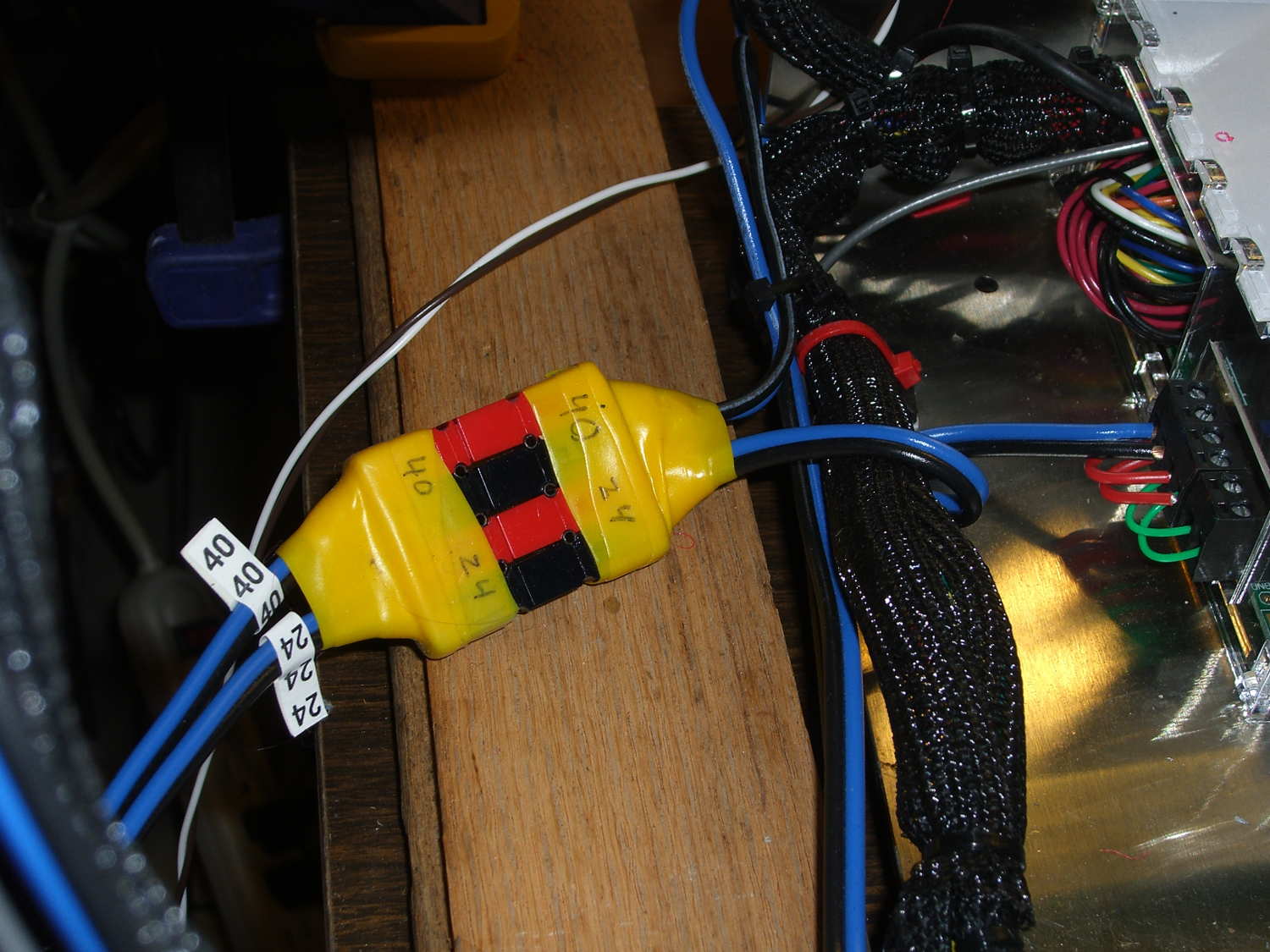
Now, with the V4 hot end and fans installed, I popped a 24 V supply brick off the heap and connected another set of Powerpoles:
M2 – Powerpole connector block
The 24 V supply now powers everything on the RAMBo board, with the platform heater running from the 40 V supply through the DC-DC solid state relay.
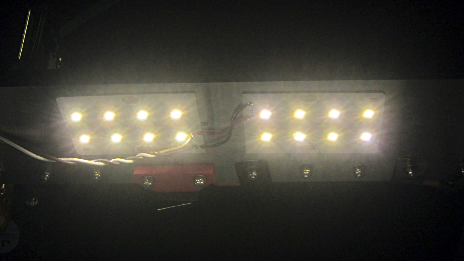
Unfortunately, wiring the LED panels to the RAMBo MOSFET driving the fans didn’t quite work. Turns out that the extruder PWM pulses produce corresponding LED blinks; the V4 hot end draws 1.5 A and that’s enough to flicker the lights. So they’re back on the wall wart and glow steadily again.
For whatever it’s worth, the panels don’t have limiting resistors, just eight 150 mA LED emitters in series…
Given that I’m throwing all the balls in the air at once:
V4 hot end / filament drive
24 VDC motor / logic power supply
PETG filament
It seemed reasonable to start with the current Marlin firmware, rather than the MakerGear version from long ago. After all, when you file a bug report, the first question is whether it happens with the Latest Version.
Marlin has undergone a Great Refactoring that moved many of the constants around. I suppose I should set up a whole new Github repository, but there aren’t that many changes and I’ve gotten over my enthusiasm for forking projects.
Anyhow, just clone the Marlin repo and dig in.
In Marlin_main.cpp, turn on the Fan 1 output on Arduino pin 6 that drives the fans on the extruder and electronics box:
pinMode(6,OUTPUT);	// kickstart Makergear M2 extruder fan
digitalWrite(6,HIGH);
You could use the built-in extruder fan feature that turns on when the extruder temperature exceeds a specific limit. I may try that after everything else works; as it stands, this shows when the firmware gets up & running after a reset.
In Configuration_adv.h, lengthen the motor-off time and set the motor currents:
I missed the max & min position settings on the first pass (they’re new!), which matter because I put the origin in the middle of the platform, rather than the front-left corner. Marlin now clips coordinates outside that region, so the first thinwall calibration box only had lines in Quadrant 1…
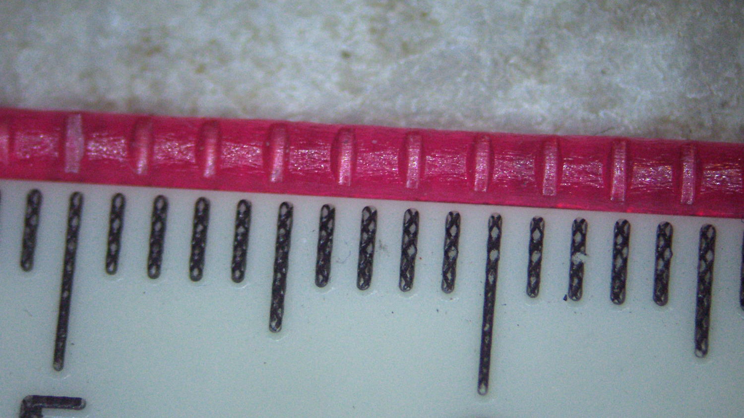
Running some PETG filament through the M2’s new V4 extruder drive produced nice indentations from the drive gear:
PETG filament indentations – front view
The square-looking indentation at the far left came from having the filament sit unmoving for an hour or so. There’s a smaller indentation to the left of that from a partially engaged gear tooth.
The side view:
PETG filament indentations – side view
That’s with the adjusting screw cranked 1/2 turn inward from what felt like first contact.
It’s an M4 screw with 0.7 mm pitch, so each turn moves the extruder pressure arm 0.35 mm. However, the bearing actually pressing the filament against the drive gear is 1/3 of the distance from the fulcrum to the screw:
M2 V4 Filament Drive – front view
Sooooo the bearing should move more-or-less 1/3 as far as the screw, modulo the arm bending, the fulcrum not actually being a pivot, and suchlike: 0.35 mm at the screw should push the gear 0.1 mm into the filament.
Squinting at the filament through a measuring magnifier says the indentations are 0.30 mm deep, which means the screw moved 1.0 mm after the actual “first contact” with the filament. That’s not surprising: PETG filament seems soft and easily indented, the force required to dent the filament doesn’t amount to much, plus there’s plenty of mechanical advantage from my fingers through the screwdriver to the filament.
Turning the screw another half turn certainly won’t mash the drive gear teeth another 0.1 mm into the filament, though, because the force increases dramatically as the dent goes deeper into the filament.
My M2 dates back to early 2013 and arrived with a 12 V platform power brick and a 19 V brick for everything else. I replaced the platform with a hotrod version, used a DC-DC SSR to control the high-current path, drove it from a 48 V brick dialed back to 40 V, and left the 19 V brick alone.
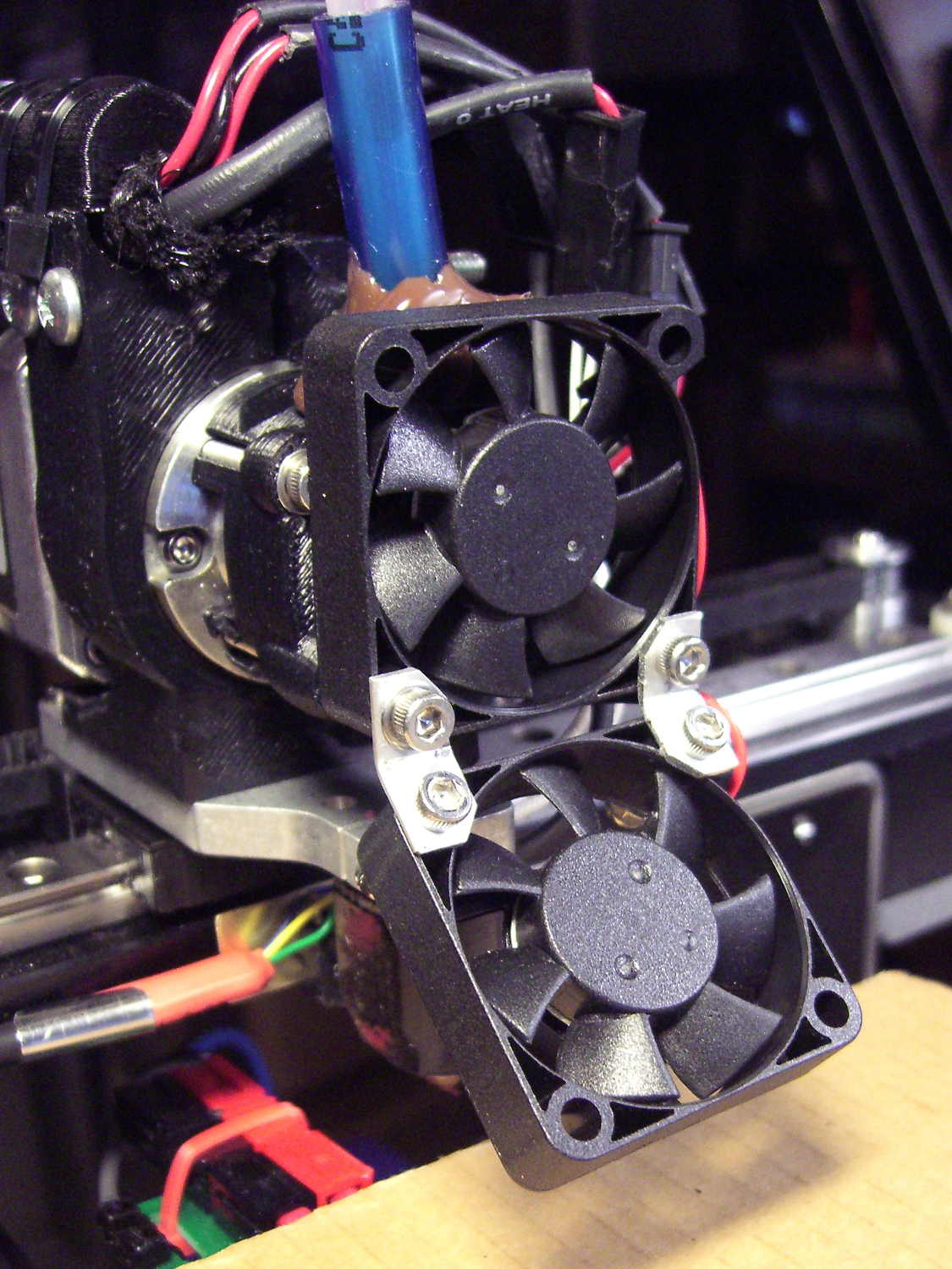
Recent M2s use a single 24 V brick for everything, including the motors and V4 hot end, so I decided to ditch the 19 V supply when I installed the new hot end. The stock 12 V fans depended on PWM to reduce the 19 V supply to something tolerable, but, with 24 V ball bearing fans being cheap & readily available, I replaced all three.
I bashed a pair of angled brackets from a random heatsink fin to hold the extruder & platform fans together:
M2 V4 Extruder – 24 V fans
All of that hangs from the single screw in the lower left corner of the upper fan, which has worked well enough and never given any trouble, despite my misgivings.
They’re much quieter than the original fans, perhaps as a result of operating at their rated voltage without PWM trickery. In theory, the fan mounted horizontally in the electronics box should survive longer with ball bearings, but the original sintered-bearing fan didn’t complain too much.