Ed Nisley's Blog: Shop notes, electronics, firmware, machinery, 3D printing, laser cuttery, and curiosities. Contents: 100% human thinking, 0% AI slop.
My M2 dates back to early 2013 and arrived with a 12 V platform power brick and a 19 V brick for everything else. I replaced the platform with a hotrod version, used a DC-DC SSR to control the high-current path, drove it from a 48 V brick dialed back to 40 V, and left the 19 V brick alone.
Recent M2s use a single 24 V brick for everything, including the motors and V4 hot end, so I decided to ditch the 19 V supply when I installed the new hot end. The stock 12 V fans depended on PWM to reduce the 19 V supply to something tolerable, but, with 24 V ball bearing fans being cheap & readily available, I replaced all three.
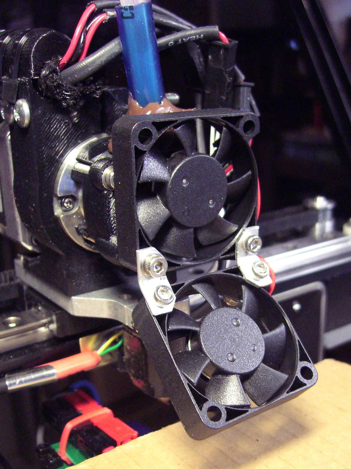
I bashed a pair of angled brackets from a random heatsink fin to hold the extruder & platform fans together:
M2 V4 Extruder – 24 V fans
All of that hangs from the single screw in the lower left corner of the upper fan, which has worked well enough and never given any trouble, despite my misgivings.
They’re much quieter than the original fans, perhaps as a result of operating at their rated voltage without PWM trickery. In theory, the fan mounted horizontally in the electronics box should survive longer with ball bearings, but the original sintered-bearing fan didn’t complain too much.
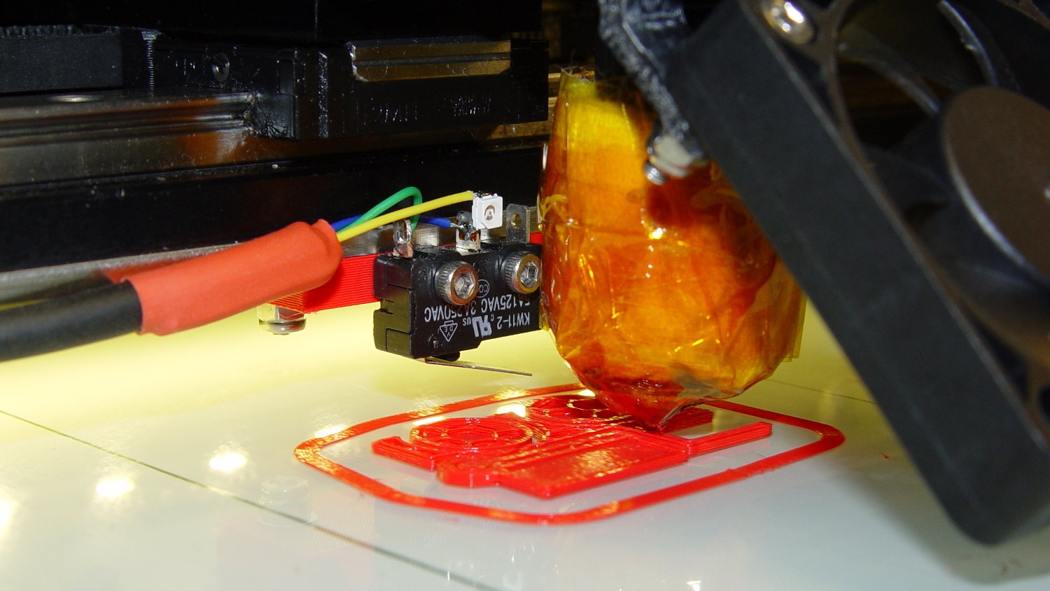
Mounting the Z-axis platform switch on the X gantry to sense the actual platform position worked perfectly with the original MakerGear V3 hot end, at least after I relocated the switch a bit further from the balance point. It does require moving the nozzle off the platform before homing the Z axis, for the obvious reason:
M2 Z-min switch – center gantry – in action
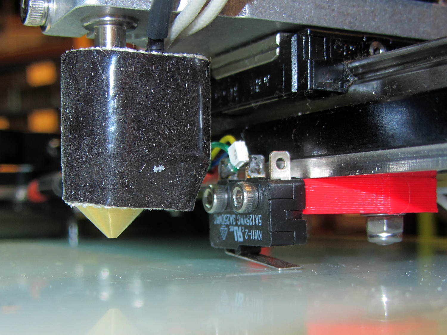
The smaller MakerGear V4 hot end uses a completely different mount that puts the nozzle higher than the switch lever:
M2 V4 hot end vs platform Z switch
The clearances were close enough to rule out plastic, so I bandsawed some 33 mil (1/32 inch) brass shim stock and drilled holes in the appropriate spots:
Brass switch bracket – drilling
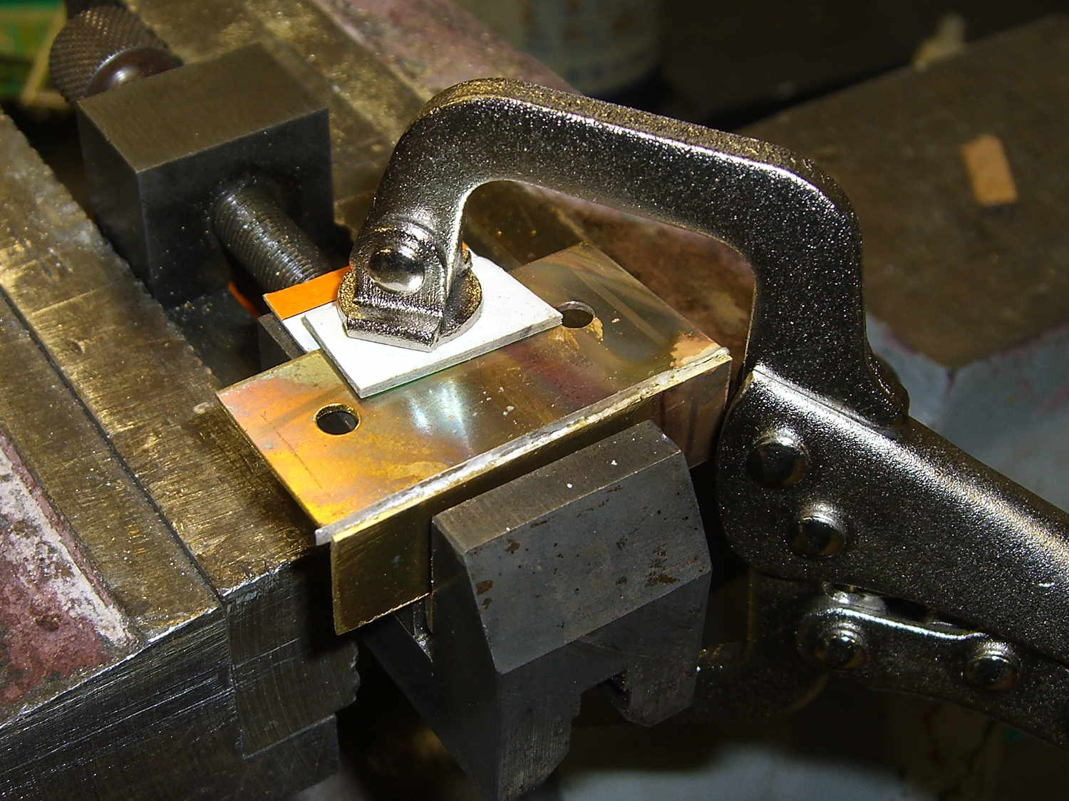
After discovering the blindingly obvious fact that you can’t heat brass sheets clamped to a steel vise enough to melt silver solder, I padded the brass with cardboard insulation and tried again:
Brass switch bracket – clamped for soldering
The cardboard charred and burned and stank up the shop, but held everything in alignment long enough:
Brass switch bracket – soldered
A bit of file & sandpaper work shined it up just fine, then I slotted the lower mounting holes enough to accommodate 2-56 nuts between the gantry and the bracket:
Brass switch bracket – mounted – front view
Yeah, I could tap 2-56 holes into the brass sheet, but let’s be reasonable: two turns does not a secure fitting make.
Here’s why a plastic bracket wouldn’t work:
Brass switch bracket – side view
That’s with the V4 hot end aligned per instructions, although I may rotate it 1/4 turn clockwise at some point. Note that there’s no filament going in the top, as I did all this before firing that devil up for the first time.
The switch lever had enough free travel that the platform would hit the bottom of the X axis linear slide screws before activating the switch, but lowering the switch would put the lever below the nozzle. I added a 15 mil brass shim to the lever and it’s all good:
Brass switch bracket – lever shim detail
Admittedly, the lever rests a bit less than 1.000 mm above the nozzle, but we’ll see how much trouble that causes.
The switch trips 2.0 mm above the nozzle, so the new startup G-Code looks like this:
;-- Slic3r Start G-Code for M2 starts --
;  Ed Nisley KE4NZU - 2015-03-01
;  Makergear V4 hot end
; Z-min switch at platform, must move nozzle to X=135 to clear
M140 S[first_layer_bed_temperature]	; start bed heating
G90				; absolute coordinates
G21				; millimeters
M83				; relative extrusion distance
G92 Z0			; set Z to zero, wherever it might be now
G1 Z10 F1000	; move platform downward to clear nozzle; may crash at bottom
G28 Y0			; home Y to clear plate, origin in middle
G92 Y-127
G28 X0			; home X, origin in middle
G92 X-100
G1 X130 Y0 F30000	; move off platform to right side, center Y
G28 Z0			; home Z to platform switch, with measured offset
G92 Z-2.00
G0 Z2.0			; get air under switch
G0 Y-127 F10000	; set up for priming, zig around corner
G0 X0			;  center X
G0 Y-125.0		; just over platform edge
G0 Z0 F500	; exactly at platform
M109 S[first_layer_temperature]	; set extruder temperature and wait
M190 S[first_layer_bed_temperature]	; wait for bed to finish heating
G1 E20 F300		; prime to get pressure, generate blob on edge
G0 Y-123		; shear off blob
G1 X15 F20000	; jerk away from blob, move over surface
G4 P500			; pause to attach
G1 X45 F500		; slowly smear snot to clear nozzle
G1 Z1.0 F2000	; clear bed for travel
;-- Slic3r Start G-Code ends --
The prime-and-wipe section accommodates gooey PETG, although that will require more attention.
That lets me position the whole affair to the right of the sewing machine, in what seems to be its natural position, without having the cable form a loop that would push it off the platform. It’s not entirely clear how we’ll keep a straight cable from pulling it off, but that’s in the nature of fine tuning.
Anyhow, rotating the LCD isn’t a big deal, because the Adafruit library does all the heavy lifting:
// LCD orientation: always landscape, 1=USB upper left / 3=USB lower right
#define LCDROTATION 3

... snippage ...
tft.begin();
tft.setRotation(LCDROTATION);	// landscape, 1=USB upper left / 3=USB lower right
Flipping the touch screen coordinates required just interchanging the “to” bounds of the map() functions, with a conditional serving as institutional memory in the not-so-unlikely event I must undo this:
#if LCDROTATION == 1
	p->x = map(t.y, TS_Min.y, TS_Max.y, 0, tft.width());	// rotate & scale to TFT boundaries
	p->y = map(t.x, TS_Min.x, TS_Max.x, tft.height(), 0);	//   ... USB port at upper left
#elif LCDROTATION == 3
	p->x = map(t.y, TS_Min.y, TS_Max.y, tft.width(), 0);	// rotate & scale to TFT boundaries
	p->y = map(t.x, TS_Min.x, TS_Max.x, 0, tft.height());	//   ... USB port at lower right
#endif
The solid model shows two screws holding the PCB in place:
Arduino Mega PCB Mount
I decided to edge-clamp the board, rather than fuss with the built-in screws, just because 3D printing makes it so easy.
Of course, the UI needs a real case that will hold it at an angle, so as to make the LCD and touch screen more visible and convenient; this mount just keeps the PCB up off the conductive surface of the insulating board we’re using in lieu of a Real Sewing Platform.
This sewing machine project involves a lot of parts…
The DC-DC boost power supply for the LED needle lights has four mounting holes, two completely blocked by the heatsink and the others against components with no clearance for screw heads, soooo …
3D printing to the rescue:
Boost converter – installed
Now that the hulking ET227 operates in saturation mode, I removed the blower to make room for the power supply. Two strips of double-stick foam tape fasten the holder to the removable tray inside the Dell GX270’s case.
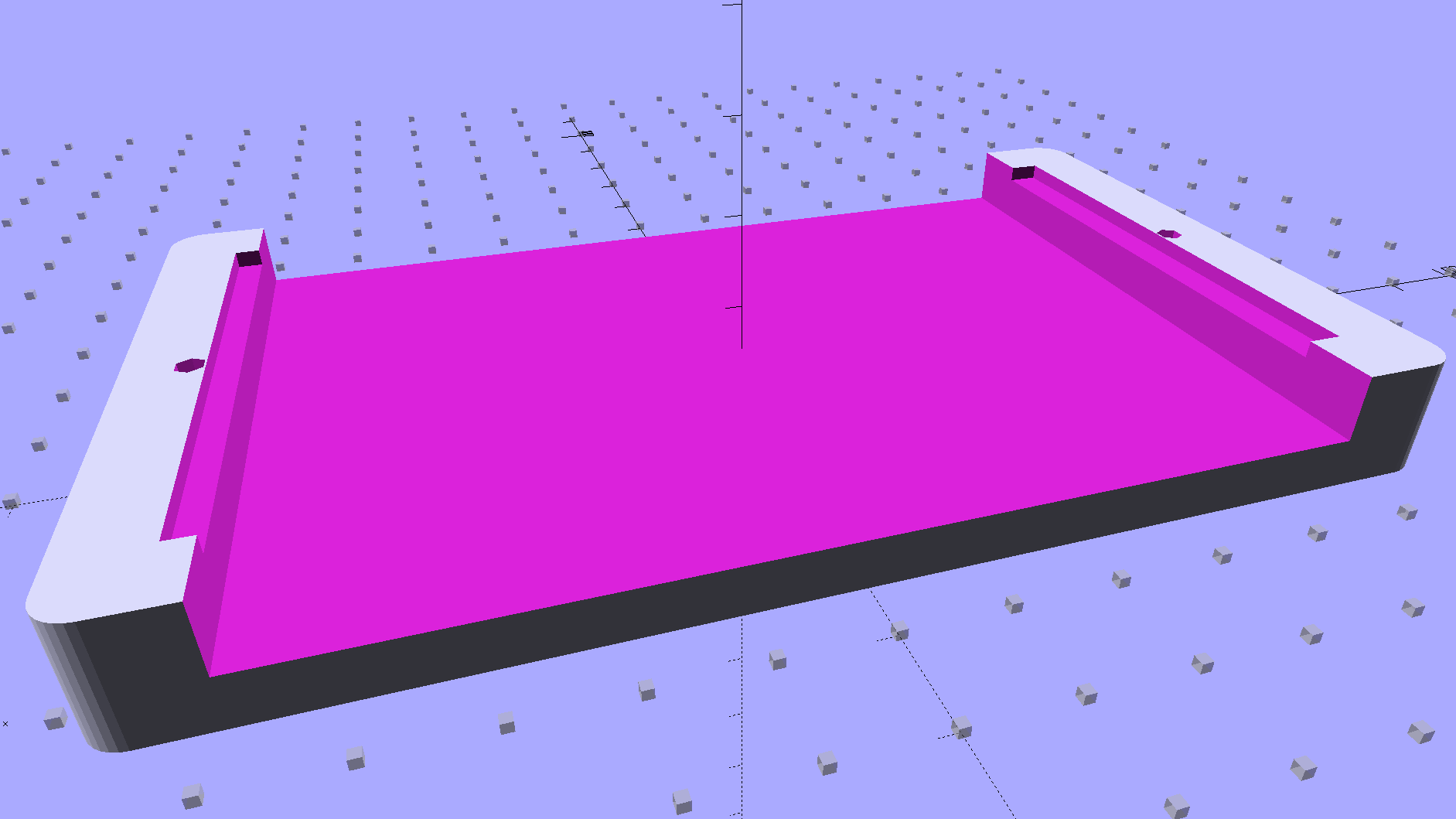
It’s basically a rounded slab with recesses for the PCB and clearance for solder-side components:
Boost converter mount – as printed
The solid model shows the screw holes sitting just about tangent to the PCB recess:
XW029 Booster PCB Mount
That’s using the new OpenSCAD with length scales along each axis; they won’t quite replace my layout grid over the XY plane, but they certainly don’t require as much computation.
I knew my lifetime supply of self-tapping hex head 4-40 screws would come in handy for something:
Boost converter in mount
The program needs to know the PCB dimensions and how much clearance you want for the stuff hanging off the bottom:
PCBoard = [66,35,IntegerMultiple(1.8,ThreadThick)];

BottomParts = [[1.5,-1.0,0,0],	// xyz offset of part envelope
				[60.0,37.0,IntegerMultiple(3.0,ThreadThick)]];	// xyz envelope size (z should be generous)
That’s good enough for my simple needs.
The hole locations form a list-of-vectors that the code iterates through:
That’s the first occasion I’ve had to try iterating a list and It Just Worked; I must break the index habit. The newest OpenSCAD version has Python-ish list comprehensions which ought to come in handy for something.
The “Z coordinate” of each hole position gives its rotation, so I could snuggle them up a bit closer to the edge by forcing the proper polygon orientation. The square roots in the second two holes make them tangent to the corners of the PCB, rather than the sides, which wasn’t true for the first picture. Fortunately, the washer head of those screws turned out to be just big enough to capture the PCB anyway.
Our Larval Engineer volunteered to convert the lens from a defunct magnifying desk lamp into a hand-held magnifier; there’s more to that story than is relevant here. I bulldozed her into making a solid model of the lens before starting on the hand-holdable design, thus providing a Thing to contemplate while working out the holder details.
That justified excavating a spherometer from the heap to determine the radius of curvature for the lens:
Student Sphereometer on lens
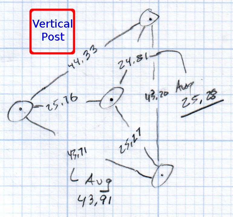
You must know either the average radius / diameter of the pins or the average pin-to-pin distance. We used a quick-and-dirty measurement for the radius, but after things settled down, I used a slightly more rigorous approach. Spotting the pins on carbon paper (!) produced these numbers:
Sphereometer Pin Radii
The vertical scale has hard-metric divisions: 1 mm on the post and 0.01 on the dial. You’d therefore expect the pins to be a hard metric distance apart, but the 25.28 mm average radius suggests a crappy hard-inch layout. It was, of course, a long-ago surplus find without provenance.
The 43.91 mm average pin-to-pin distance works out to a 50.7 mm bolt circle diameter = 25.35 mm radius, which is kinda-sorta close to the 25.28 mm average radius. I suppose averaging the averages would slightly improve things, but …
The vertical distance for the lens in question was 0.90 mm, at least for our purposes. That’s the sagitta, which sounds cool enough to justify this whole exercise right there. It’s 100 mm in diameter and the ground edge is 2.8 mm thick, although the latter is subject to some debate.
Using the BCD, the chord equation applies:
Height m = 0.90 mm
Base c = 50.7 mm
Lens radius r = (m2 + c2/4) / 2m = 357.46 mm
Using the pin-to-pin distance, the spherometer equation applies:
Pin-to-pin a = 43.91 mm
Sagitta h = 0.90 mm
Lens radius R = (h/2) + (a2 / 6h) = 357.50 mm
Close enough, methinks.
Solving the chord equation for the total height of each convex side above the edge:
Base c = 100 mm
Lens radius r = 357.5 mm
Height m = r – sqrt(r2 -c2/4) = 3.5 mm
So the whole lens should be 2 · 3.5 + 2.8 = 9.8 mm thick. It’s actually 10.15 mm, which says they were probably trying for 10.0 mm and I’m measuring the edge thickness wrong.
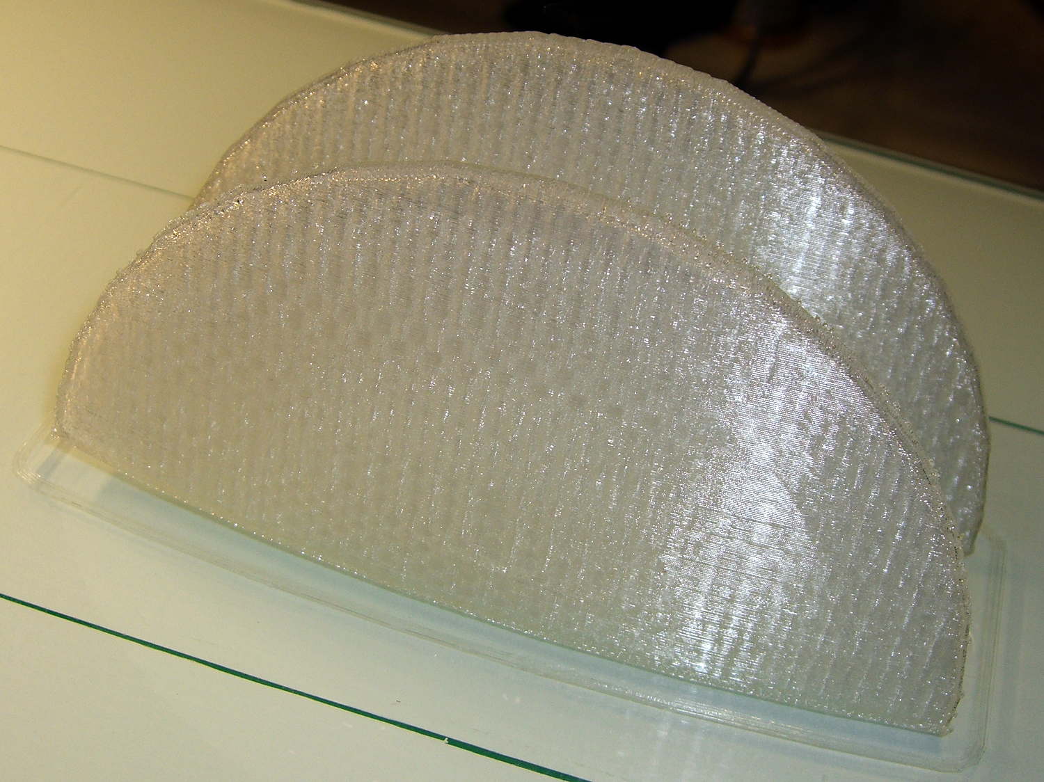
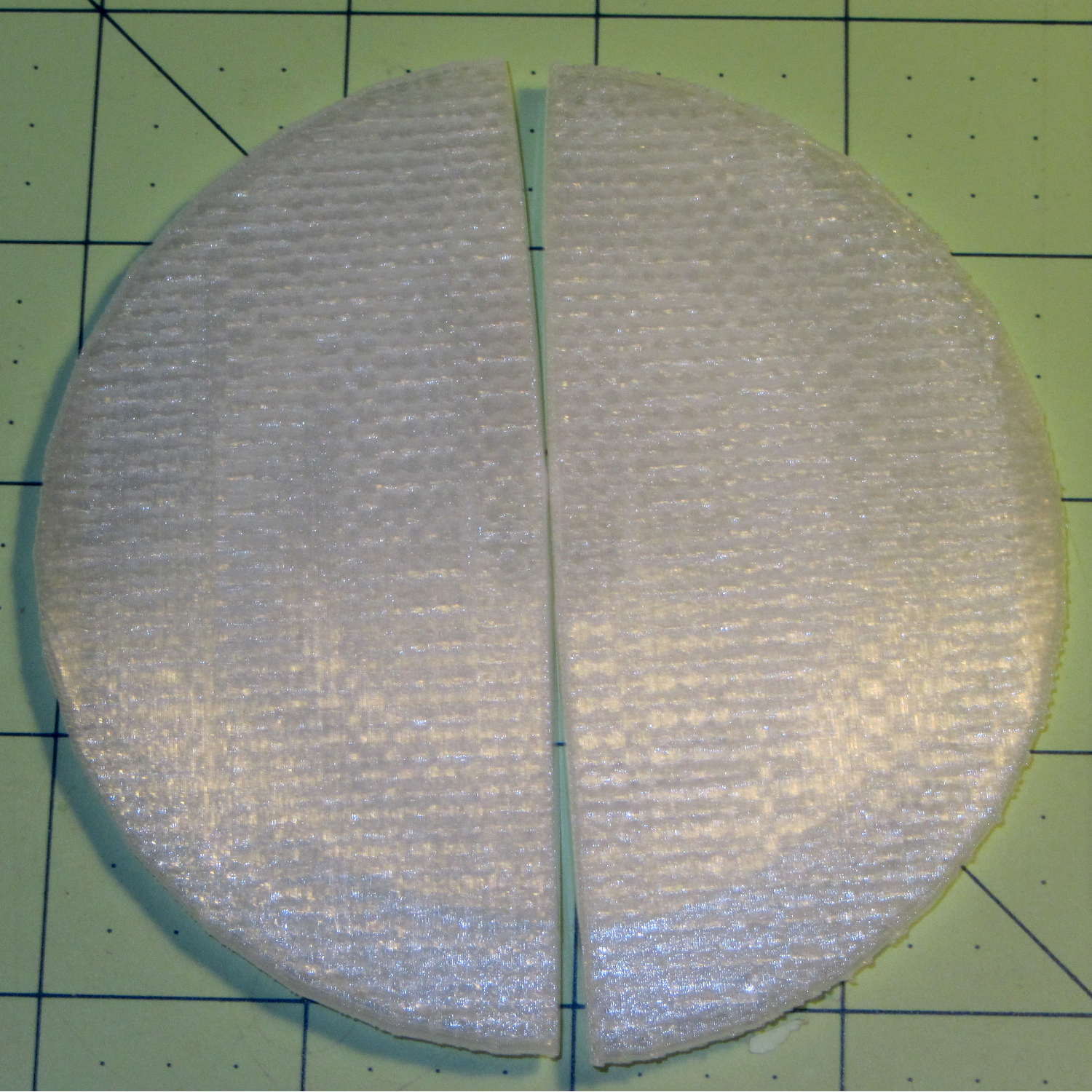
She submitted to all this nonsense with good grace and cooked up an OpenSCAD model that prints the “lens” in two halves:
Printed Lens – halves on platform
Alas, those thin flanges have too little area on the platform to resist the contraction of the plastic above, so they didn’t fit together very well at all:
Printed Lens – base distortion
We figured a large brim would solve that problem, but then it was time for her to return to the hot, fast core of college life…