|
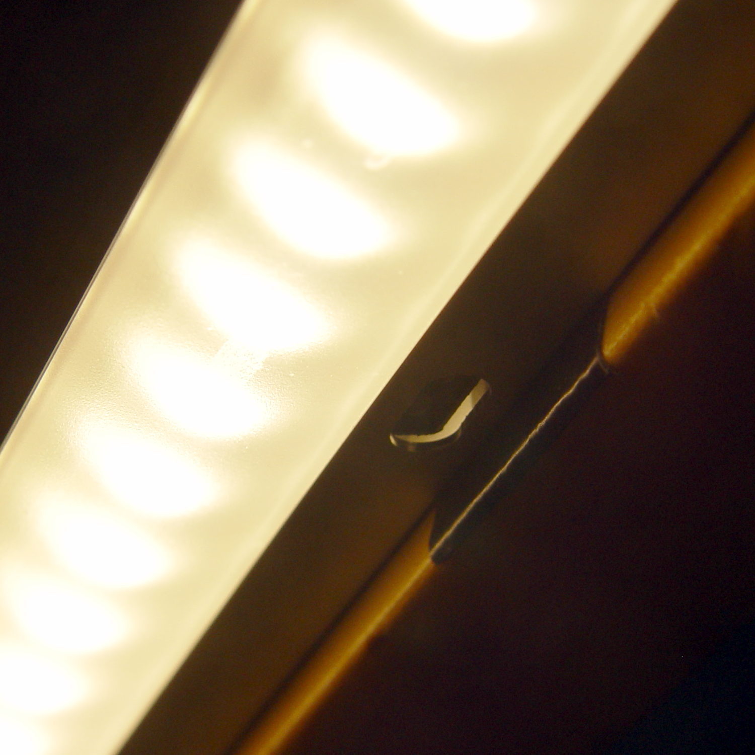
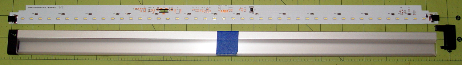
// Mounting brackets for eShine under-counter LED lights |
|
// Ed Nisley KE4ZNU December 2016 |
|
|
|
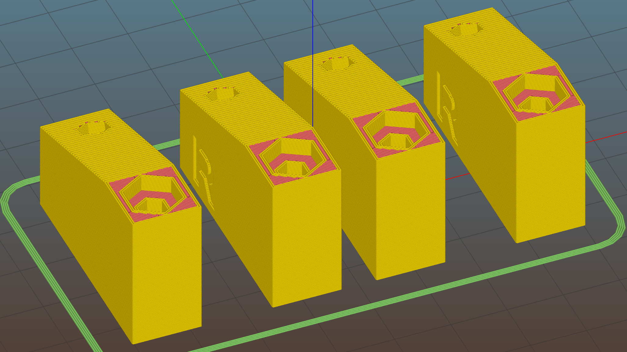
Layout = "Build"; |
|
|
|
//- Extrusion parameters must match reality! |
|
|
|
ThreadThick = 0.25; |
|
ThreadWidth = 0.40; |
|
|
|
HoleWindage = 0.2; |
|
|
|
Protrusion = 0.1; // make holes end cleanly |
|
|
|
inch = 25.4; |
|
|
|
function IntegerMultiple(Size,Unit) = Unit * ceil(Size / Unit); |
|
|
|
//———- |
|
// Dimensions |
|
|
|
MountHeight = (1 + 0*3/16) * inch; // distance from cabinet bottom |
|
|
|
THREADOD = 0; |
|
HEADOD = 1; |
|
LENGTH = 2; |
|
|
|
WoodScrew = [4.0,8.3,41]; // 8×1-5/8 Deck screw |
|
WoodScrewRecess = 3.0; |
|
WoodScrewMargin = 1.5 * WoodScrew[HEADOD]; // head OD + flat ring |
|
|
|
Insert = [3.9,4.6,5.8 + 2.0]; // 4-40 knurled brass insert |
|
|
|
JoinerLength = 19.0; // joiner between strips |
|
|
|
LEDEndBlock = [11.0,28.8,9.5]; // LED plastic end block |
|
LEDScrewOffset = [1.0,8.2,0]; // hole offset from end block center point |
|
|
|
StripAngle = atan2(LEDEndBlock[2],LEDEndBlock[1]); |
|
echo(str("Strip angle: ",StripAngle)); |
|
|
|
MountBlock = [WoodScrewMargin,(WoodScrewMargin + LEDEndBlock[1]*cos(StripAngle)),MountHeight]; |
|
|
|
//———————- |
|
// Useful routines |
|
|
|
module PolyCyl(Dia,Height,ForceSides=0) { // based on nophead's polyholes |
|
Sides = (ForceSides != 0) ? ForceSides : (ceil(Dia) + 2); |
|
FixDia = Dia / cos(180/Sides); |
|
cylinder(d=(FixDia + HoleWindage),h=Height,$fn=Sides); |
|
} |
|
|
|
//—– |
|
// LED end block with positive insert for subtraction |
|
// returned with mounting hole end of strip along X axis |
|
// ready for positioning & subtraction |
|
|
|
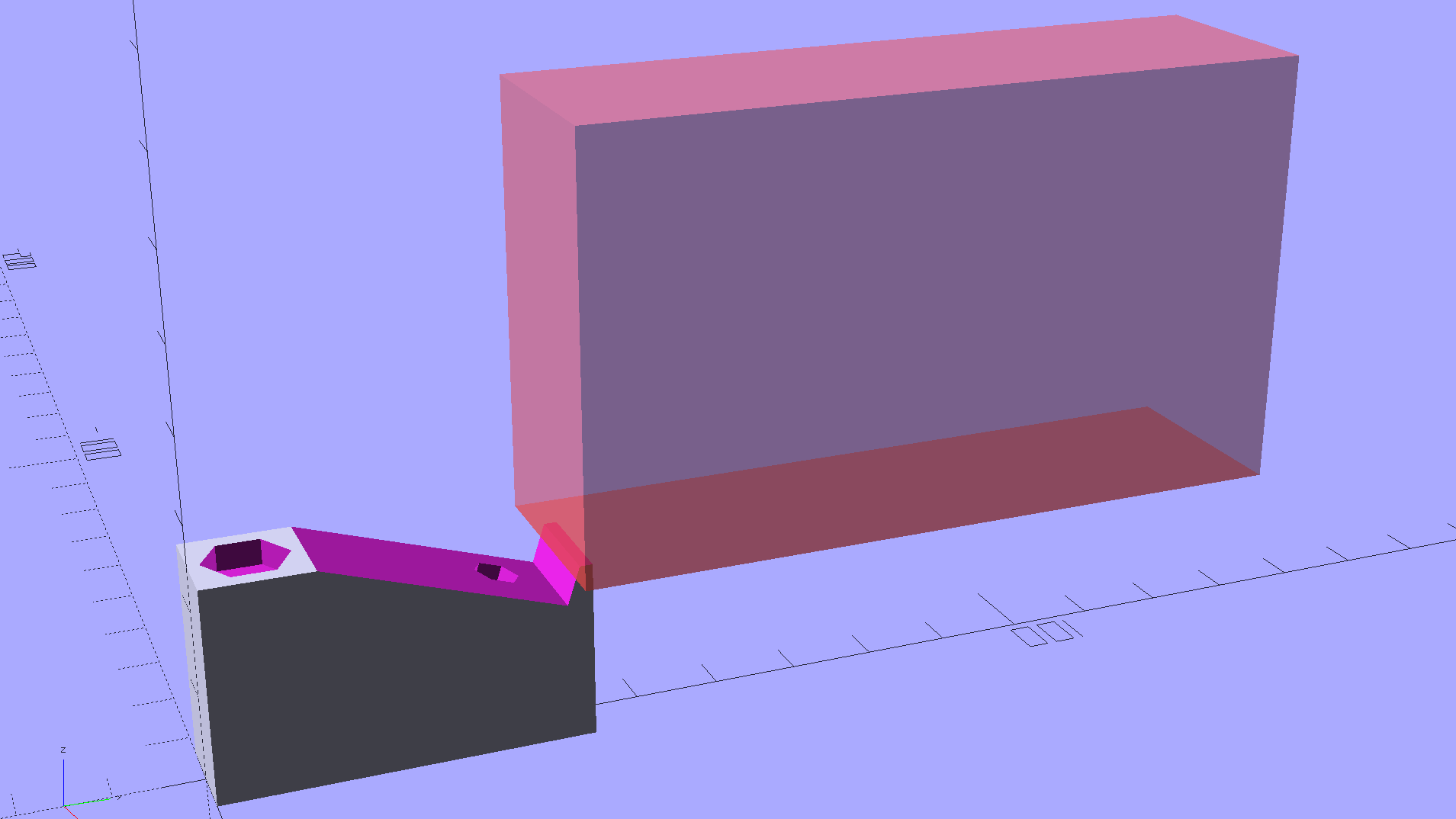
module EndBlock(Side = "L") { |
|
|
|
LSO = [((Side == "L") ? 1 : -1)*LEDScrewOffset[0],LEDScrewOffset[1],LEDScrewOffset[2]]; |
|
|
|
rotate([-StripAngle,0,0]) |
|
translate([0,LEDEndBlock[1]/2,LEDEndBlock[2]]) |
|
union() { |
|
cube(LEDEndBlock + [LEDEndBlock[0],0,LEDEndBlock[2]],center=true); |
|
translate(LSO + [0,0,-(LEDEndBlock[2] + Insert[2])]) |
|
rotate(180/6) |
|
PolyCyl(Insert[1],2*Insert[2],6); |
|
} |
|
} |
|
|
|
//—– |
|
// End mounting block with proper hole offsets |
|
|
|
module EndMount(Side = "L") { |
|
|
|
translate([0,0,MountBlock[2]/2]) |
|
difference() { |
|
translate([0,MountBlock[1]/2,0]) |
|
cube(MountBlock,center=true); |
|
|
|
translate([0,WoodScrewMargin,MountBlock[2]/2]) |
|
EndBlock(Side); |
|
|
|
translate([0,WoodScrewMargin/2,-MountBlock[2]]) |
|
rotate(180/6) |
|
PolyCyl(WoodScrew[THREADOD],2*MountBlock[2],6); |
|
|
|
translate([0,WoodScrewMargin/2,(MountBlock[2]/2 – WoodScrewRecess)]) |
|
rotate(180/6) |
|
PolyCyl(WoodScrew[HEADOD],WoodScrewRecess + Protrusion,6); |
|
|
|
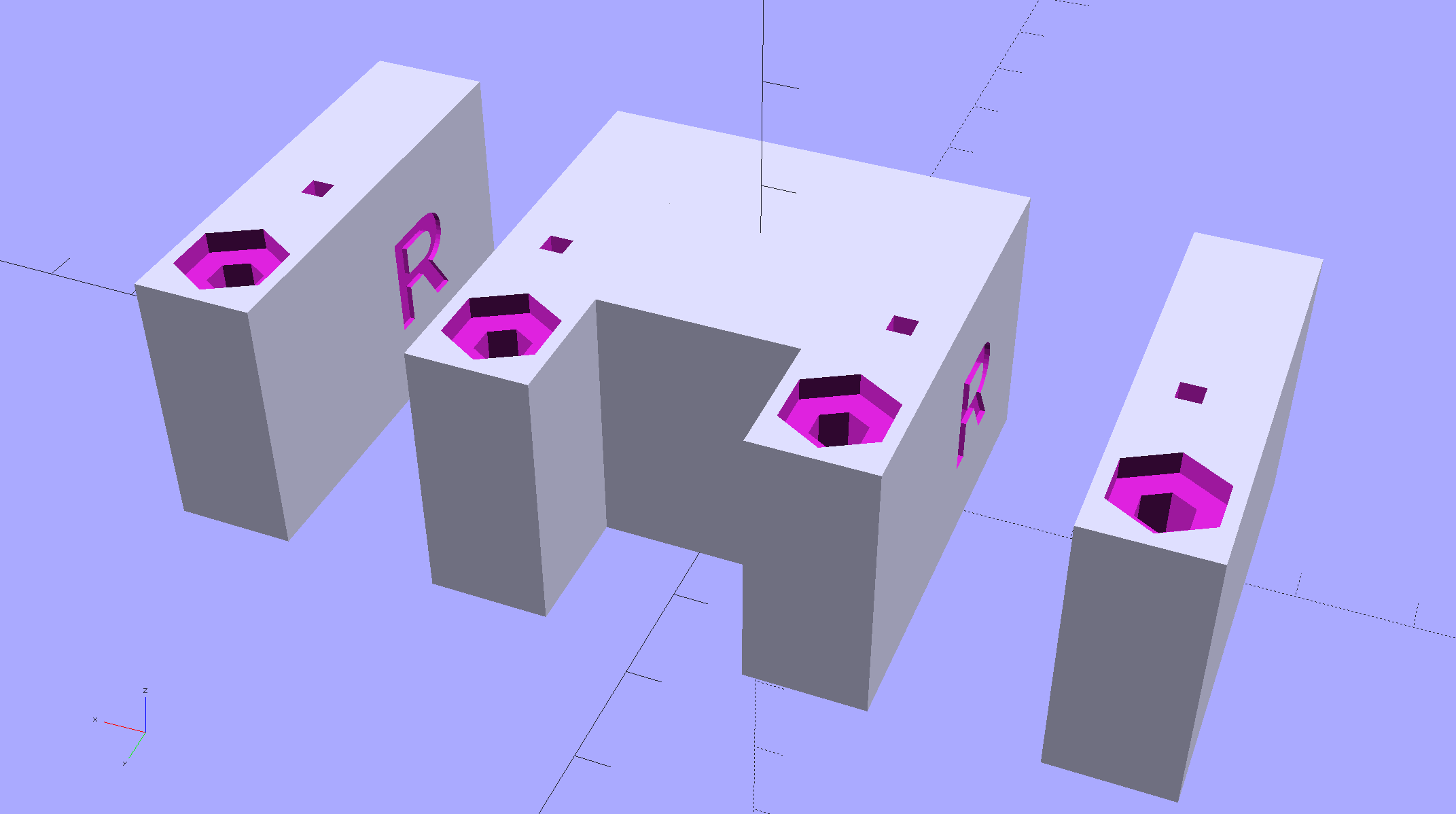
translate([((Side == "L") ? 1 : -1)*MountBlock[0]/2,3*MountBlock[1]/4,-MountBlock[2]/4]) |
|
rotate([90,0,((Side == "L") ? 1 : -1)*90]) |
|
translate([0,0,-2*ThreadThick]) |
|
linear_extrude(height=4*ThreadThick,convexity=3) |
|
text(Side,font=":style=bold",valign="center",halign="center"); |
|
} |
|
} |
|
|
|
module MidMount() { |
|
XOffset = (JoinerLength + MountBlock[0])/2; |
|
BridgeThick = 5.0; |
|
|
|
union() { |
|
translate([XOffset,0,0]) |
|
EndMount("L"); |
|
|
|
translate([0,MountBlock[1]/2,BridgeThick/2]) |
|
cube([JoinerLength,MountBlock[1],BridgeThick] + [2*Protrusion,0,0],center=true); |
|
|
|
translate([-XOffset,0,0]) |
|
EndMount("R"); |
|
} |
|
} |
|
|
|
//———- |
|
// Build them |
|
|
|
if (Layout == "EndBlock") |
|
EndBlock("L"); |
|
|
|
if (Layout == "EndMount") |
|
EndMount("R"); |
|
|
|
if (Layout == "MidMount") |
|
MidMount(); |
|
|
|
if (Layout == "BuildJoined") { |
|
translate([-(JoinerLength + 2*MountBlock[0]),0,0]) |
|
EndMount("L"); |
|
|
|
MidMount(); |
|
|
|
translate([(JoinerLength + 2*MountBlock[0]),0,0]) |
|
EndMount("R"); |
|
} |
|
|
|
if (Layout == "Build") { |
|
translate([-MountBlock[0],0,0]) |
|
EndMount("L"); |
|
|
|
translate([MountBlock[0],0,0]) |
|
EndMount("R"); |
|
} |